2007 INFINITI QX56 four wheel drive
[x] Cancel search: four wheel drivePage 614 of 3061

AV-74
< SERVICE INFORMATION >
NAVIGATION SYSTEM
Map-matching is a function that repositions the vehicle on the road
map when a new location is judged to be the most accurate. This is
done by comparing the current vehicle position, calculated by the
method described in the position detection principle, with the road
map data around the vehicle, read from the map DVD-ROM stored in
the DVD-ROM drive.
Therefore, the vehicle position may not be corrected after the vehicle
is driven over a certain distance or time in which GPS information is
hard to receive. In this case, the current-location mark on the display
must be corrected manually.
CAUTION:
The road map data is based on data stored in the map DVD-
ROM.
• In map-matching, alternative routes to reach the destination will be
shown and prioritized, after the road on which the vehicle is cur-
rently driven has been judged and the current-location mark has
been repositioned.
If there is an error in distance and/or direction, the alternative
routes will be shown in different order of priority, and the wrong
road can be avoided.
If two roads are running in parallel, they are of the same priority.
Therefore, the current-location mark may appear on either of them
alternately, depending on maneuvering of the steering wheel and
configuration of the road.
• Map-matching does not function correctly when the road on which
the vehicle is driving is new and not recorded in the map DVD-
ROM, or when the road pattern stored in the map data and the
actual road pattern are different due to repair.
When driving on a road not present in the map, the map-matching
function may find another road and position the current-location
mark on it. Then, when the correct road is detected, the current-
location mark may leap to it.
• Effective range for comparing the vehicle position and travel direc-
tion calculated by the distance and direction with the road data
read from the map DVD-ROM is limited. Therefore, when there is
an excessive gap between the current vehicle position and the
position on the map, correction by map-matching is not possible.
GPS (GLOBAL POSITIONING SYSTEM)
GPS (Global Positioning System) has been developed and con-
trolled by the US Department of Defense. The system utilizes GPS
satellite (NAVSTAR), sending out radio waves while flying on an orbit
around the earth at the height of approx. 21,000 km (13,000 miles).
The GPS receiver calculates the vehicle's position in three dimen-
sions (latitude/longitude/altitude) according to the time lag of the
radio waves received from four or more GPS satellites (three-dimen-
sional positioning). If radio waves were received only from three
GPS satellites, the GPS receiver calculates the vehicle's position in
two dimensions (latitude/longitude), utilizing the altitude data calcu-
lated previously by using radio waves from four or more GPS satel-
lites (two-dimensional positioning).
Accuracy of the GPS will deteriorate under the following conditions.
• In two-dimensional positioning, the GPS accuracy will deteriorate when the altitude of the vehicle position
changes.
• There may be an error of approximately 10 m (30 ft) in position detected by three-dimensional positioning,
which is more accurate than two-dimensional positioning. The accuracy can be even lower depending on the
arrangement of the GPS satellites utilized for the positioning.
• Position detection is not possible when the vehicle is in an area where radio waves from the GPS satellite do
not reach, such as in a tunnel, parking lot in a building, and under an elevated highway. Radio waves from
the GPS satellites may not be received when some object is located over the GPS antenna.
SEL685V
SEL686V
SKIA0613E
SEL526V
Page 2008 of 3061

GI-42
< SERVICE INFORMATION >
TOW TRUCK TOWING
TOW TRUCK TOWING
Tow Truck TowingINFOID:0000000003531499
WARNING:
• Never get under the vehicle while it is supported only by the jack. Always use safety stands to sup-
port the frame when you have to get under the vehicle.
• Place wheel chocks at both front and back of the wheels on the ground.
CAUTION:
• All applicable State or Provincial (in Canada) laws and local laws regarding the towing operation
must be obeyed.
• It is necessary to use proper towing equipment to avoid possible damage during towing operation.
Towing is in accordance with Towing Procedure Manual at dealer.
• Always attach safety chains before towing.
• When towing, make sure that the transmission, steering system and powertrain are in good order. If
any unit is damaged, dollies must be used.
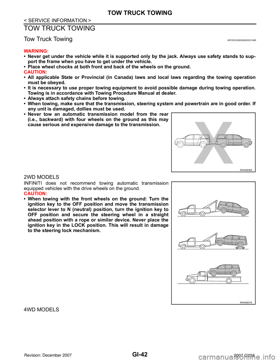
• Never tow an automatic transmission model from the rear
(i.e., backward) with four wheels on the ground as this may
cause serious and expensive damage to the transmission.
2WD MODELS
INFINITI does not recommend towing automatic transmission
equipped vehicles with the drive wheels on the ground.
CAUTION:
• When towing with the front wheels on the ground: Turn the
ignition key to the OFF position and move the transmission
selector lever to N (neutral) position, turn the ignition key to
OFF position and secure the steering wheel in a straight
ahead position with a rope or similar device. Never place the
ignition key in the LOCK position. This will result in damage
to the steering lock mechanism.
4WD MODELS
WAIA0030E
WAIA0031E
Page 2524 of 3061

RAX-6
< SERVICE INFORMATION >
WHEEL HUB
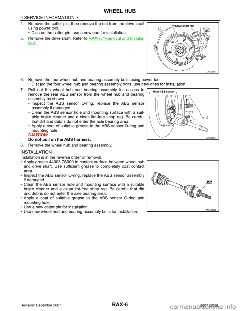
4. Remove the cotter pin, then remove the nut from the drive shaft
using power tool.
• Discard the cotter pin, use a new one for installation.
5. Remove the drive shaft. Refer to RAX-7, "
Removal and Installa-
tion".
6. Remove the four wheel hub and bearing assembly bolts using power tool.
• Discard the four wheel hub and bearing assembly bolts, use new ones for installation.
7. Pull out the wheel hub and bearing assembly for access to
remove the rear ABS sensor from the wheel hub and bearing
assembly as shown.
• Inspect the ABS sensor O-ring, replace the ABS sensor
assembly if damaged.
• Clean the ABS sensor hole and mounting surface with a suit-
able brake cleaner and a clean lint-free shop rag. Be careful
that dirt and debris do not enter the axle bearing area.
• Apply a coat of suitable grease to the ABS sensor O-ring and
mounting hole.
CAUTION:
Do not pull on the ABS harness.
8. Remove the wheel hub and bearing assembly.
INSTALLATION
Installation is in the reverse order of removal.
• Apply grease 44003 7S000 to contact surface between wheel hub
and drive shaft. Use sufficient grease to completely coat contact
area.
• Inspect the ABS sensor O-ring, replace the ABS sensor assembly
if damaged.
• Clean the ABS sensor hole and mounting surface with a suitable
brake cleaner and a clean lint-free shop rag. Be careful that dirt
and debris do not enter the axle bearing area.
• Apply a coat of suitable grease to the ABS sensor O-ring and
mounting hole.
• Use a new cotter pin for installation.
• Use new wheel hub and bearing assembly bolts for installation.
LDIA0050E
LDIA0052E
WDIA0291E