2007 INFINITI QX56 display
[x] Cancel search: displayPage 1677 of 3061
EC-594
< SERVICE INFORMATION >
DTC P2A00, P2A03 A/F SENSOR 1
2. Listen for an intake air leak after the mass air flow sensor.
OK or NG
OK >> GO TO 4.
NG >> Repair or replace.
4.CLEAR THE SELF-LEARNING DATA
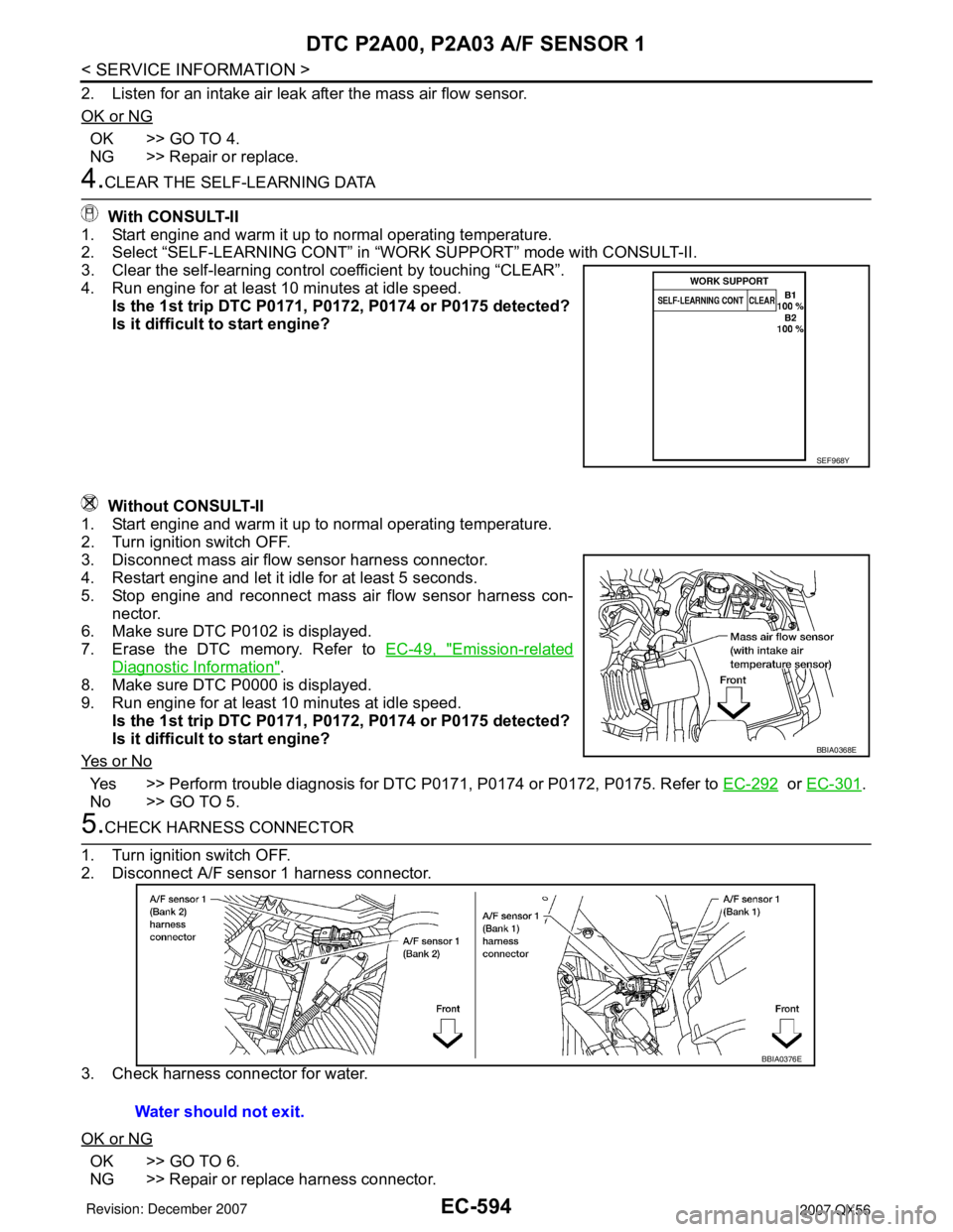
With CONSULT-II
1. Start engine and warm it up to normal operating temperature.
2. Select “SELF-LEARNING CONT” in “WORK SUPPORT” mode with CONSULT-II.
3. Clear the self-learning control coefficient by touching “CLEAR”.
4. Run engine for at least 10 minutes at idle speed.
Is the 1st trip DTC P0171, P0172, P0174 or P0175 detected?
Is it difficult to start engine?
Without CONSULT-II
1. Start engine and warm it up to normal operating temperature.
2. Turn ignition switch OFF.
3. Disconnect mass air flow sensor harness connector.
4. Restart engine and let it idle for at least 5 seconds.
5. Stop engine and reconnect mass air flow sensor harness con-
nector.
6. Make sure DTC P0102 is displayed.
7. Erase the DTC memory. Refer to EC-49, "
Emission-related
Diagnostic Information".
8. Make sure DTC P0000 is displayed.
9. Run engine for at least 10 minutes at idle speed.
Is the 1st trip DTC P0171, P0172, P0174 or P0175 detected?
Is it difficult to start engine?
Ye s o r N o
Yes >> Perform trouble diagnosis for DTC P0171, P0174 or P0172, P0175. Refer to EC-292 or EC-301.
No >> GO TO 5.
5.CHECK HARNESS CONNECTOR
1. Turn ignition switch OFF.
2. Disconnect A/F sensor 1 harness connector.
3. Check harness connector for water.
OK or NG
OK >> GO TO 6.
NG >> Repair or replace harness connector.
SEF968Y
BBIA0368E
Water should not exit.
BBIA0376E
Page 1679 of 3061
EC-596
< SERVICE INFORMATION >
DTC P2A00, P2A03 A/F SENSOR 1
OK >> GO TO 10.
NG >> GO TO 11.
10.CHECK INTERMITTENT INCIDENT
Perform EC-138
.
OK or NG
OK >> GO TO 11.
NG >> Repair or replace.
11 .REPLACE AIR FUEL RATIO (A/F) SENSOR 1
Replace malfunctioning air fuel ratio (A/F) sensor 1.
CAUTION:
• Discard any A/F sensor which has been dropped from a height of more than 0.5 m (19.7 in) onto a
hard surface such as a concrete floor; use a new one.
• Before installing new A/F sensor, clean exhaust system threads using Oxygen Sensor Thread
Cleaner tool J-43897-18 or J-43897-12 and approved anti-seize lubricant.
>> GO TO 12.
12.CONFIRM A/F ADJUSTMENT DATA
1. Turn ignition switch OFF and then ON.
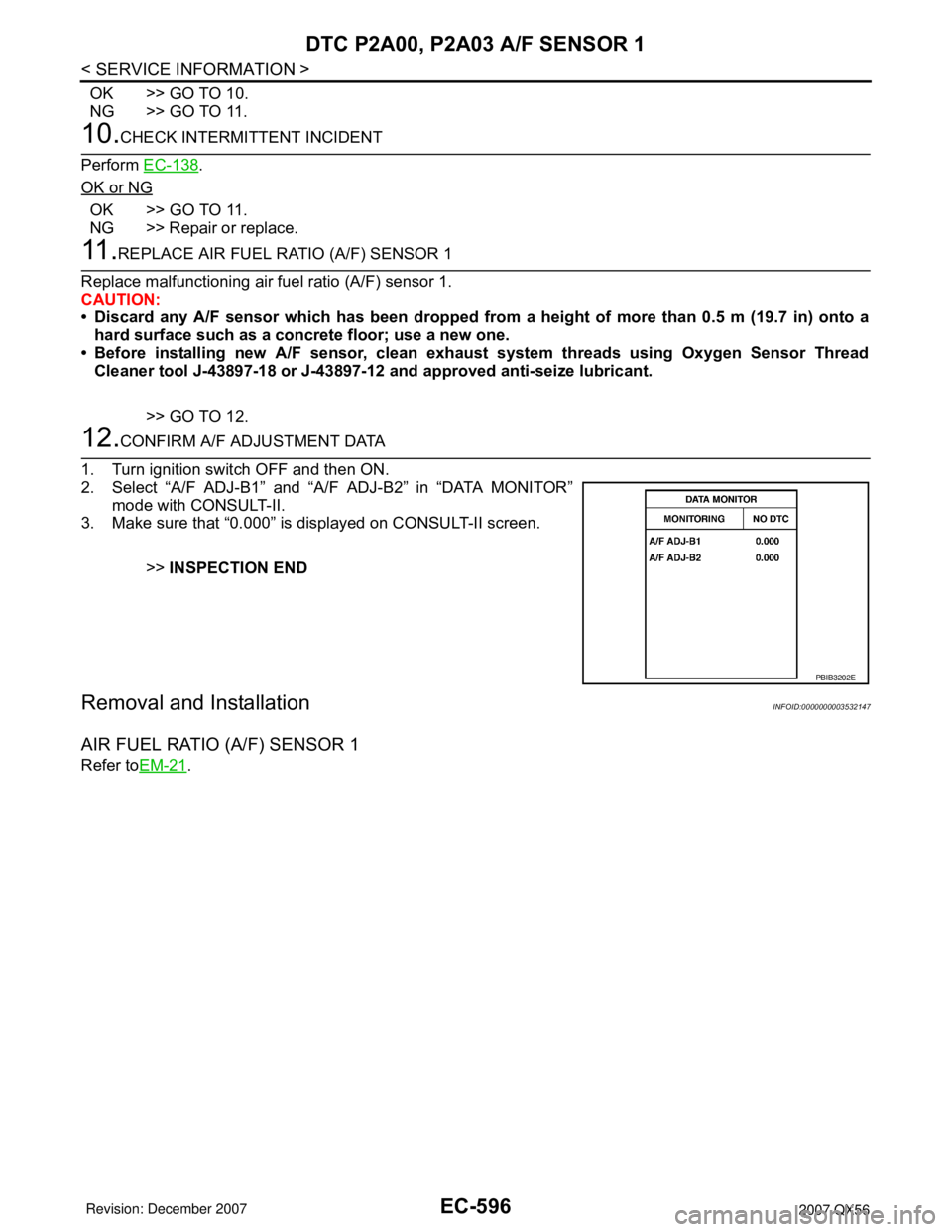
2. Select “A/F ADJ-B1” and “A/F ADJ-B2” in “DATA MONITOR”
mode with CONSULT-II.
3. Make sure that “0.000” is displayed on CONSULT-II screen.
>>INSPECTION END
Removal and InstallationINFOID:0000000003532147
AIR FUEL RATIO (A/F) SENSOR 1
Refer toEM-21.
PBIB3202E
Page 1688 of 3061
ASCD INDICATOR
EC-605
< SERVICE INFORMATION >
C
D
E
F
G
H
I
J
K
L
MA
EC
N
P O
OK or NG
OK >>INSPECTION END
NG >> GO TO 2.
2.CHECK DTC
Check that DTC U1000 or U1001 is not displayed.
OK or NG
OK >> GO TO 3.
NG >> Perform trouble diagnosis for DTC U1000, U1001. Refer to EC-145
.
3.CHECK COMBINATION METER FUNCTION
Refer to DI-5
.
OK or NG
OK >> GO TO 4.
NG >> Go to DI-5
.
4.CHECK INTERMITTENT INCIDENT
Refer to EC-138
.
>>INSPECTION END
ASCD INDICATOR CONDITION SPECIFICATION
CRUISE LAMP • Ignition switch: ON• MAIN switch: Pressed at the 1st
time → at the 2nd timeON → OFF
SET LAMP• MAIN switch: ON
• When vehicle speed is between
40 km/h (25 MPH) and 144 km/h
(89 MPH)•ASCD: Operating ON
• ASCD: Not operating OFF
Page 1765 of 3061
EI-36
< SERVICE INFORMATION >
FLOOR TRIM
FLOOR TRIM
Removal and InstallationINFOID:0000000003533137
REMOVAL
1. Remove front seats. Refer to SE-83 .
• Remove subwoofer. Refer to AV-46, "
Removal and Installation" .
• Remove navigation display control unit. Refer to AV-145, "
Removal and Installation" .
2. Remove second row seats. Refer to SE-89, "
Removal and Installation" and SE-89, "Removal and Instal-
lation" , if equipped.
3. Remove third row rear seats. Refer to SE-95
.
4. Remove lower seat belt anchors. Refer to SB-3
.
5. Remove lower body side trim. Refer to EI-34
.
6. Remove luggage lower side finishers (left / right). Refer to EI-39
.
7. Remove kicking plates. Refer to EI-34
.
8. Remove center console. Refer to IP-10
.
9. Remove rear console, if equipped. Refer to IP-14, "
Disassembly and Assembly" .
10. Remove rear lower finisher. Refer to EI-39
.
11. Remove carpet.
12. Remove floor mat hook from front carpet.
INSTALLATION
Installation is in the reverse order of removal.
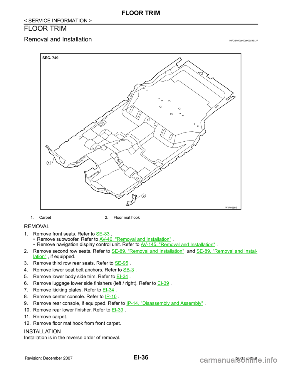
1. Carpet 2. Floor mat hook
WIIA0968E
Page 1767 of 3061
EI-38
< SERVICE INFORMATION >
HEADLINING
CAUTION:
Disconnect both terminals from battery in advance.
REMOVAL
1. Disconnect the battery negative and positive cables, then wait at least 3 minutes.
2. Remove body side trim. Refer to EI-34
.
3. Remove luggage floor trim. Refer to EI-39
.
4. Remove sunvisor assemblies.
5. Remove sunvisor clips.
6. Remove sunroof welt (if equipped).
7. Remove front roof console.
• Disconnect harnesses.
8. Remove rear roof console.
• Disconnect harnesses.
9. Remove assist grips.
10. Remove lamp assembly and rear roof finisher.
• Disconnect harness.
11. Remove headlining.
• Remove clips from rear of headlining.
• Disconnect harnesses.
12. Remove rear air control.
• Disconnect harness.
13. Remove rear audio control assembly.
• Disconnect harness.
14. Remove lamp assemblies.
• Disconnect harnesses.
15. Remove air vents.
16. Remove the front roof console bracket.
17. Remove rear roof console front bracket.
18. Remove assist grip brackets from roof.
INSTALLATION
Installation is in the reverse order of removal.
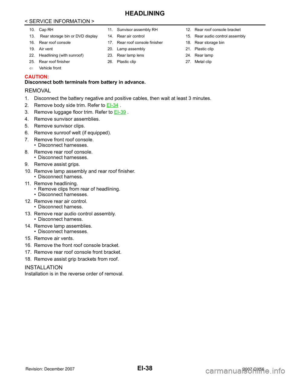
10. Cap RH 11. Sunvisor assembly RH 12. Rear roof console bracket
13. Rear storage bin or DVD display 14. Rear air control 15. Rear audio control assembly
16. Rear roof console 17. Rear roof console finisher 18. Rear storage bin
19. Air vent 20. Lamp assembly 21. Plastic clip
22. Headlining (with sunroof) 23. Rear lamp lens 24. Rear lamp
25. Rear roof finisher 26. Plastic clip 27. Metal clip
⇐Vehicle front
Page 1953 of 3061
ON-VEHICLE SERVICE
FSU-7
< SERVICE INFORMATION >
C
D
F
G
H
I
J
K
L
MA
B
FSU
N
O
P
• Check with the manufacturer of your specific alignment machine for their recommended Service/Cali-
bration Schedule.
THE ALIGNMENT PROCESS
IMPORTANT: Use only the alignment specifications listed in this Service Manual. Refer to FSU-19, "Wheel
Alignment (Unladen*1) *6".
1. When displaying the alignment settings, many alignment machines use “indicators”: (Green/red, plus or
minus, Go/No Go). Do NOT use these indicators.
• The alignment specifications programmed into your alignment machine that operate these indicators
may not be correct.
• This may result in an ERROR.
2. Some newer alignment machines are equipped with an optional “Rolling Compensation” method to “com-
pensate” the sensors (alignment targets or head units). Do NOT use this “Rolling Compensation”
method.
• Use the “Jacking Compensation” method. After installing the alignment targets or head units, raise the
vehicle and rotate the wheels 1/2 turn both ways.
• See Instructions in the alignment machine you are using for more information.
CAMBER AND CASTER
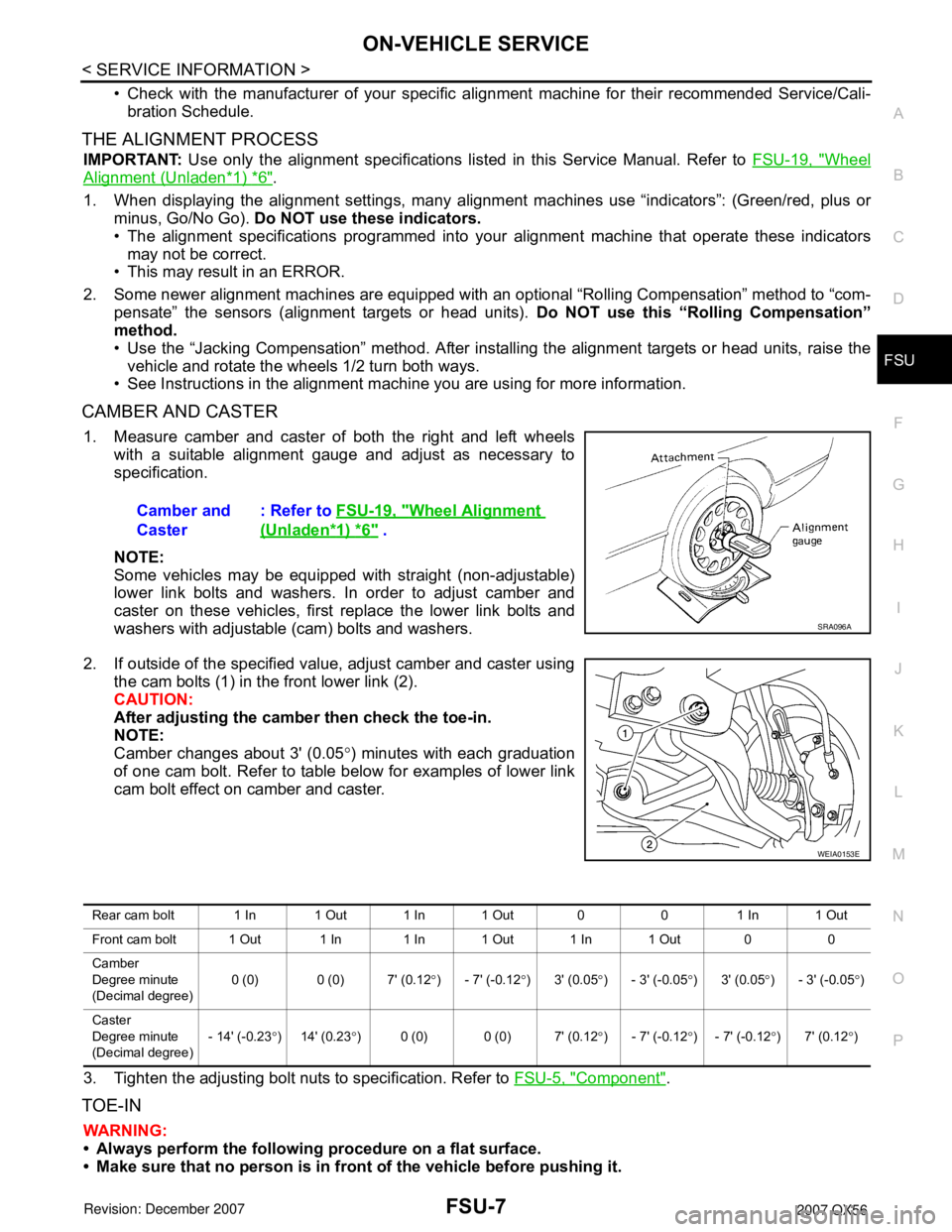
1. Measure camber and caster of both the right and left wheels
with a suitable alignment gauge and adjust as necessary to
specification.
NOTE:
Some vehicles may be equipped with straight (non-adjustable)
lower link bolts and washers. In order to adjust camber and
caster on these vehicles, first replace the lower link bolts and
washers with adjustable (cam) bolts and washers.
2. If outside of the specified value, adjust camber and caster using
the cam bolts (1) in the front lower link (2).
CAUTION:
After adjusting the camber then check the toe-in.
NOTE:
Camber changes about 3' (0.05°) minutes with each graduation
of one cam bolt. Refer to table below for examples of lower link
cam bolt effect on camber and caster.
3. Tighten the adjusting bolt nuts to specification. Refer to FSU-5, "
Component".
TOE-IN
WARNING:
• Always perform the following procedure on a flat surface.
• Make sure that no person is in front of the vehicle before pushing it.Camber and
Caster: Refer to FSU-19, "
Wheel Alignment
(Unladen*1) *6" .
SRA096A
WEIA0153E
Rear cam bolt 1 In 1 Out 1 In 1 Out 0 0 1 In 1 Out
Front cam bolt 1 Out 1 In 1 In 1 Out 1 In 1 Out 0 0
Camber
Degree minute
(Decimal degree)0 (0) 0 (0) 7' (0.12°) - 7' (-0.12°)3' (0.05°) - 3' (-0.05°)3' (0.05°) - 3' (-0.05°)
Caster
Degree minute
(Decimal degree)- 14' (-0.23°)14' (0.23°) 0 (0) 0 (0) 7' (0.12°) - 7' (-0.12°) - 7' (-0.12°)7' (0.12°)
Page 2001 of 3061
CONSULT-II CHECKING SYSTEM
GI-35
< SERVICE INFORMATION >
C
D
E
F
G
H
I
J
K
L
MB
GI
N
O
PCONSULT-II CHECKING SYSTEM
DescriptionINFOID:0000000003531490
• CONSULT-II is a hand-held type tester. When it is connected with a diagnostic connector equipped on the
vehicle side, it will communicate with the control unit equipped in the vehicle and then enable various kinds
of diagnostic tests.
• Refer to “CONSULT-II Software Operation Manual” for more information.
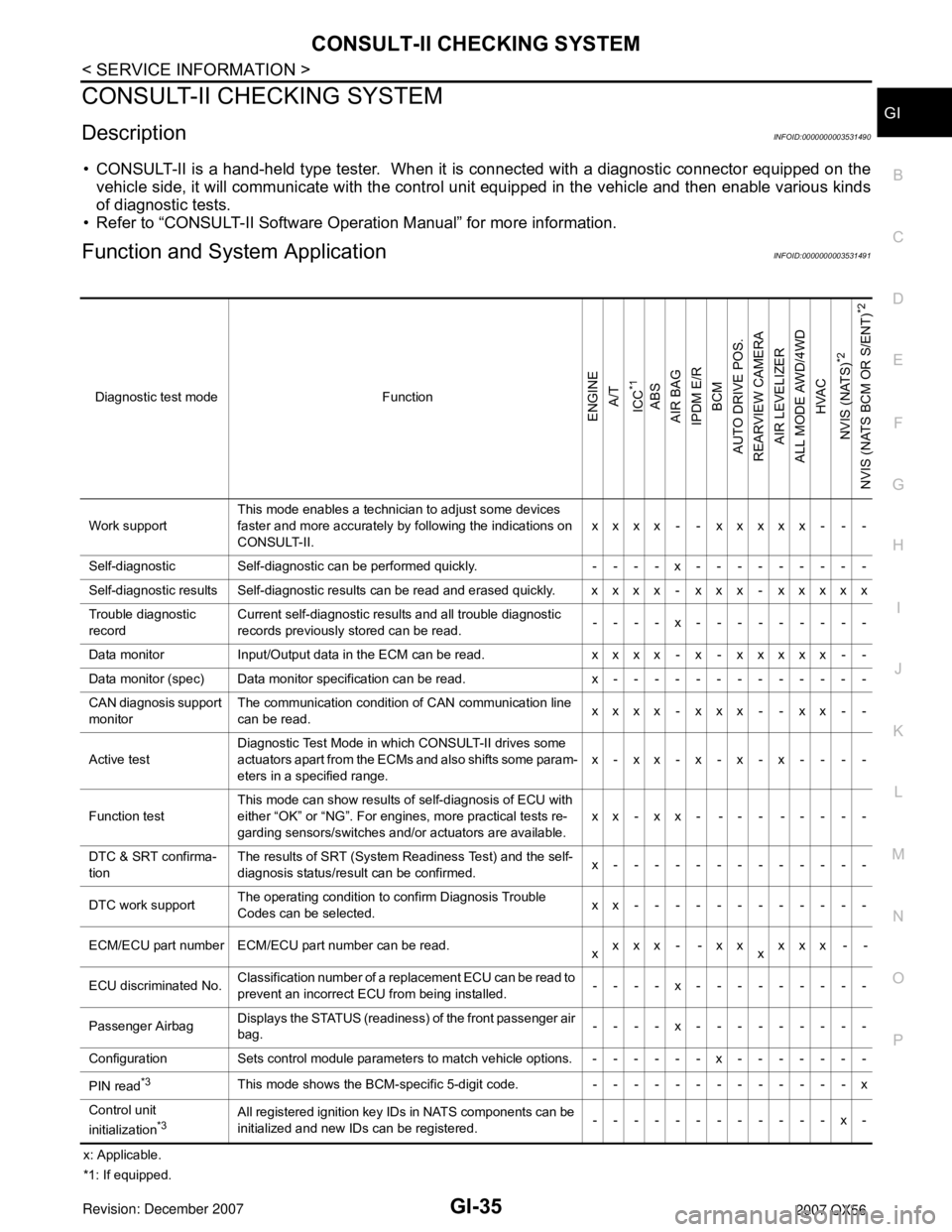
Function and System ApplicationINFOID:0000000003531491
x: Applicable.
*1: If equipped.Diagnostic test mode Function
ENGINE
A/T
ICC
*1
ABS
AIR BAG
IPDM E/R
BCM
AUTO DRIVE POS.
REARVIEW CAMERA
AIR LEVELIZER
ALL MODE AWD/4WD
HVAC
NVIS (NATS)
*2
NVIS (NATS BCM OR S/ENT)
*2
Work supportThis mode enables a technician to adjust some devices
faster and more accurately by following the indications on
CONSULT-II.xxxx - - xxxxx - - -
Self-diagnostic Self-diagnostic can be performed quickly. ----x---------
Self-diagnostic results Self-diagnostic results can be read and erased quickly. xxxx - xxx - xxxxx
Trouble diagnostic
recordCurrent self-diagnostic results and all trouble diagnostic
records previously stored can be read.--- - x---------
Data monitor Input/Output data in the ECM can be read. xxxx - x - xxxxx - -
Data monitor (spec) Data monitor specification can be read. x-------------
CAN diagnosis support
monitorThe communication condition of CAN communication line
can be read.xxxx - xxx - - xx - -
Active testDiagnostic Test Mode in which CONSULT-II drives some
actuators apart from the ECMs and also shifts some param-
eters in a specified range.x-xx-x-x-x----
Function testThis mode can show results of self-diagnosis of ECU with
either “OK” or “NG”. For engines, more practical tests re-
garding sensors/switches and/or actuators are available.xx-xx- --- -----
DTC & SRT confirma-
tionThe results of SRT (System Readiness Test) and the self-
diagnosis status/result can be confirmed.x-------------
DTC work supportThe operating condition to confirm Diagnosis Trouble
Codes can be selected.xx------------
ECM/ECU part number ECM/ECU part number can be read.
xxxx - -xx
xxxx - -
ECU discriminated No.Classification number of a replacement ECU can be read to
prevent an incorrect ECU from being installed.----x---------
Passenger Airbag Displays the STATUS (readiness) of the front passenger air
bag.----x---------
Configuration Sets control module parameters to match vehicle options. ------x-------
PIN read
*3This mode shows the BCM-specific 5-digit code. -------------x
Control unit
initialization
*3All registered ignition key IDs in NATS components can be
initialized and new IDs can be registered.------------x-
Page 2050 of 3061
POWER WINDOW SYSTEM
GW-31
< SERVICE INFORMATION >
C
D
E
F
G
H
J
K
L
MA
B
GW
N
O
P
Terminal and Reference Value for BCMINFOID:0000000003533033
Refer to BCS-11, "Terminal and Reference Value for BCM".
Work FlowINFOID:0000000003533034
1. Check the symptom and customer's requests.
2. Understand the outline of system. Refer to GW-15, "
System Description".
3. According to the trouble diagnosis chart, repair or replace the cause of the malfunction.
Refer to GW-32, "
Trouble Diagnosis Symptom Chart".
4. Does power window system operate normally? Yes, GO TO 5, If No, GO TO 3.
5. Inspection End.
CONSULT-II Function (BCM)INFOID:0000000003533035
CONSULT-II can display each diagnostic item using the diagnostic test modes shown following.
CONSULT-II START PROCEDURE
Refer to GI-36, "CONSULT-II Start Procedure".
ACTIVE TEST
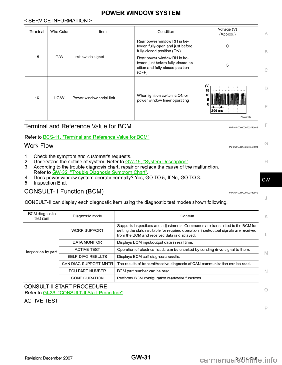
15 G/W Limit switch signalRear power window RH is be-
tween fully-open and just before
fully-closed position (ON)0
Rear power window RH is be-
tween just before fully-closed po-
sition and fully-closed position
(OFF)5
16 LG/W Power window serial linkWhen ignition switch is ON or
power window timer operating Terminal Wire Color Item ConditionVoltage (V)
(Approx.)
PIIA2344J
BCM diagnostic
test itemDiagnostic mode Content
Inspection by partWORK SUPPORTSupports inspections and adjustments. Commands are transmitted to the BCM for
setting the status suitable for required operation, input/output signals are received
from the BCM and received data is displayed.
DATA MONITOR Displays BCM input/output data in real time.
ACTIVE TEST Operation of electrical loads can be checked by sending drive signal to them.
SELF-DIAG RESULTS Displays BCM self-diagnosis results.
CAN DIAG SUPPORT MNTR The results of transmit/receive diagnosis of CAN communication can be read.
ECU PART NUMBER BCM part number can be read.
CONFIGURATION Performs BCM configuration read/write functions.