2007 INFINITI QX56 fuse box
[x] Cancel search: fuse boxPage 2127 of 3061
INSTRUMENT PANEL ASSEMBLY
IP-15
< SERVICE INFORMATION >
C
D
E
F
G
H
J
K
L
MA
B
IP
N
O
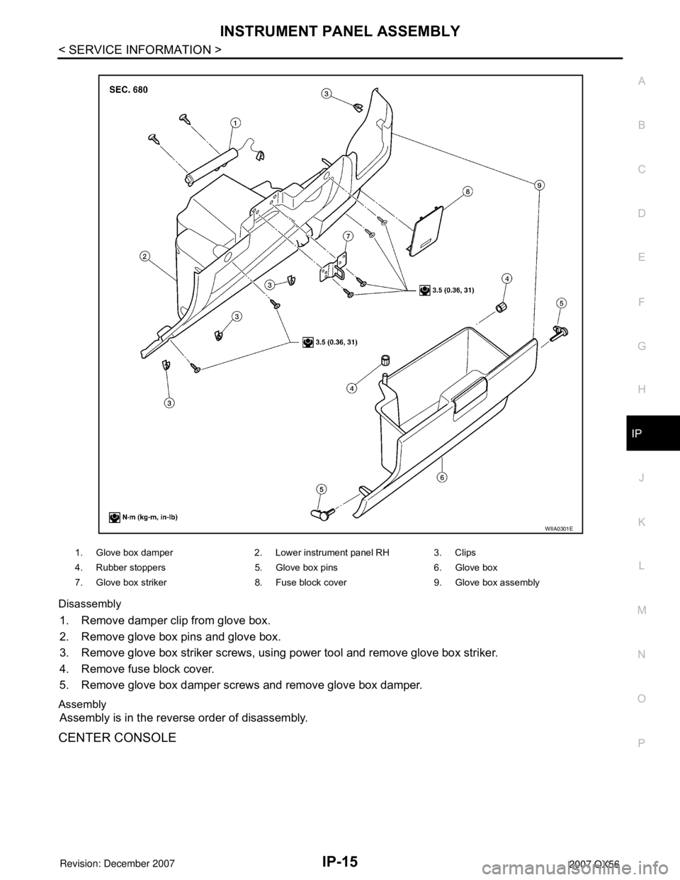
P Disassembly
1. Remove damper clip from glove box.
2. Remove glove box pins and glove box.
3. Remove glove box striker screws, using power tool and remove glove box striker.
4. Remove fuse block cover.
5. Remove glove box damper screws and remove glove box damper.
Assembly
Assembly is in the reverse order of disassembly.
CENTER CONSOLE
1. Glove box damper 2. Lower instrument panel RH 3. Clips
4. Rubber stoppers 5. Glove box pins 6. Glove box
7. Glove box striker 8. Fuse block cover 9. Glove box assembly
WIIA0301E
Page 2212 of 3061
HEADLAMP (FOR USA)
LT-5
< SERVICE INFORMATION >
C
D
E
F
G
H
I
J
L
MA
B
LT
N
O
P
HEADLAMP (FOR USA)
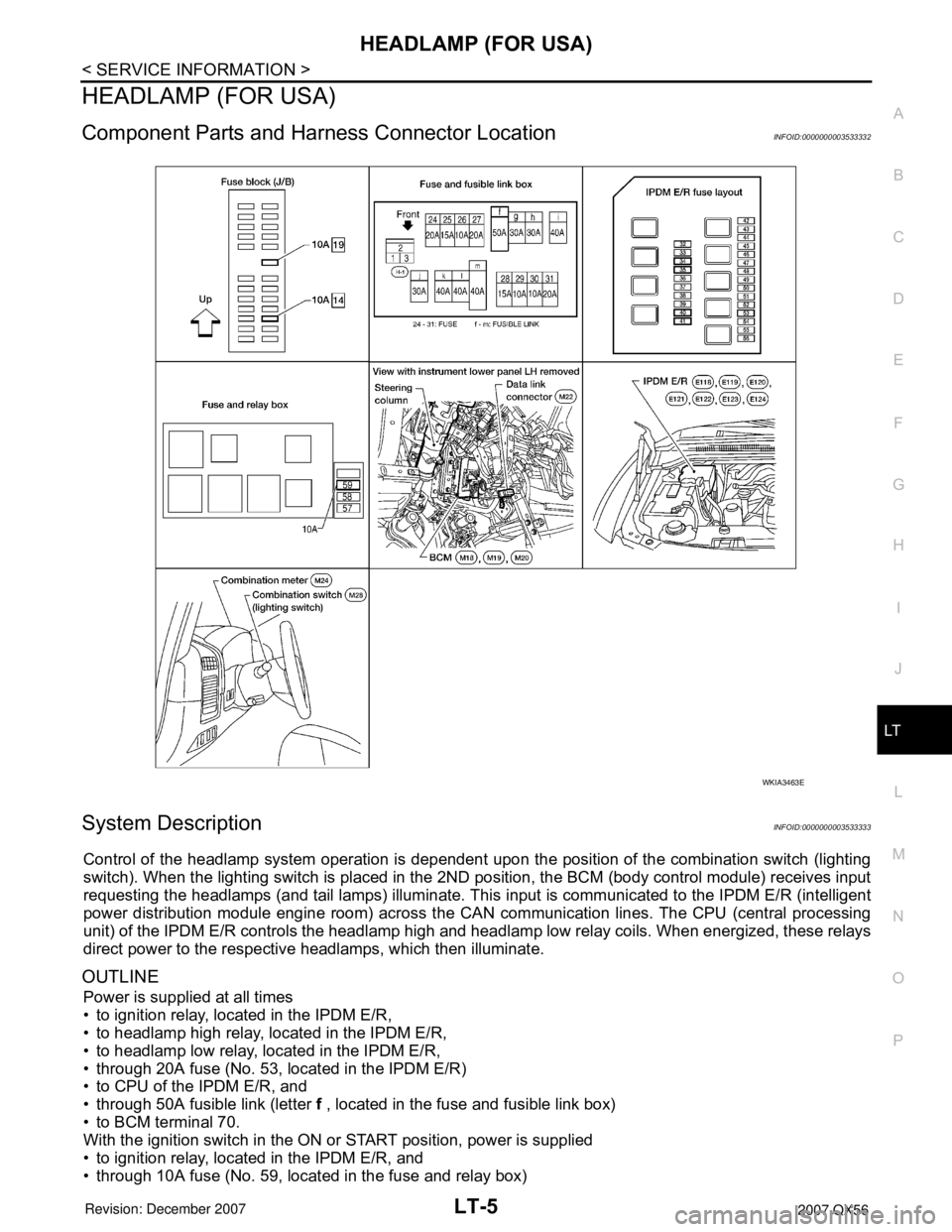
Component Parts and Harness Connector LocationINFOID:0000000003533332
System DescriptionINFOID:0000000003533333
Control of the headlamp system operation is dependent upon the position of the combination switch (lighting
switch). When the lighting switch is placed in the 2ND position, the BCM (body control module) receives input
requesting the headlamps (and tail lamps) illuminate. This input is communicated to the IPDM E/R (intelligent
power distribution module engine room) across the CAN communication lines. The CPU (central processing
unit) of the IPDM E/R controls the headlamp high and headlamp low relay coils. When energized, these relays
direct power to the respective headlamps, which then illuminate.
OUTLINE
Power is supplied at all times
• to ignition relay, located in the IPDM E/R,
• to headlamp high relay, located in the IPDM E/R,
• to headlamp low relay, located in the IPDM E/R,
• through 20A fuse (No. 53, located in the IPDM E/R)
• to CPU of the IPDM E/R, and
• through 50A fusible link (letter f , located in the fuse and fusible link box)
• to BCM terminal 70.
With the ignition switch in the ON or START position, power is supplied
• to ignition relay, located in the IPDM E/R, and
• through 10A fuse (No. 59, located in the fuse and relay box)
WKIA3463E
Page 2232 of 3061
HEADLAMP (FOR CANADA) - DAYTIME LIGHT SYSTEM -
LT-25
< SERVICE INFORMATION >
C
D
E
F
G
H
I
J
L
MA
B
LT
N
O
P
lamps turn off when lighting switch is in the 2ND position or AUTO position (Headlamp is "ON") and when light-
ing switch is in the PASSING position. (Daytime light lamps are not turned off only by parking brake itself.)
A parking brake signal and engine run or stop signal are sent to BCM (body control module) by CAN commu-
nication line.
OUTLINE
Power is supplied at all times
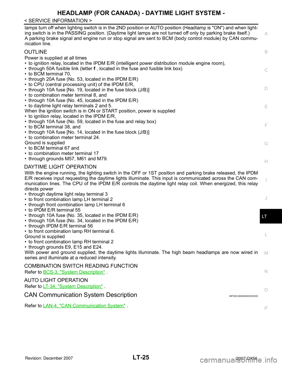
• to ignition relay, located in the IPDM E/R (intelligent power distribution module engine room),
• through 50A fusible link (letter f , located in the fuse and fusible link box)
• to BCM terminal 70,
• through 20A fuse (No. 53, located in the IPDM E/R)
• to CPU (central processing unit) of the IPDM E/R,
• through 10A fuse [No. 19, located in the fuse block (J/B)]
• to combination meter terminal 8, and
• through 10A fuse (No. 45, located in the IPDM E/R)
• to daytime light relay terminals 2 and 5.
When the ignition switch is in ON or START position, power is supplied
• to ignition relay, located in the IPDM E/R,
• through 10A fuse (No. 59, located in the fuse and relay box)
• to BCM terminal 38, and
• through 10A fuse [No. 14, located in the fuse block (J/B)]
• to combination meter terminal 24.
Ground is supplied
• to BCM terminal 67 and
• to combination meter terminal 17
• through grounds M57, M61 and M79.
DAYTIME LIGHT OPERATION
With the engine running, the lighting switch in the OFF or 1ST position and parking brake released, the IPDM
E/R receives input requesting the daytime lights illuminate. This input is communicated across the CAN com-
munication lines. The CPU of the IPDM E/R controls the daytime light relay coil. When energized, this relay
directs power
• through daytime light relay terminal 3
• to front combination lamp LH terminal 2
• through front combination lamp LH terminal 6
• to IPDM E/R terminal 55
• through 10A fuse (No. 35, located in the IPDM E/R)
• through 10A fuse (No. 34, located in the IPDM E/R)
• through IPDM E/R terminal 56
• to front combination lamp RH terminal 6.
Ground is supplied
• to front combination lamp RH terminal 2
• through grounds E9, E15 and E24.
With power and ground supplied, the daytime lights illuminate. The high beam headlamps are now wired in
series and illuminate at a reduced intensity.
COMBINATION SWITCH READING FUNCTION
Refer to BCS-3, "System Description" .
AUTO LIGHT OPERATION
Refer to LT-34, "System Description" .
CAN Communication System DescriptionINFOID:0000000003533355
Refer to LAN-4, "CAN Communication System" .
Page 2252 of 3061

HEADLAMP AIMING CONTROL
LT-45
< SERVICE INFORMATION >
C
D
E
F
G
H
I
J
L
MA
B
LT
N
O
P
HEADLAMP AIMING CONTROL
System DescriptionINFOID:0000000003533384
The headlamp aiming system is controlled by the headlamp aiming switch.
Power is supplied at all times
• to ignition relay, located in the IPDM E/R (intelligent power distribution module engine room), and
• through 50A fusible link (letter f , located in the fuse and fusible link box)
• to BCM (body control module) terminal 70, and
• to headlamp low relay, located in the IPDM E/R (intelligent power distribution module engine room), and
• through 20A fuse (No. 53, located in the IPDM E/R)
• to CPU (central processing unit) of the IPDM E/R.
With the ignition switch in the ON or START position, power is supplied
• to ignition relay, located in the IPDM E/R, and
• through 10A fuse (No. 59, located in the fuse and relay box)
• to BCM terminal 38.
When the ignition switch is in the ACC or ON position, power is supplied
• through 10A fuse [No. 4, located in the fuse block (J/B)]
• to BCM terminal 11.
When the lighting switch is in the 2ND position or AUTO position (auto lights ON), the headlamp low relay
(located in the IPDM E/R) is energized. When energized, power is supplied
• through 15A fuse (No. 41, located in the IPDM E/R)
• through IPDM E/R terminal 26
• to front combination lamp LH and RH (headlamp aiming motor) terminal 8.
Ground is supplied
• to front combination lamp LH and RH (headlamp aiming motor) terminal 4
• through grounds E9, E15 and E24, and
• to front combination lamp LH and RH (headlamp aiming motor) terminal 7
• through headlamp aiming switch terminal 1
• through headlamp aiming switch terminal 2
• through grounds M57, M61 and M79.
With power and ground supplied, headlamp aiming motors operate according to the aiming switch position.
Page 2256 of 3061
FRONT FOG LAMP
LT-49
< SERVICE INFORMATION >
C
D
E
F
G
H
I
J
L
MA
B
LT
N
O
P
FRONT FOG LAMP
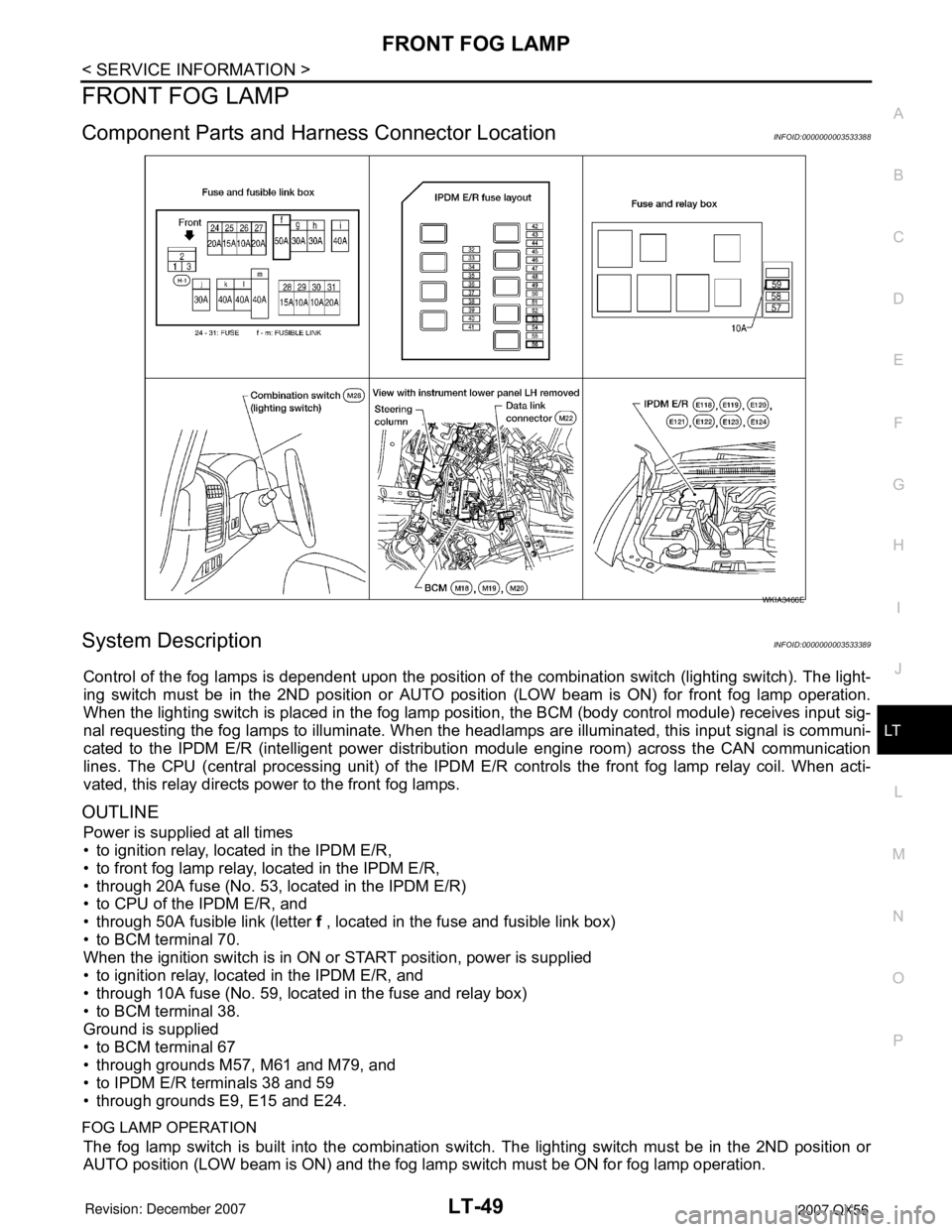
Component Parts and Harness Connector LocationINFOID:0000000003533388
System DescriptionINFOID:0000000003533389
Control of the fog lamps is dependent upon the position of the combination switch (lighting switch). The light-
ing switch must be in the 2ND position or AUTO position (LOW beam is ON) for front fog lamp operation.
When the lighting switch is placed in the fog lamp position, the BCM (body control module) receives input sig-
nal requesting the fog lamps to illuminate. When the headlamps are illuminated, this input signal is communi-
cated to the IPDM E/R (intelligent power distribution module engine room) across the CAN communication
lines. The CPU (central processing unit) of the IPDM E/R controls the front fog lamp relay coil. When acti-
vated, this relay directs power to the front fog lamps.
OUTLINE
Power is supplied at all times
• to ignition relay, located in the IPDM E/R,
• to front fog lamp relay, located in the IPDM E/R,
• through 20A fuse (No. 53, located in the IPDM E/R)
• to CPU of the IPDM E/R, and
• through 50A fusible link (letter f , located in the fuse and fusible link box)
• to BCM terminal 70.
When the ignition switch is in ON or START position, power is supplied
• to ignition relay, located in the IPDM E/R, and
• through 10A fuse (No. 59, located in the fuse and relay box)
• to BCM terminal 38.
Ground is supplied
• to BCM terminal 67
• through grounds M57, M61 and M79, and
• to IPDM E/R terminals 38 and 59
• through grounds E9, E15 and E24.
FOG LAMP OPERATION
The fog lamp switch is built into the combination switch. The lighting switch must be in the 2ND position or
AUTO position (LOW beam is ON) and the fog lamp switch must be ON for fog lamp operation.
WKIA3466E
Page 2264 of 3061
TURN SIGNAL AND HAZARD WARNING LAMPS
LT-57
< SERVICE INFORMATION >
C
D
E
F
G
H
I
J
L
MA
B
LT
N
O
P
TURN SIGNAL AND HAZARD WARNING LAMPS
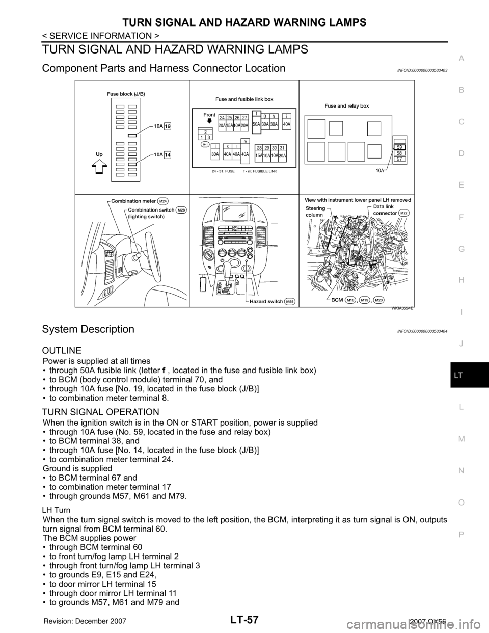
Component Parts and Harness Connector LocationINFOID:0000000003533403
System DescriptionINFOID:0000000003533404
OUTLINE
Power is supplied at all times
• through 50A fusible link (letter f , located in the fuse and fusible link box)
• to BCM (body control module) terminal 70, and
• through 10A fuse [No. 19, located in the fuse block (J/B)]
• to combination meter terminal 8.
TURN SIGNAL OPERATION
When the ignition switch is in the ON or START position, power is supplied
• through 10A fuse (No. 59, located in the fuse and relay box)
• to BCM terminal 38, and
• through 10A fuse [No. 14, located in the fuse block (J/B)]
• to combination meter terminal 24.
Ground is supplied
• to BCM terminal 67 and
• to combination meter terminal 17
• through grounds M57, M61 and M79.
LH Turn
When the turn signal switch is moved to the left position, the BCM, interpreting it as turn signal is ON, outputs
turn signal from BCM terminal 60.
The BCM supplies power
• through BCM terminal 60
• to front turn/fog lamp LH terminal 2
• through front turn/fog lamp LH terminal 3
• to grounds E9, E15 and E24,
• to door mirror LH terminal 15
• through door mirror LH terminal 11
• to grounds M57, M61 and M79 and
WKIA3554E
Page 2265 of 3061

LT-58
< SERVICE INFORMATION >
TURN SIGNAL AND HAZARD WARNING LAMPS
• to rear combination lamp LH terminal 4
• through rear combination signal lamp LH terminal 6
• to grounds B7 and B19.
BCM sends signal to combination meter through CAN communication lines, and turns on turn signal indicator
lamp within combination meter.
RH Turn
When the turn signal switch is moved to the right position, the BCM, interpreting it as turn signal is ON, outputs
turn signal from BCM terminal 61.
The BCM supplies power
• through BCM terminal 61
• to front turn/fog lamp RH terminal 2
• through front turn/fog lamp RH terminal 3
• to grounds E9, E15 and E24,
• to door mirror RH terminal 15
• through door mirror RH terminal 11
• to grounds M57, M61 and M79 and
• to rear combination lamp RH terminal 4
• through rear combination lamp terminal 6
• to grounds B117 and B132.
BCM sends signal to combination meter through CAN communication lines, and turns on turn signal indicator
lamp within combination meter.
HAZARD LAMP OPERATION
Power is supplied at all times
• through 50A fusible link (letter f , located in the fuse and fusible link box)
• to BCM terminal 70, and
• through 10A fuse [No. 19, located in the fuse block (J/B)]
• to combination meter terminal 8.
Ground is supplied
• to BCM terminal 67 and
• to combination meter terminal 17
• through grounds M57, M61 and M79.
When the hazard switch is depressed, ground is supplied
• to BCM terminal 29
• through hazard switch terminal 2
• through hazard switch terminal 1
• through grounds M57, M61 and M79.
When the hazard switch is depressed, the BCM, interpreting it as hazard warning lamps are ON, outputs turn
signal from BCM terminals 60 and 61.
The BCM supplies power
• through BCM terminals 60 and 61
• to front turn/fog lamp LH and RH terminal 2
• through front turn/fog lamp LH and RH terminal 3
• to grounds E9, E15 and E24,
• to door mirror LH and RH terminal 15
• through door mirror LH and RH terminal 11
• to grounds M57, M61 and M79,
• to rear turn signal lamp LH terminal 1
• through rear turn signal lamp LH terminal 3
• to grounds B7 and B19, and
• to rear turn signal lamp RH terminal 4
• through rear turn signal lamp RH terminal 6
• to grounds B117 and B132.
BCM sends signal to combination meter through CAN communication lines, and turns on turn signal indicator
lamps within combination meter.
REMOTE KEYLESS ENTRY SYSTEM OPERATION
Power is supplied at all times
• through 50A fusible link (letter f , located in the fuse and fusible link box)
• to BCM terminal 70, and
• through 10A fuse [No. 19, located in the fuse block (J/B)]
Page 2289 of 3061
LT-82
< SERVICE INFORMATION >
PARKING, LICENSE PLATE AND TAIL LAMPS
PARKING, LICENSE PLATE AND TAIL LAMPS
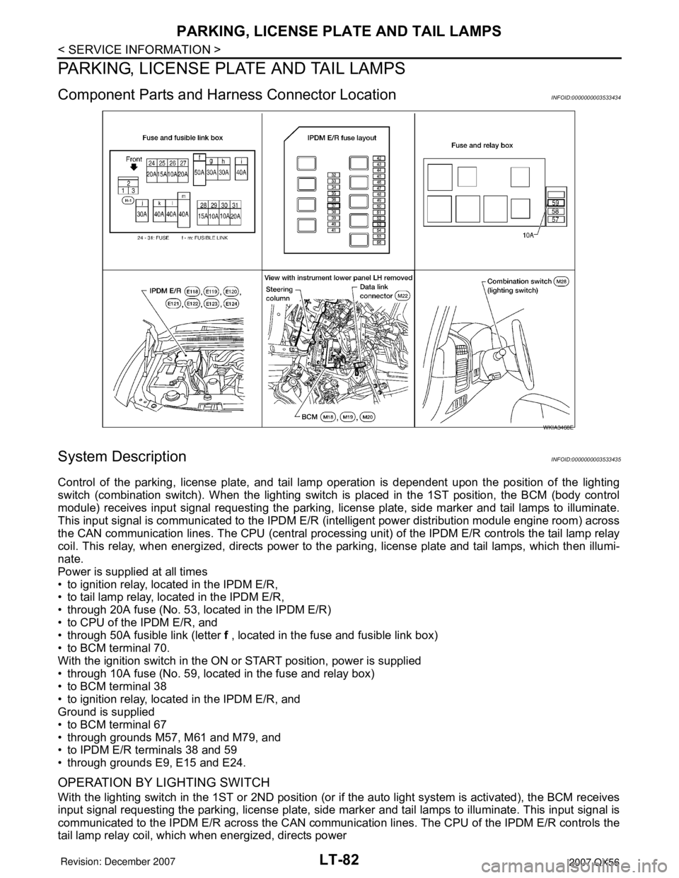
Component Parts and Harness Connector LocationINFOID:0000000003533434
System DescriptionINFOID:0000000003533435
Control of the parking, license plate, and tail lamp operation is dependent upon the position of the lighting
switch (combination switch). When the lighting switch is placed in the 1ST position, the BCM (body control
module) receives input signal requesting the parking, license plate, side marker and tail lamps to illuminate.
This input signal is communicated to the IPDM E/R (intelligent power distribution module engine room) across
the CAN communication lines. The CPU (central processing unit) of the IPDM E/R controls the tail lamp relay
coil. This relay, when energized, directs power to the parking, license plate and tail lamps, which then illumi-
nate.
Power is supplied at all times
• to ignition relay, located in the IPDM E/R,
• to tail lamp relay, located in the IPDM E/R,
• through 20A fuse (No. 53, located in the IPDM E/R)
• to CPU of the IPDM E/R, and
• through 50A fusible link (letter f , located in the fuse and fusible link box)
• to BCM terminal 70.
With the ignition switch in the ON or START position, power is supplied
• through 10A fuse (No. 59, located in the fuse and relay box)
• to BCM terminal 38
• to ignition relay, located in the IPDM E/R, and
Ground is supplied
• to BCM terminal 67
• through grounds M57, M61 and M79, and
• to IPDM E/R terminals 38 and 59
• through grounds E9, E15 and E24.
OPERATION BY LIGHTING SWITCH
With the lighting switch in the 1ST or 2ND position (or if the auto light system is activated), the BCM receives
input signal requesting the parking, license plate, side marker and tail lamps to illuminate. This input signal is
communicated to the IPDM E/R across the CAN communication lines. The CPU of the IPDM E/R controls the
tail lamp relay coil, which when energized, directs power
WKIA3468E