2007 INFINITI QX56 fuse box
[x] Cancel search: fuse boxPage 2476 of 3061
PG-74
< SERVICE INFORMATION >
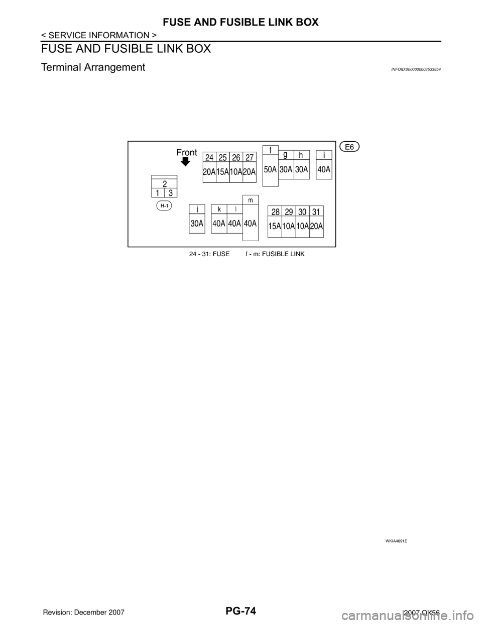
FUSE AND FUSIBLE LINK BOX
FUSE AND FUSIBLE LINK BOX
Terminal ArrangementINFOID:0000000003533854
WKIA4691E
Page 2477 of 3061
FUSE AND RELAY BOX
PG-75
< SERVICE INFORMATION >
C
D
E
F
G
H
I
J
L
MA
B
PG
N
O
P
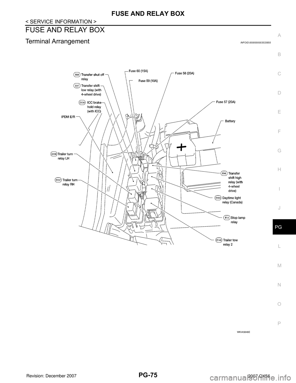
FUSE AND RELAY BOX
Terminal ArrangementINFOID:0000000003533855
WKIA5846E
Page 2542 of 3061
RF-10
< SERVICE INFORMATION >
SUNROOF
SUNROOF
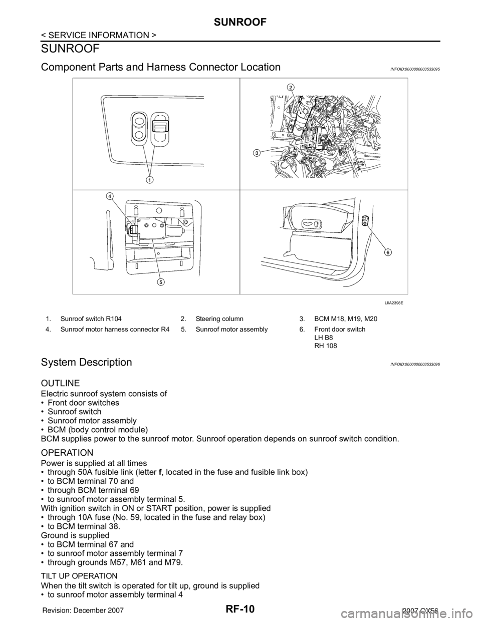
Component Parts and Harness Connector LocationINFOID:0000000003533095
System DescriptionINFOID:0000000003533096
OUTLINE
Electric sunroof system consists of
• Front door switches
• Sunroof switch
• Sunroof motor assembly
• BCM (body control module)
BCM supplies power to the sunroof motor. Sunroof operation depends on sunroof switch condition.
OPERATION
Power is supplied at all times
• through 50A fusible link (letter f, located in the fuse and fusible link box)
• to BCM terminal 70 and
• through BCM terminal 69
• to sunroof motor assembly terminal 5.
With ignition switch in ON or START position, power is supplied
• through 10A fuse (No. 59, located in the fuse and relay box)
• to BCM terminal 38.
Ground is supplied
• to BCM terminal 67 and
• to sunroof motor assembly terminal 7
• through grounds M57, M61 and M79.
TILT UP OPERATION
When the tilt switch is operated for tilt up, ground is supplied
• to sunroof motor assembly terminal 4
LIIA2398E
1. Sunroof switch R104 2. Steering column 3. BCM M18, M19, M20
4. Sunroof motor harness connector R4 5. Sunroof motor assembly 6. Front door switch
LH B8
RH 108
Page 2657 of 3061

STARTING SYSTEM
SC-9
< SERVICE INFORMATION >
C
D
E
F
G
H
I
J
L
MA
B
SC
N
O
P
STARTING SYSTEM
System DescriptionINFOID:0000000003533319
Power is supplied at all times
• through 40A fusible link (letter m , located in the fuse and fusible link box)
• to ignition switch terminal B.
With the ignition switch in the START position, power is supplied
• from ignition switch terminal ST
• to IPDM E/R terminal 21.
With the ignition switch in the ON or START position, power is supplied to IPDM E/R (intelligent power distribu-
tion module engine room) CPU.
With the selector lever in the P or N position, power is supplied
• through A/T assembly terminal 9
• to IPDM E/R terminal 48.
Ground is supplied at all times
• to IPDM E/R terminals 38 and 59
• through body grounds E9, E15 and E24.
Then the starter relay is turned on.
The IPDM E/R is energized and power is supplied
• from terminal 19 of the IPDM E/R
• to terminal 1 of the starter motor windings.
The starter motor plunger closes and provides a closed circuit between the battery and the starter motor. The
starter motor is grounded to the cylinder block. With power and ground supplied, the starter motor operates.
Page 2661 of 3061
STARTING SYSTEM
SC-13
< SERVICE INFORMATION >
C
D
E
F
G
H
I
J
L
MA
B
SC
N
O
P
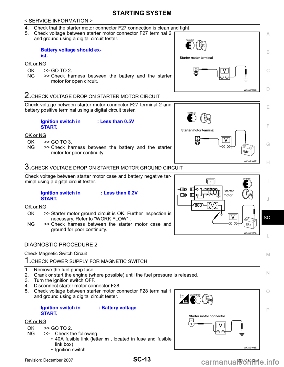
4. Check that the starter motor connector F27 connection is clean and tight.
5. Check voltage between starter motor connector F27 terminal 2
and ground using a digital circuit tester.
OK or NG
OK >> GO TO 2.
NG >> Check harness between the battery and the starter
motor for open circuit.
2.CHECK VOLTAGE DROP ON STARTER MOTOR CIRCUIT
Check voltage between starter motor connector F27 terminal 2 and
battery positive terminal using a digital circuit tester.
OK or NG
OK >> GO TO 3.
NG >> Check harness between the battery and the starter
motor for poor continuity.
3.CHECK VOLTAGE DROP ON STARTER MOTOR GROUND CIRCUIT
Check voltage between starter motor case and battery negative ter-
minal using a digital circuit tester.
OK or NG
OK >> Starter motor ground circuit is OK. Further inspection is
necessary. Refer to "WORK FLOW" .
NG >> Check harness between the starter motor case and
ground for poor continuity.
DIAGNOSTIC PROCEDURE 2
Check Magnetic Switch Circuit
1.CHECK POWER SUPPLY FOR MAGNETIC SWITCH
1. Remove the fuel pump fuse.
2. Crank or start the engine (where possible) until the fuel pressure is released.
3. Turn the ignition switch OFF.
4. Disconnect starter motor connector F28.
5. Check voltage between starter motor connector F28 terminal 1
and ground using a digital circuit tester.
OK or NG
OK >> GO TO 2.
NG >> Check the following.
• 40A fusible link (letter m , located in fuse and fusible
link box)
• Ignition switch Battery voltage should ex-
ist.
WKIA2105E
Ignition switch in
START.: Less than 0.5V
WKIA2106E
Ignition switch in
START.: Less than 0.2V
WKIA3437E
Ignition switch in
START.: Battery voltage
WKIA2108E
Page 2663 of 3061

CHARGING SYSTEM
SC-15
< SERVICE INFORMATION >
C
D
E
F
G
H
I
J
L
MA
B
SC
N
O
P
CHARGING SYSTEM
System DescriptionINFOID:0000000003533323
The generator provides DC voltage to operate the vehicle's electrical system and to keep the battery charged.
The voltage output is controlled by the IC regulator.
Power is supplied at all times to generator terminal 3 through
• 10A fuse (No. 30, located in the fuse and fusible link box).
Terminal 1 supplies power to charge the battery and operate the vehicle's electrical system. Output voltage is
controlled by the IC regulator at terminal 3 detecting the input voltage. A pulse width modulated (PWM) signal
is sent from terminal 37 of the IPDM E/R to terminal 4 of the generator. The ECM determines the duty cycle of
the power generation variable voltage control system. The charging circuit is protected by the 140A fusible link
[letter a, located in the fusible link box (battery)].
The generator is grounded through the engine.
With the ignition switch in the ON or START position, power is supplied
• through 10A fuse [No. 14, located in the fuse block (J/B)]
• to combination meter terminal 24 for the charge warning lamp.
Ground is supplied to terminal 13 of the combination meter through terminal 2 of the generator. With power
and ground supplied, the charge warning lamp will illuminate. When the generator is providing sufficient volt-
age with the engine running, the ground is opened and the charge warning lamp will go off. If the charge warn-
ing lamp illuminates with the engine running, a fault is indicated. The IC regulator warning function activates to
illuminate “CHARGE” warning lamp, if any of the following symptoms occur while generator is operating:
• Excessive voltage is produced.
• No voltage is produced.
POWER GENERATION VARIABLE VOLTAGE CONTROL SYSTEM
NOTE:
Power generation variable voltage control system has been adopted. By varying the voltage to the generator,
engine load due to power generation of the generator is reduced and fuel consumption is decreased.
Operation
• The battery current sensor detects the charging/discharging current of the battery. ECM judges the battery
condition based on this signal.
• ECM judges whether to control voltage according to the battery condition.
• ECM calculates the target power generation voltage according to the battery condition and sends the calcu-
lated value, through CAN lines, as the power generation command value to IPDM E/R.
• IPDM E/R converts the received power generation command value into the power generation command sig-
nal (PWM signal) and sends it to the IC regulator.
• The IC regulator performs final control over the power generation voltage.
• When there is no power generation command signal, the generator performs the normal power generation
according to the characteristic of the IC regulator.
NOTE:
When any malfunction is detected in the power generation variable voltage control system, power generation
is performed according to the characteristic of the IC regulator in the generator.
PKIB4908E
Page 2874 of 3061
TF-52
< SERVICE INFORMATION >
TROUBLE DIAGNOSIS FOR SYSTEM
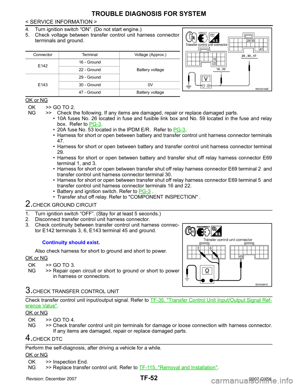
4. Turn ignition switch “ON”. (Do not start engine.)
5. Check voltage between transfer control unit harness connector
terminals and ground.
OK or NG
OK >> GO TO 2.
NG >> Check the following. If any items are damaged, repair or replace damaged parts.
• 10A fuses No. 26 located in fuse and fusible link box and No. 59 located in the fuse and relay
box. Refer to PG-3
.
• 20A fuse No. 53 located in the IPDM E/R. Refer to PG-3
.
• Harness for short or open between battery and transfer control unit harness connector terminals
47.
• Harness for short or open between battery and transfer control unit harness connector terminal
29.
• Harness for short or open between battery and transfer shut off relay harness connector E69
terminal 1, and 3.
• Harness for short or open between transfer shut off relay harness connector E69 terminal 2 and
transfer control unit harness connector terminal 30.
• Harness for short or open between transfer shut off relay harness connector E69 terminal 5 and
transfer control unit harness connector terminals 16 and 22.
• Battery and ignition switch. Refer to PG-3
.
• Transfer shut off relay. Refer to "COMPONENT INSPECTION" .
2.CHECK GROUND CIRCUIT
1. Turn ignition switch “OFF”. (Stay for at least 5 seconds.)
2. Disconnect transfer control unit harness connector.
3. Check continuity between transfer control unit harness connec-
tor E142 terminals 3, 6, E143 terminal 45 and ground.
Also check harness for short to ground and short to power.
OK or NG
OK >> GO TO 3.
NG >> Repair open circuit or short to ground or short to power
in harness or connectors.
3.CHECK TRANSFER CONTROL UNIT
Check transfer control unit input/output signal. Refer to TF-35, "
Transfer Control Unit Input/Output Signal Ref-
erence Value".
OK or NG
OK >> GO TO 4.
NG >> Check transfer control unit pin terminals for damage or loose connection with harness connector.
If any items are damaged, repair or replace damaged parts.
4.CHECK DTC
Perform the self-diagnosis, after driving a vehicle for a while.
OK or NG
OK >> Inspection End.
NG >> Replace transfer control unit. Refer to TF-115, "
Removal and Installation".
Connector Terminal Voltage (Approx.)
E14216 - Ground
Battery voltage 22 - Ground
E14329 - Ground
30 - Ground 0V
47 - Ground Battery voltage
WDIA0166E
Continuity should exist.
SDIA2691E
Page 2896 of 3061
TF-74
< SERVICE INFORMATION >
TROUBLE DIAGNOSIS FOR SYSTEM
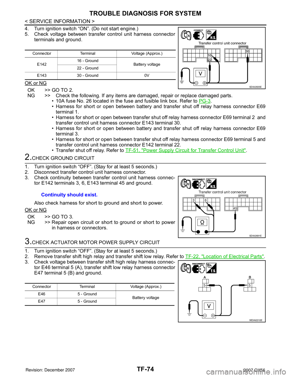
4. Turn ignition switch “ON”. (Do not start engine.)
5. Check voltage between transfer control unit harness connector
terminals and ground.
OK or NG
OK >> GO TO 2.
NG >> Check the following. If any items are damaged, repair or replace damaged parts.
• 10A fuse No. 26 located in the fuse and fusible link box. Refer to PG-3
.
• Harness for short or open between battery and transfer shut off relay harness connector E69
terminal 1.
• Harness for short or open between transfer shut off relay harness connector E69 terminal 2 and
transfer control unit harness connector E143 terminal 30.
• Harness for short or open between battery and transfer shut off relay harness connector E69
terminal 3.
• Harness for short or open between transfer shut off relay harness connector E69 terminal 5 and
transfer control unit harness connector E142 terminal 22.
• Transfer shut off relay. Refer to TF-51, "
Power Supply Circuit for Transfer Control Unit".
2.CHECK GROUND CIRCUIT
1. Turn ignition switch “OFF”. (Stay for at least 5 seconds.)
2. Disconnect transfer control unit harness connector.
3. Check continuity between transfer control unit harness connec-
tor E142 terminals 3, 6, E143 terminal 45 and ground.
Also check harness for short to ground and short to power.
OK or NG
OK >> GO TO 3.
NG >> Repair open circuit or short to ground or short to power
in harness or connectors.
3.CHECK ACTUATOR MOTOR POWER SUPPLY CIRCUIT
1. Turn ignition switch “OFF”. (Stay for at least 5 seconds.)
2. Remove transfer shift high relay and transfer shift low relay. Refer to TF-22, "
Location of Electrical Parts".
3. Check voltage between transfer shift high relay harness connec-
tor E46 terminal 5 (A), transfer shift low relay harness connector
E47 terminal 5 (B) and ground.
Connector Terminal Voltage (Approx.)
E14216 - Ground
Battery voltage
22 - Ground
E143 30 - Ground 0V
SDIA2835E
Continuity should exist.
SDIA2691E
Connector Terminal Voltage (Approx.)
E46 5 - Ground
Battery voltage
E47 5 - Ground
WDIA0310E