2007 INFINITI QX56 ignition
[x] Cancel search: ignitionPage 1023 of 3061

DI-12
< SERVICE INFORMATION >
COMBINATION METERS
Self-Diagnosis Mode of Combination Meter
INFOID:0000000003533486
SELF-DIAGNOSIS FUNCTION
The following items can be checked during Combination Meter Self-Diagnosis Mode.
• Gauge sweep and present gauge values.
• Illuminates all odometer, fuel, and engine temperature segments.
• Illuminates all micro controlled lamps/LE D's regardless of switch configuration.
• Displays estimated present battery voltage.
• Displays seat belt buckle switch LH status.
HOW TO INITIATE COMBINATION METER SELF- DIAGNOSIS MODE
NOTE:
Once entered, Combination Meter Self-Diagnosis Mode will function with the ignition switch in ON or START.
Combination Meter Self-Diagnosis Mode will exit upon turning the ignition switch to OFF or ACC.
To initiate Combination Meter Self-Diagnosis Mode, refer to the following procedure.
1. Turn the ignition switch ON, while holding the odom eter/trip meter switch for 5 - 8 seconds. When the
diagnosis function is activated the odometer/trip meter will display tESt.
NOTE:
Check combination meter power supply and ground ci rcuit when self-diagnosis mode of combination
meter does not start. Refer to DI-16, "
Power Supply and Ground Circuit Inspection". Replace combination
meter if normal. Refer to IP-10, "
Removal and Installation".
COMBINATION METER SELF-DIAGNOSIS MODE FUNCTIONS
To interpret Combination Meter Self-Diagnosis Mode functions, refer to the following table.
37 W/L Washer fluid level switch ON Washer fluid level low 0
Washer fluid level normal Battery voltage
Te r m i n a l
No. Wire
color Item Condition
Reference value (V)
(Approx.)
Ignition
switch Operation or condition
Event Odometer Display Description of Test/Data Notes:
Odometer/trip meter A/B
switch held from 5 to 8
seconds (or until re-
leased) tESt Initiating self-diagnosis mode
Odometer/trip meter A/B
switch engaged and re-
leased = next test re-
quested rXXXX, FAILReturn to normal opera-
tion of all lamps/LEDs and
displays hex ROM rev. If a
ROM checksum fault ex-
ists, display alternates be-
tween "r XXXX" and
"FAIL".
Next test requested nrXXXX Displays hex ROM rev as
stored in NVM.
Next test requested Sc1XX Displays 8-bit software
configuration value in Hex
format.Bit Coding
7-3 = reserved for future use
2 = TCS/VDC 0 = not present
1 = present
1 = Shift type 0 = Column shift
1 = Floor shift
0 = ICC 0 = not present
1 = present
Next test requested Sc2XX Displays 8-bit software
configuration value in Hex
format.Bit coding
7-0 = Reserved for future use
Page 1026 of 3061

COMBINATION METERSDI-15
< SERVICE INFORMATION >
C
DE
F
G H
I
J
L
M A
B
DI
N
O P
How to Proceed with Trouble DiagnosisINFOID:0000000003533487
1. Confirm the symptom or customer complaint.
2. Perform preliminary check. Refer to DI-15, "
Preliminary Check".
3. According to the symptom chart, repair or replace the cause of the symptom.
4. Does the meter operate normally? If so, go to 5. If not, go to 2.
5. Inspection End.
Preliminary CheckINFOID:0000000003533488
1.CHECK WARNING INDICATOR ILLUMINATION
1. Turn ignition switch ON.
2. Make sure warning indicators (such as malfunction indicator lamp and oil pressure low/coolant tempera- ture high warning indicator) illuminate.
Do warning indicators illuminate?
YES >> GO TO 2.
NO >> Check ignition power supply system of combination meter. Refer to DI-16, "
Power Supply and
Ground Circuit Inspection".
2.CHECK OPERATION OF SELF-DIAGNOSIS MODE (COMBINATION METER)
Next test requested A04XXXA/D port A/D value (non-
ratioed).0-255
Next test requested A05XXX A/D port A/D value (non-
ratioed).
0-255
Next test requested A06XXX A/D port A/D value (non-
ratioed).0-255
Next test requested A07XXX A/D port A/D value (non-
ratioed).0-255
Next test requested A08XXX A/D port A/D value (non-
ratioed).
0-255
Next test requested A09XXX A/D port A/D value (non-
ratioed).0-255
Next test requested A10XXX A/D port A/D value (non-
ratioed).0-255
Next test requested A11XXX A/D port A/D value (non-
ratioed).
0-255
Next test requested A12XXX A/D port A/D value (non-
ratioed).0-255
Next test requested A13XXX A/D port A/D value (non-
ratioed).0-255
Next test requested A14XXX A/D port A/D value (non-
ratioed).
0-255
Next test requested A15XXX A/D port A/D value (non-
ratioed).0-255
Next test requested PA0-XX Hex value representing
state of A/D ports 0-7.
Next test requested PA1-XX Hex value representing
state of A/D ports 0-7.
Next test requested Thr-XXX Decimal value of ther-
mistor A/D reading.0-255
Next test requested rXXXX, FAIL Return to beginning of self-di-
agnosis.
Event Odometer Display Description of Test/Data Notes:
Page 1028 of 3061
COMBINATION METERSDI-17
< SERVICE INFORMATION >
C
DE
F
G H
I
J
L
M A
B
DI
N
O P
Refer to DI-9, "Wiring Diagram - METER -".
OK or NG
OK >> GO TO 2.
NG >> If fuse is blown, be sure to eliminate caus e of malfunction before installing new fuse. Refer to PG-
3.
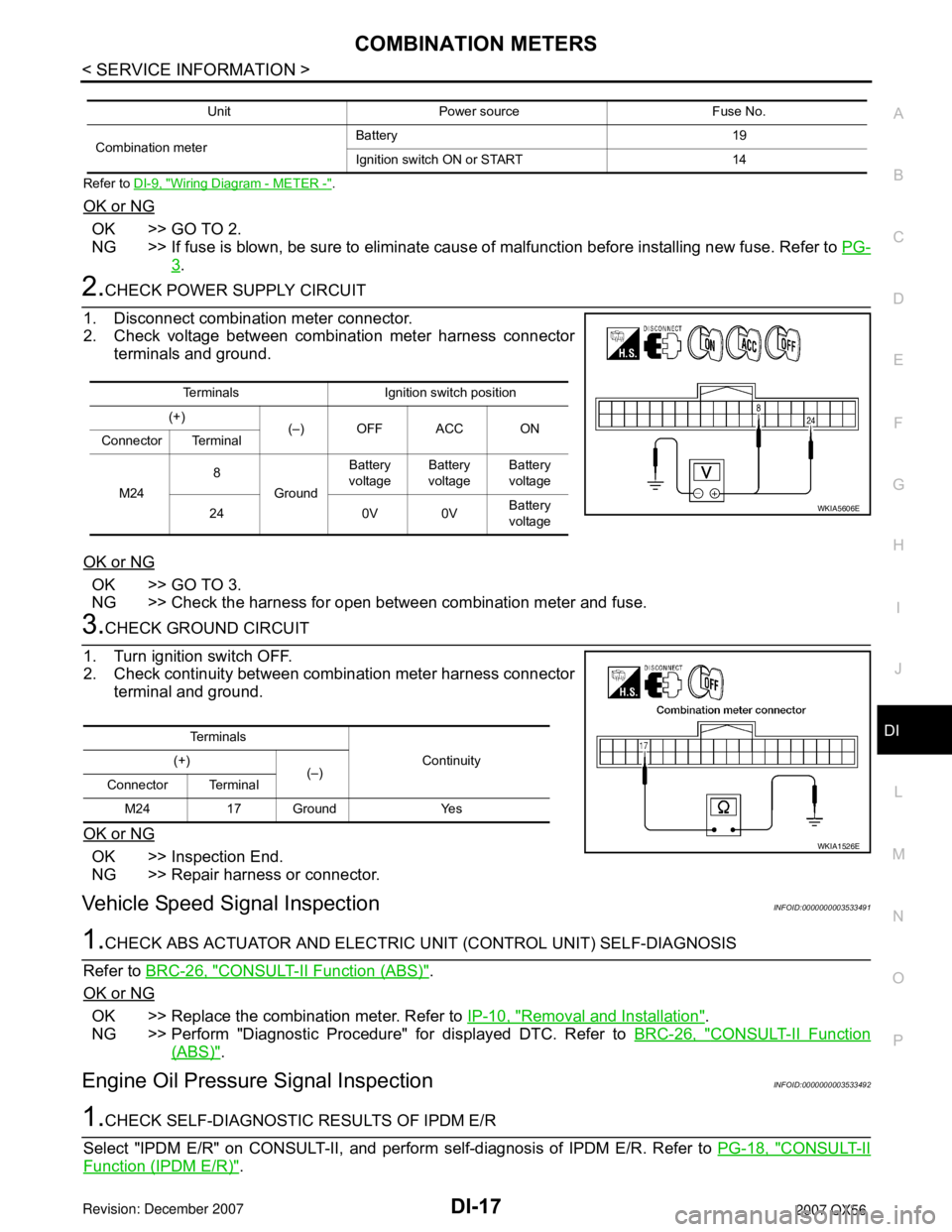
2.CHECK POWER SUPPLY CIRCUIT
1. Disconnect combination meter connector.
2. Check voltage between combination meter harness connector terminals and ground.
OK or NG
OK >> GO TO 3.
NG >> Check the harness for open between combination meter and fuse.
3.CHECK GROUND CIRCUIT
1. Turn ignition switch OFF.
2. Check continuity between combination meter harness connector terminal and ground.
OK or NG
OK >> Inspection End.
NG >> Repair harness or connector.
Vehicle Speed Signal InspectionINFOID:0000000003533491
1.CHECK ABS ACTUATOR AND ELECTRIC UNIT (CONTROL UNIT) SELF-DIAGNOSIS
Refer to BRC-26, "
CONSULT-II Function (ABS)".
OK or NG
OK >> Replace the combination meter. Refer to IP-10, "Removal and Installation".
NG >> Perform "Diagnostic Procedure" for displayed DTC. Refer to BRC-26, "
CONSULT-II Function
(ABS)".
Engine Oil Pressure Signal InspectionINFOID:0000000003533492
1.CHECK SELF-DIAGNOSTIC RESULTS OF IPDM E/R
Select "IPDM E/R" on CONSULT-II, and perform self-diagnosis of IPDM E/R. Refer to PG-18, "
CONSULT-II
Function (IPDM E/R)".
Unit Power source Fuse No.
Combination meter Battery 19
Ignition switch ON or START 14
Terminals Ignition switch position
(+) (–) OFF ACC ON
Connector Terminal
M24 8
Ground Battery
voltage Battery
voltage Battery
voltage
24 0V 0V Battery
voltage
WKIA5606E
Te r m i n a l s
Continuity
(+)
(–)
Connector Terminal
M24 17 Ground Yes
WKIA1526E
Page 1029 of 3061
DI-18
< SERVICE INFORMATION >
COMBINATION METERS
Self-diagnostic results content
No malfunction detected>>GO TO 2.
Malfunction detected>>GO TO PG-18, "
CONSULT-II Function (IPDM E/R)".
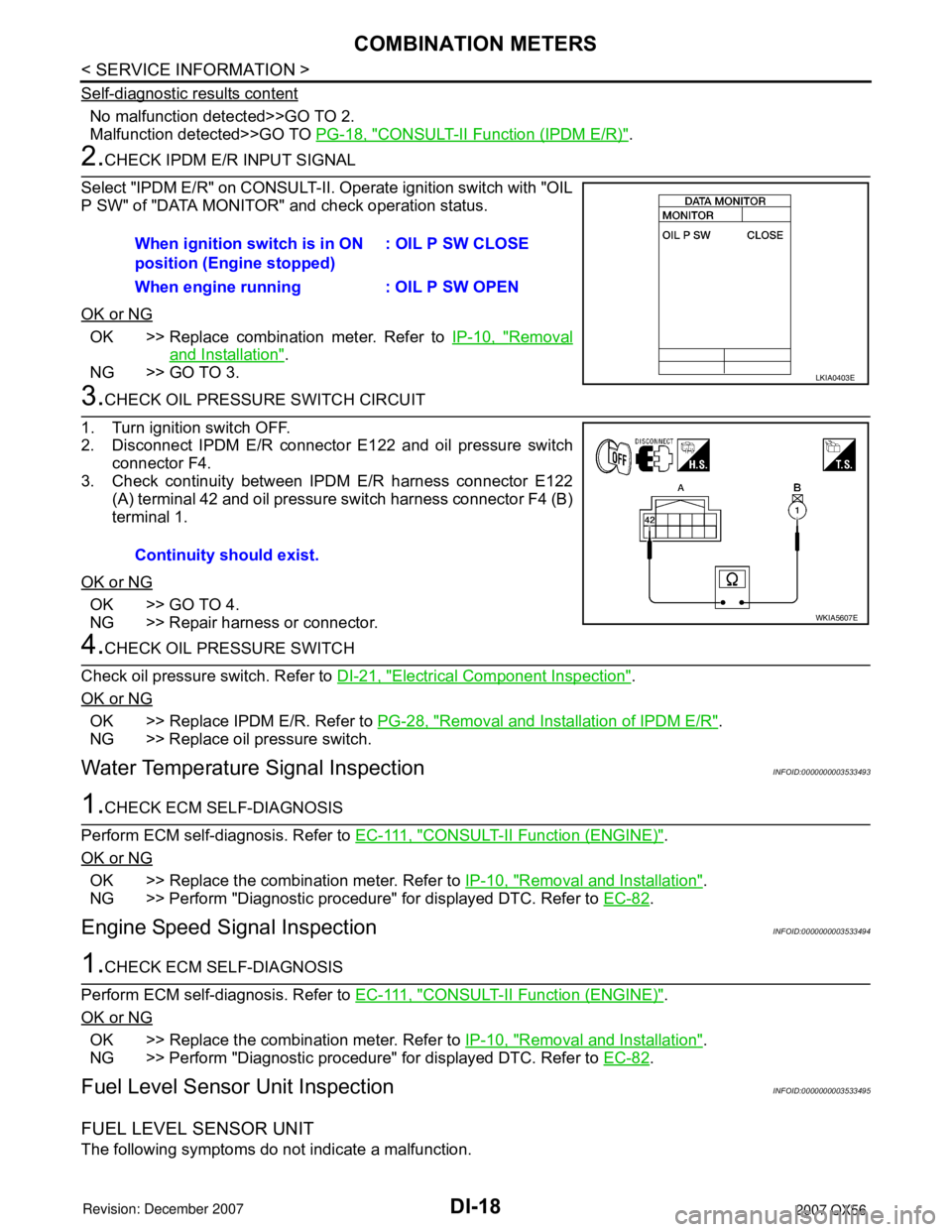
2.CHECK IPDM E/R INPUT SIGNAL
Select "IPDM E/R" on CONSULT-II. Operate ignition switch with "OIL
P SW" of "DATA MONITOR" and check operation status.
OK or NG
OK >> Replace combination meter. Refer to IP-10, "Removal
and Installation".
NG >> GO TO 3.
3.CHECK OIL PRESSURE SWITCH CIRCUIT
1. Turn ignition switch OFF.
2. Disconnect IPDM E/R connector E122 and oil pressure switch
connector F4.
3. Check continuity between IPDM E/R harness connector E122 (A) terminal 42 and oil pressure switch harness connector F4 (B)
terminal 1.
OK or NG
OK >> GO TO 4.
NG >> Repair harness or connector.
4.CHECK OIL PRESSURE SWITCH
Check oil pressure switch. Refer to DI-21, "
Electrical Component Inspection".
OK or NG
OK >> Replace IPDM E/R. Refer to PG-28, "Removal and Installation of IPDM E/R".
NG >> Replace oil pressure switch.
Water Temperature Signal InspectionINFOID:0000000003533493
1.CHECK ECM SELF-DIAGNOSIS
Perform ECM self-diagnosis. Refer to E C - 111 , "
CONSULT-II Function (ENGINE)".
OK or NG
OK >> Replace the combination meter. Refer to IP-10, "Removal and Installation".
NG >> Perform "Diagnostic procedure" for displayed DTC. Refer to EC-82
.
Engine Speed Signal InspectionINFOID:0000000003533494
1.CHECK ECM SELF-DIAGNOSIS
Perform ECM self-diagnosis. Refer to E C - 111 , "
CONSULT-II Function (ENGINE)".
OK or NG
OK >> Replace the combination meter. Refer to IP-10, "Removal and Installation".
NG >> Perform "Diagnostic procedure" for displayed DTC. Refer to EC-82
.
Fuel Level Sensor Unit InspectionINFOID:0000000003533495
FUEL LEVEL SENSOR UNIT
The following symptoms do not indicate a malfunction.When ignition switch is in ON
position (Engine stopped)
: OIL P SW CLOSE
When engine running : OIL P SW OPEN
LKIA0403E
Continuity should exist.
WKIA5607E
Page 1030 of 3061
COMBINATION METERSDI-19
< SERVICE INFORMATION >
C
DE
F
G H
I
J
L
M A
B
DI
N
O P
• Depending on vehicle position or driving circumstance, the fuel in the tank shifts and the indication may fluc-
tuate.
• If the vehicle is fueled with the ignition switch ON, the indication will update slowly.
• If the vehicle is tilted when the ignition switch is turned ON, fuel in the tank may flow to one direction result-
ing in a change of reading.
LOW-FUEL WARNING LAMP
Depending on vehicle posture or driving circumstances, the fuel level in the tank varies, and the warning lamp
ON timing may be changed.
1.CHECK SELF-DIAGNOSIS
Perform the combination meter self-diagnosis. Refer to DI-12, "
Self-Diagnosis Mode of Combination Meter".
OK or NG
OK >> GO TO 2.
NG >> Replace the combination meter. Refer to IP-10, "
Removal and Installation".
2.CHECK HARNESS CONNECTOR
1. Turn the ignition switch OFF.
2. Check combination meter and fuel level sensor unit and fuel pump terminals (meter-side, and harness-
side) for poor connection.
OK or NG
OK >> GO TO 3.
NG >> Repair or replace terminals or connectors.
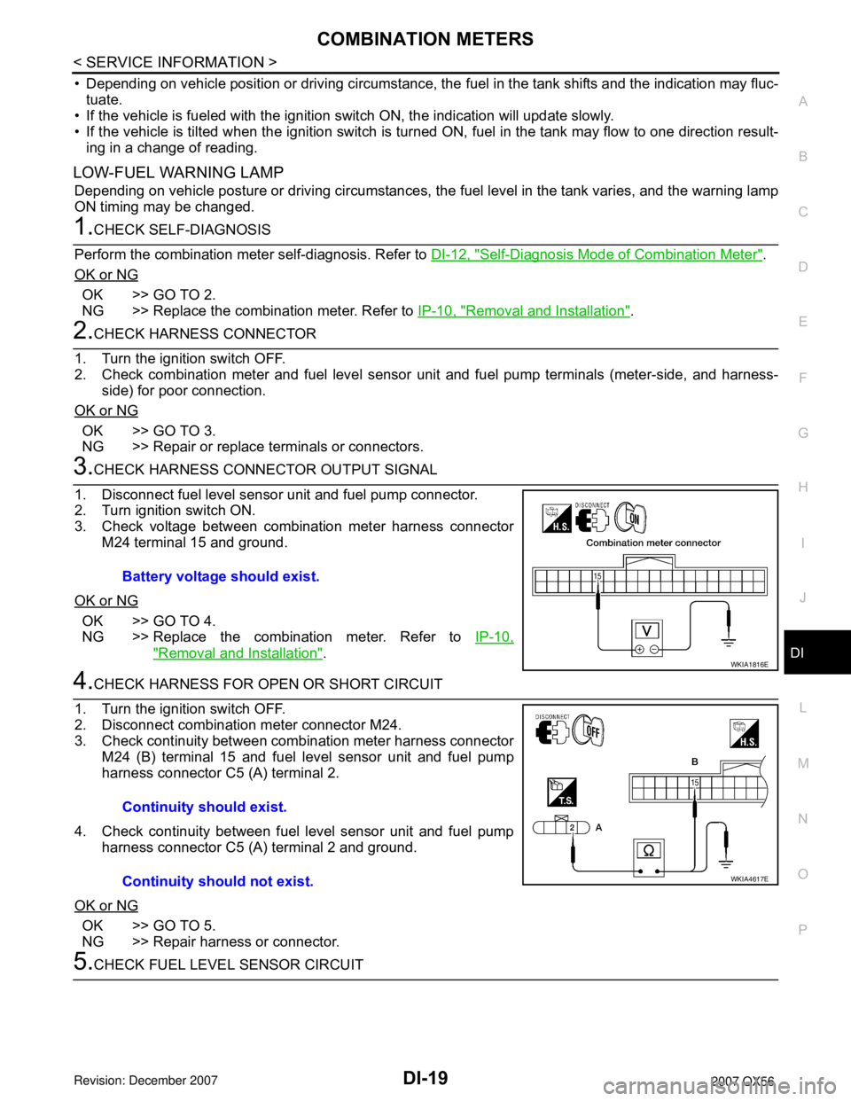
3.CHECK HARNESS CONNECTOR OUTPUT SIGNAL
1. Disconnect fuel level sensor unit and fuel pump connector.
2. Turn ignition switch ON.
3. Check voltage between combination meter harness connector M24 terminal 15 and ground.
OK or NG
OK >> GO TO 4.
NG >> Replace the combination meter. Refer to IP-10,
"Removal and Installation".
4.CHECK HARNESS FOR OPEN OR SHORT CIRCUIT
1. Turn the ignition switch OFF.
2. Disconnect combination meter connector M24.
3. Check continuity between combination meter harness connector M24 (B) terminal 15 and fuel level sensor unit and fuel pump
harness connector C5 (A) terminal 2.
4. Check continuity between fuel level sensor unit and fuel pump harness connector C5 (A) terminal 2 and ground.
OK or NG
OK >> GO TO 5.
NG >> Repair harness or connector.
5.CHECK FUEL LEVEL SENSOR CIRCUIT Battery voltage should exist.
WKIA1816E
Continuity should exist.
Continuity should not exist.
WKIA4617E
Page 1031 of 3061
DI-20
< SERVICE INFORMATION >
COMBINATION METERS
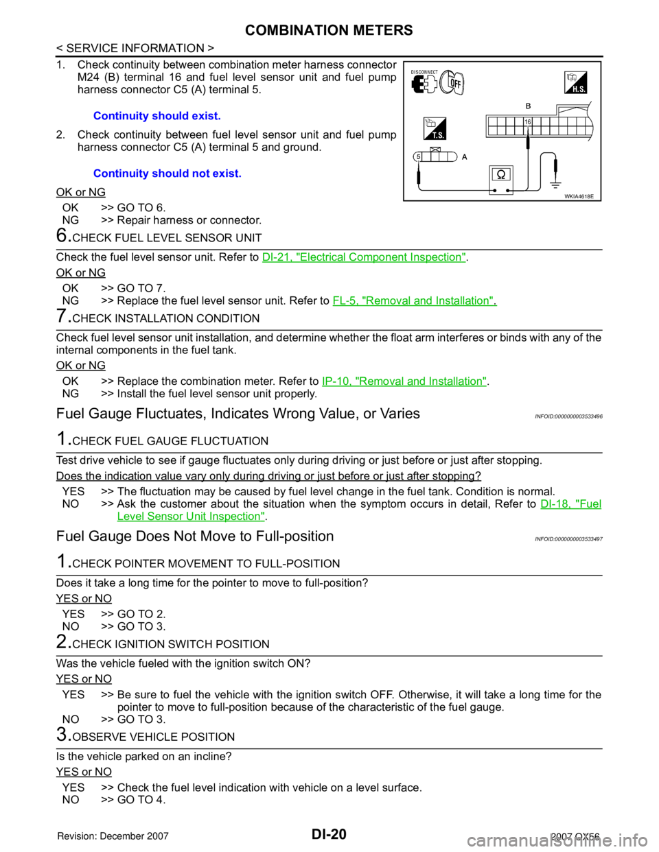
1. Check continuity between combination meter harness connectorM24 (B) terminal 16 and fuel level sensor unit and fuel pump
harness connector C5 (A) terminal 5.
2. Check continuity between fuel level sensor unit and fuel pump harness connector C5 (A) terminal 5 and ground.
OK or NG
OK >> GO TO 6.
NG >> Repair harness or connector.
6.CHECK FUEL LEVEL SENSOR UNIT
Check the fuel level sensor unit. Refer to DI-21, "
Electrical Component Inspection".
OK or NG
OK >> GO TO 7.
NG >> Replace the fuel level sensor unit. Refer to FL-5, "
Removal and Installation".
7.CHECK INSTALLATION CONDITION
Check fuel level sensor unit installation, and determine whet her the float arm interferes or binds with any of the
internal components in the fuel tank.
OK or NG
OK >> Replace the combination meter. Refer to IP-10, "Removal and Installation".
NG >> Install the fuel level sensor unit properly.
Fuel Gauge Fluctuat es, Indicates Wrong Value, or VariesINFOID:0000000003533496
1.CHECK FUEL GAUGE FLUCTUATION
Test drive vehicle to see if gauge fluctuates only during driving or just before or just after stopping.
Does the indication value vary only during driving or just before or just after stopping?
YES >> The fluctuation may be caused by fuel leve l change in the fuel tank. Condition is normal.
NO >> Ask the customer about the situation when the symptom occurs in detail, Refer to DI-18, "
Fuel
Level Sensor Unit Inspection".
Fuel Gauge Does Not Move to Full-positionINFOID:0000000003533497
1.CHECK POINTER MOVEME NT TO FULL-POSITION
Does it take a long time for the pointer to move to full-position?
YES or NO
YES >> GO TO 2.
NO >> GO TO 3.
2.CHECK IGNITION SWITCH POSITION
Was the vehicle fueled with the ignition switch ON?
YES or NO
YES >> Be sure to fuel the vehicle with the ignition s witch OFF. Otherwise, it will take a long time for the
pointer to move to full-position because of the characteristic of the fuel gauge.
NO >> GO TO 3.
3.OBSERVE VEHICLE POSITION
Is the vehicle parked on an incline?
YES or NO
YES >> Check the fuel level indication with vehicle on a level surface.
NO >> GO TO 4. Continuity should exist.
Continuity should not exist.
WKIA4618E
Page 1033 of 3061
DI-22
< SERVICE INFORMATION >
COMPASS AND THERMOMETER
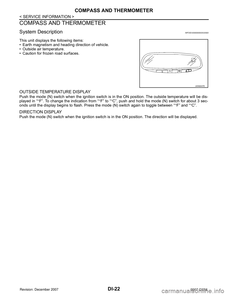
COMPASS AND THERMOMETER
System DescriptionINFOID:0000000003533500
This unit displays the following items:
• Earth magnetism and heading direction of vehicle.
• Outside air temperature.
• Caution for frozen road surfaces.
OUTSIDE TEMPERATURE DISPLAY
Push the mode (N) switch when the ignition switch is in the ON position. The outside temperature will be dis-
played in “°F”. To change the indication from “°F” to “°C”, push and hold the mode (N) switch for about 3 sec-
onds until the display begins to flash. Press the mode (N) switch again to toggle between “°F” and “°C”.
DIRECTION DISPLAY
Push the mode (N) switch when the ignition switch is in the ON position. The direction will be displayed.
LKIA0447E
Page 1035 of 3061

DI-24
< SERVICE INFORMATION >
COMPASS AND THERMOMETER
1. Turn the ignition switch to the ON position.
2. Cool down ambient sensor 2 with water or ice.
Does the indicated temperature drop?
YES >> GO TO 2.
NO >> The system is malfunctioning. Check the system following “INSPECTION/COMPASS AND THER-
MOMETER”. Refer to "INSPECTION/COMPASS AND THERMOMETER".
2.WARM UP CHECK
1. Leave the vehicle for 10 minutes.
2. With the ignition switch in the ON position, disconnect and reconnect ambient sensor 2 connector.
Does the indicated temperature rise?
YES >> The system is OK.
NO >> The system is malfunctioning. Check the system following “INSPECTION/COMPASS AND THER-
MOMETER”. Refer to "INSPECTION/COMPASS AND THERMOMETER".
INSPECTION/COMPASS AND THERMOMETER
Calibration Procedure for CompassINFOID:0000000003533503
The difference between magnetic North and geographical North can sometimes be great enough to cause
false compass readings. In order for the compass to operate accurately in a particular zone, it must be cali-
brated using the following procedure.
Symptom Possible causes Repair order
No display at all 1. 10A fuse.
2. Ground circuit.
3. auto anti-dazzling inside mirror.1. Check 10A fuse [No. 12, located in fuse block (J/B)].
Turn the ignition switch ON and verify that battery positive
voltage is at terminal 6 of auto anti-dazzling inside mirror.
2. Check ground circuit for auto anti-dazzling inside mirror.
3. Replace auto anti-dazzling inside mirror.
Forward direction indi-
cation slips off the mark
or incorrect.1. In manual correction mode (Bar
and display vanish).
2. Zone variation change is not
done.1. Drive the vehicle and turn at an angle of 90°.
2. Perform the zone variation change.
Displays wrong temper-
ature when ambient
temperature is between
−40°C (−40°F) and
55°C (130°F)1. Check operation.
2. Ambient sensor 2 circuit.
3. Ambient sensor 2.
4. Auto anti-dazzling inside mirror.1. Perform preliminary check shown above.
2. Check harness for open or short between ambient sensor 2
and auto anti-dazzling inside mirror.
3. Replace ambient sensor 2.
4. Replace auto anti-dazzling inside mirror.
Displays SC or OC 1. Ambient sensor 2 circuit.
2. Ambient sensor 2.
3. Auto anti-dazzling inside mirror.1. Check harness for open or short between ambient sensor 2
and auto anti-dazzling inside mirror.
2. Replace ambient sensor 2.
3. Replace auto anti-dazzling inside mirror.