2007 INFINITI QX56 ignition
[x] Cancel search: ignitionPage 1076 of 3061
REAR VIEW MONITOR
DI-65
< SERVICE INFORMATION >
C
D
E
F
G
H
I
J
L
MA
B
DI
N
O
P
CONSULT-II START PROCEDURE
Refer to GI-36, "CONSULT-II Start Procedure".
WORK SUPPORT
Refer to DI-65, "Side Distance Guideline Correction" for details.
DATA MONITOR
Display Item List
Side Distance Guideline CorrectionINFOID:0000000003533545
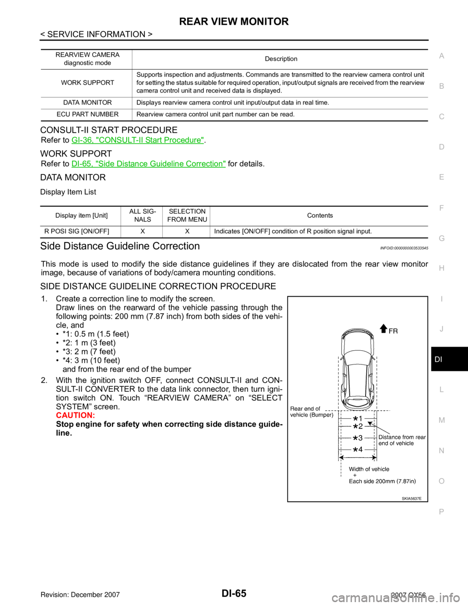
This mode is used to modify the side distance guidelines if they are dislocated from the rear view monitor
image, because of variations of body/camera mounting conditions.
SIDE DISTANCE GUIDELINE CORRECTION PROCEDURE
1. Create a correction line to modify the screen.
Draw lines on the rearward of the vehicle passing through the
following points: 200 mm (7.87 inch) from both sides of the vehi-
cle, and
• *1: 0.5 m (1.5 feet)
• *2: 1 m (3 feet)
• *3: 2 m (7 feet)
• *4: 3 m (10 feet)
and from the rear end of the bumper
2. With the ignition switch OFF, connect CONSULT-II and CON-
SULT-II CONVERTER to the data link connector, then turn igni-
tion switch ON. Touch “REARVIEW CAMERA” on “SELECT
SYSTEM” screen.
CAUTION:
Stop engine for safety when correcting side distance guide-
line.
REARVIEW CAMERA
diagnostic modeDescription
WORK SUPPORTSupports inspection and adjustments. Commands are transmitted to the rearview camera control unit
for setting the status suitable for required operation, input/output signals are received from the rearview
camera control unit and received data is displayed.
DATA MONITOR Displays rearview camera control unit input/output data in real time.
ECU PART NUMBER Rearview camera control unit part number can be read.
Display item [Unit]ALL SIG-
NALSSELECTION
FROM MENUContents
R POSI SIG [ON/OFF] X X Indicates [ON/OFF] condition of R position signal input.
SKIA5637E
Page 1078 of 3061
REAR VIEW MONITOR
DI-67
< SERVICE INFORMATION >
C
D
E
F
G
H
I
J
L
MA
B
DI
N
O
P
Power Supply and Ground Circuit InspectionINFOID:0000000003533546
1.CHECK FUSES
Check for blown rear view camera system fuses.
OK or NG
OK >> GO TO 2.
NG >> If fuse is blown, be sure to eliminate cause of problem before installing new fuse. Refer to PG-3
.
2.CHECK POWER SUPPLY CIRCUIT
1. Disconnect rear view camera control unit connector.
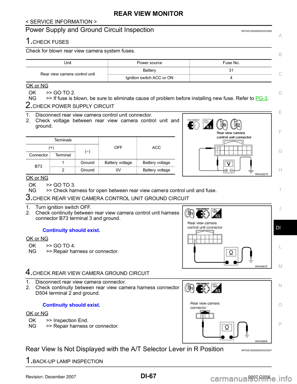
2. Check voltage between rear view camera control unit and
ground.
OK or NG
OK >> GO TO 3.
NG >> Check harness for open between rear view camera control unit and fuse.
3.CHECK REAR VIEW CAMERA CONTROL UNIT GROUND CIRCUIT
1. Turn ignition switch OFF.
2. Check continuity between rear view camera control unit harness
connector B73 terminal 3 and ground.
OK or NG
OK >> GO TO 4.
NG >> Repair harness or connector.
4.CHECK REAR VIEW CAMERA GROUND CIRCUIT
1. Disconnect rear view camera connector.
2. Check continuity between rear view camera harness connector
D504 terminal 2 and ground.
OK or NG
OK >> Inspection End.
NG >> Repair harness or connector.
Rear View Is Not Displayed with the A/T Selector Lever in R PositionINFOID:0000000003533547
1.BACK-UP LAMP INSPECTION
Unit Power source Fuse No.
Rear view camera control unitBattery 31
Ignition switch ACC or ON 4
Te r m i n a l s
OFF ACC (+)
(–)
Connector Terminal
B731 Ground Battery voltage Battery voltage
2 Ground 0V Battery voltage
WKIA2027E
Continuity should exist.
SKIA5081E
Continuity should exist.
SKIA5082E
Page 1079 of 3061

DI-68
< SERVICE INFORMATION >
REAR VIEW MONITOR
1. Turn ignition switch ON.
2. Shift A/T selector lever to R position.
Does back-up lamp illuminate?
YES >> GO TO 2.
NO >> Check back-up lamp system. Refer to LT- 8 0
.
2.CHECK REVERSE POSITION INPUT SIGNAL
With CONSULT-II
Select “DATA MONITOR” of “REARVIEW CAMERA”. Operate igni-
tion switch with “R POSI SIG” of “DATA MONITOR” and check oper-
ate status.
Without CONSULT-II
1. Turn ignition switch OFF.
2. Disconnect rear view camera control unit connector.
3. Turn ignition switch ON.
4. Shift A/T selector lever to R position.
5. Check voltage between rear view camera control unit harness
connector B73 terminal 4 and ground.
OK or NG
OK >> GO TO 3.
NG >> Check harness for open or short between rear view
camera control unit and back-up lamp relay.
3.CHECK DISPLAY CONTROL UNIT OUTPUT SIGNAL
1. Turn ignition switch OFF.
2. Disconnect rear view camera control unit connector.
3. Turn ignition switch ON.
4. Check voltage between rear view camera control unit harness
connector B73 terminal 5 and ground.
OK or NG
OK >> GO TO 5.
NG >> GO TO 4.
4.CHECK DISPLAY CONTROL UNIT CIRCUIT
SKIA7147E
Battery voltage should exist.
SKIA5086E
Voltage : Approx. 5V
SKIA7148E
Page 1080 of 3061
REAR VIEW MONITOR
DI-69
< SERVICE INFORMATION >
C
D
E
F
G
H
I
J
L
MA
B
DI
N
O
P
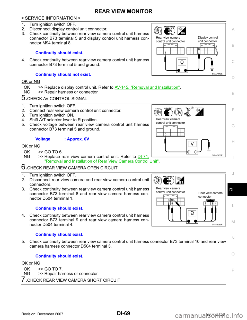
1. Turn ignition switch OFF.
2. Disconnect display control unit connector.
3. Check continuity between rear view camera control unit harness
connector B73 terminal 5 and display control unit harness con-
nector M94 terminal 8.
4. Check continuity between rear view camera control unit harness
connector B73 terminal 5 and ground.
OK or NG
OK >> Replace display control unit. Refer to AV-145, "Removal and Installation".
NG >> Repair harness or connector.
5.CHECK AV CONTROL SIGNAL
1. Turn ignition switch OFF.
2. Connect rear view camera control unit connector.
3. Turn ignition switch ON.
4. Shift A/T selector lever to R position.
5. Check voltage between rear view camera control unit harness
connector B73 terminal 5 and ground.
OK or NG
OK >> GO TO 6.
NG >> Replace rear view camera control unit. Refer to DI-71,
"Removal and Installation of Rear View Camera Control Unit".
6.CHECK REAR VIEW CAMERA OPEN CIRCUIT
1. Turn ignition switch OFF.
2. Disconnect rear view camera and rear view camera control unit
connectors.
3. Check continuity between rear view camera control unit harness
connector B73 terminal 8 and rear view camera harness con-
nector D504 terminal 1.
4. Check continuity between rear view camera control unit harness
connector B73 terminal 9 and rear view camera harness con-
nector D504 terminal 4.
5. Check continuity between rear view camera control unit harness connector B73 terminal 10 and rear view
camera harness connector D504 terminal 3.
OK or NG
OK >> GO TO 7.
NG >> Repair harness or connector.
7.CHECK REAR VIEW CAMERA SHORT CIRCUITContinuity should exist.
Continuity should not exist.
SKIA7149E
Voltage : Approx. 0V
SKIA7150E
Continuity should exist.
Continuity should exist.
Continuity should exist.
SKIA5095E
Page 1081 of 3061
DI-70
< SERVICE INFORMATION >
REAR VIEW MONITOR
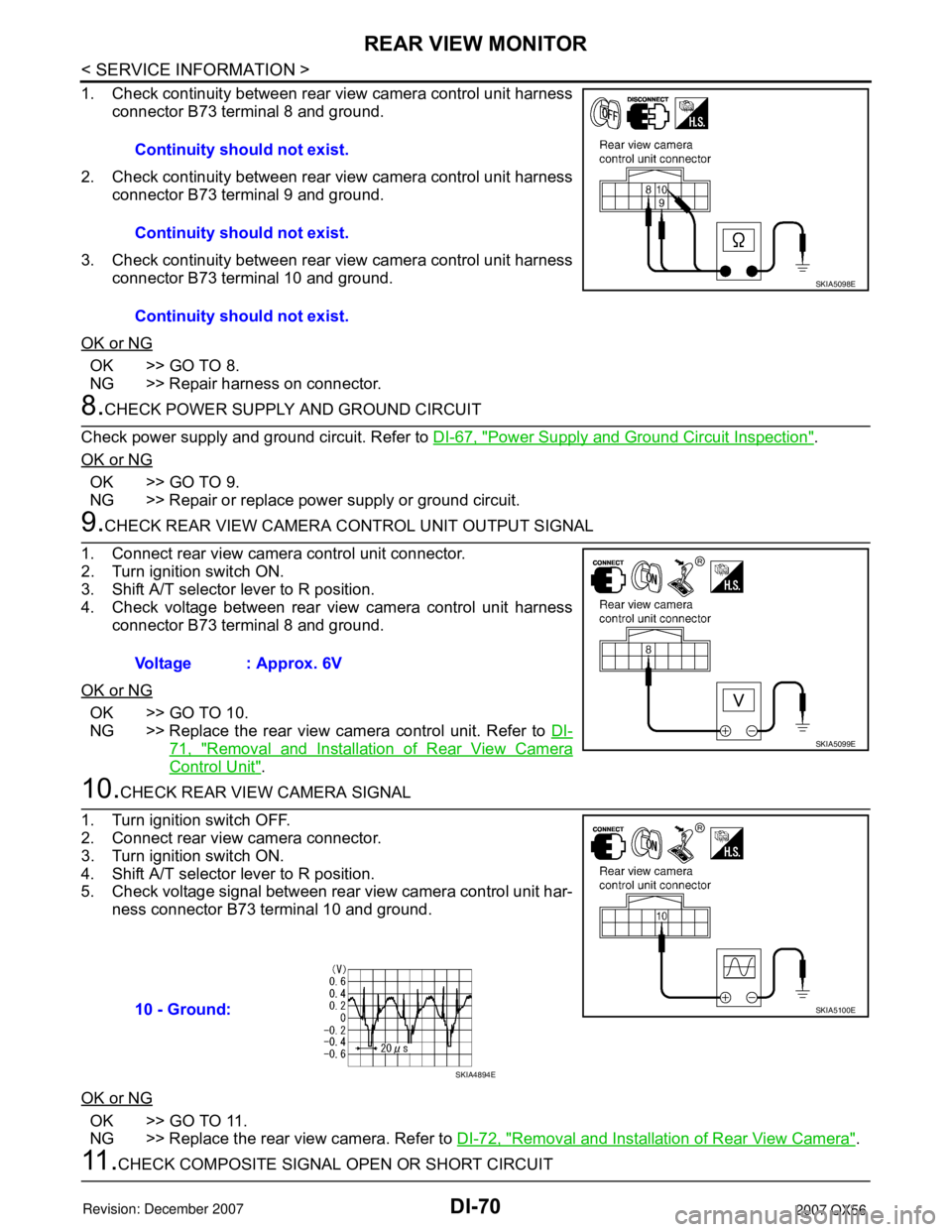
1. Check continuity between rear view camera control unit harness
connector B73 terminal 8 and ground.
2. Check continuity between rear view camera control unit harness
connector B73 terminal 9 and ground.
3. Check continuity between rear view camera control unit harness
connector B73 terminal 10 and ground.
OK or NG
OK >> GO TO 8.
NG >> Repair harness on connector.
8.CHECK POWER SUPPLY AND GROUND CIRCUIT
Check power supply and ground circuit. Refer to DI-67, "
Power Supply and Ground Circuit Inspection".
OK or NG
OK >> GO TO 9.
NG >> Repair or replace power supply or ground circuit.
9.CHECK REAR VIEW CAMERA CONTROL UNIT OUTPUT SIGNAL
1. Connect rear view camera control unit connector.
2. Turn ignition switch ON.
3. Shift A/T selector lever to R position.
4. Check voltage between rear view camera control unit harness
connector B73 terminal 8 and ground.
OK or NG
OK >> GO TO 10.
NG >> Replace the rear view camera control unit. Refer to DI-
71, "Removal and Installation of Rear View Camera
Control Unit".
10.CHECK REAR VIEW CAMERA SIGNAL
1. Turn ignition switch OFF.
2. Connect rear view camera connector.
3. Turn ignition switch ON.
4. Shift A/T selector lever to R position.
5. Check voltage signal between rear view camera control unit har-
ness connector B73 terminal 10 and ground.
OK or NG
OK >> GO TO 11.
NG >> Replace the rear view camera. Refer to DI-72, "
Removal and Installation of Rear View Camera".
11 .CHECK COMPOSITE SIGNAL OPEN OR SHORT CIRCUITContinuity should not exist.
Continuity should not exist.
Continuity should not exist.
SKIA5098E
Voltage : Approx. 6V
SKIA5099E
10 - Ground:SKIA5100E
SKIA4894E
Page 1082 of 3061
REAR VIEW MONITOR
DI-71
< SERVICE INFORMATION >
C
D
E
F
G
H
I
J
L
MA
B
DI
N
O
P
1. Turn ignition switch OFF.
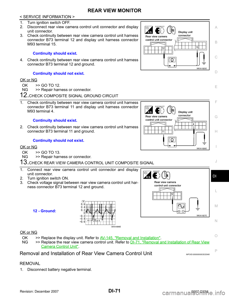
2. Disconnect rear view camera control unit connector and display
unit connector.
3. Check continuity between rear view camera control unit harness
connector B73 terminal 12 and display unit harness connector
M93 terminal 15.
4. Check continuity between rear view camera control unit harness
connector B73 terminal 12 and ground.
OK or NG
OK >> GO TO 12.
NG >> Repair harness or connector.
12.CHECK COMPOSITE SIGNAL GROUND CIRCUIT
1. Check continuity between rear view camera control unit harness
connector B73 terminal 11 and display unit harness connector
M93 terminal 4.
2. Check continuity between rear view camera control unit harness
connector B73 terminal 11 and ground.
OK or NG
OK >> GO TO 13.
NG >> Repair harness or connector.
13.CHECK REAR VIEW CAMERA CONTROL UNIT COMPOSITE SIGNAL
1. Connect rear view camera control unit connector and display
unit connector.
2. Turn ignition switch ON.
3. Check voltage signal between rear view camera control unit har-
ness connector B73 terminal 12 and ground.
OK or NG
OK >> Replace the display unit. Refer to AV-145, "Removal and Installation".
NG >> Replace the rear view camera control unit. Refer to DI-71, "
Removal and Installation of Rear View
Camera Control Unit".
Removal and Installation of Rear View Camera Control UnitINFOID:0000000003533548
REMOVAL
1. Disconnect battery negative terminal.Continuity should exist.
Continuity should not exist.
WKIA1825E
Continuity should exist.
Continuity should not exist.
WKIA1826E
12 - Ground:
WKIA1827E
SKIA4896E
Page 1084 of 3061
EC-1
ENGINE
C
D
E
F
G
H
I
J
K
L
M
SECTION EC
A
EC
N
O
P
CONTENTS
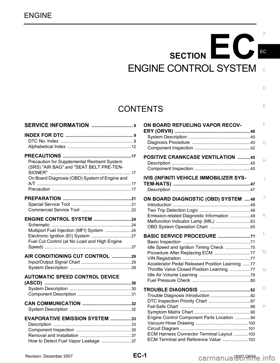
ENGINE CONTROL SYSTEM
SERVICE INFORMATION ............................9
INDEX FOR DTC .................................................9
DTC No. Index ..........................................................9
Alphabetical Index ...................................................12
PRECAUTIONS ..................................................17
Precaution for Supplemental Restraint System
(SRS) "AIR BAG" and "SEAT BELT PRE-TEN-
SIONER" .................................................................
17
On Board Diagnosis (OBD) System of Engine and
A/T ...........................................................................
17
Precaution ...............................................................17
PREPARATION ..................................................21
Special Service Tool ...............................................21
Commercial Service Tool ........................................22
ENGINE CONTROL SYSTEM ............................24
Schematic ...............................................................24
Multiport Fuel Injection (MFI) System .....................24
Electronic Ignition (EI) System ................................27
Fuel Cut Control (at No Load and High Engine
Speed) .....................................................................
27
AIR CONDITIONING CUT CONTROL ...............29
Input/Output Signal Chart ........................................29
System Description .................................................29
AUTOMATIC SPEED CONTROL DEVICE
(ASCD) ...............................................................
30
System Description .................................................30
Component Description ...........................................31
CAN COMMUNICATION ....................................32
System Description .................................................32
EVAPORATIVE EMISSION SYSTEM ................33
Description ..............................................................33
Component Inspection ............................................35
Removal and Installation .........................................37
How to Detect Fuel Vapor Leakage ........................37
ON BOARD REFUELING VAPOR RECOV-
ERY (ORVR) ......................................................
40
System Description ..................................................40
Diagnosis Procedure ...............................................40
Component Inspection .............................................42
POSITIVE CRANKCASE VENTILATION .........45
Description ...............................................................45
Component Inspection .............................................45
IVIS (INFINITI VEHICLE IMMOBILIZER SYS-
TEM-NATS) .......................................................
47
Description ...............................................................47
ON BOARD DIAGNOSTIC (OBD) SYSTEM ....48
Introduction ..............................................................48
Two Trip Detection Logic .........................................48
Emission-related Diagnostic Information .................49
Malfunction Indicator Lamp (MIL) ............................63
OBD System Operation Chart .................................65
BASIC SERVICE PROCEDURE .......................71
Basic Inspection ......................................................71
Idle Speed and Ignition Timing Check .....................75
Procedure After Replacing ECM .............................77
VIN Registration ......................................................77
Accelerator Pedal Released Position Learning .......77
Throttle Valve Closed Position Learning .................77
Idle Air Volume Learning .........................................78
Fuel Pressure Check ...............................................80
TROUBLE DIAGNOSIS ....................................82
Trouble Diagnosis Introduction ................................82
DTC Inspection Priority Chart ..................................87
Fail-Safe Chart ........................................................88
Symptom Matrix Chart .............................................90
Engine Control Component Parts Location .............94
Vacuum Hose Drawing ..........................................100
Circuit Diagram ......................................................101
ECM Harness Connector Terminal Layout ............103
ECM Terminal and Reference Value .....................103
Page 1091 of 3061
EC-8
DTC Confirmation Procedure ................................567
Wiring Diagram ......................................................569
Diagnosis Procedure .............................................570
Component Inspection ...........................................572
Removal and Installation .......................................573
DTC P2135 TP SENSOR .................................574
Component Description .........................................574
CONSULT-II Reference Value in Data Monitor
Mode ......................................................................
574
On Board Diagnosis Logic .....................................574
DTC Confirmation Procedure ................................574
Wiring Diagram ......................................................576
Diagnosis Procedure .............................................577
Component Inspection ...........................................579
Removal and Installation .......................................580
DTC P2138 APP SENSOR ..............................581
Component Description .........................................581
CONSULT-II Reference Value in Data Monitor
Mode ......................................................................
581
On Board Diagnosis Logic .....................................581
DTC Confirmation Procedure ................................582
Wiring Diagram ......................................................583
Diagnosis Procedure .............................................584
Component Inspection ...........................................587
Removal and Installation .......................................587
DTC P2A00, P2A03 A/F SENSOR 1 ...............588
Component Description .........................................588
CONSULT-II Reference Value in Data Monitor
Mode ......................................................................
588
On Board Diagnosis Logic .....................................588
DTC Confirmation Procedure ................................588
Wiring Diagram ......................................................590
Diagnosis Procedure .............................................593
Removal and Installation .......................................596
ASCD BRAKE SWITCH ..................................597
Component Description .........................................597
CONSULT-II Reference Value in Data Monitor
Mode ......................................................................
597
Wiring Diagram ......................................................598
Diagnosis Procedure .............................................599
Component Inspection ...........................................602
ASCD INDICATOR ..........................................603
Component Description .........................................603
CONSULT-II Reference Value in Data Monitor
Mode ......................................................................
603
Wiring Diagram ......................................................604
Diagnosis Procedure .............................................604
ELECTRICAL LOAD SIGNAL .........................606
Description .............................................................606
CONSULT-II Reference Value in Data Monitor
Mode ......................................................................
606
Diagnosis Procedure .............................................606
FUEL INJECTOR ..............................................608
Component Description ........................................608
CONSULT-II Reference Value in Data Monitor
Mode .....................................................................
608
Wiring Diagram .....................................................609
Diagnosis Procedure .............................................610
Component Inspection ..........................................612
Removal and Installation .......................................612
FUEL PUMP .....................................................613
Description ............................................................613
CONSULT-II Reference Value in Data Monitor
Mode .....................................................................
613
Wiring Diagram .....................................................614
Diagnosis Procedure .............................................615
Component Inspection ..........................................617
Removal and Installation .......................................618
ICC BRAKE SWITCH .......................................619
Component Description ........................................619
CONSULT-II Reference Value in Data Monitor
Mode .....................................................................
619
Wiring Diagram .....................................................620
Diagnosis Procedure .............................................621
Component Inspection ..........................................624
IGNITION SIGNAL ............................................626
Component Description ........................................626
Wiring Diagram .....................................................627
Diagnosis Procedure .............................................632
Component Inspection ..........................................635
Removal and Installation .......................................637
REFRIGERANT PRESSURE SENSOR ...........638
Component Description ........................................638
Wiring Diagram .....................................................639
Diagnosis Procedure .............................................640
Removal and Installation .......................................642
MIL AND DATA LINK CONNECTOR ...............643
Wiring Diagram .....................................................643
SERVICE DATA AND SPECIFICATIONS
(SDS) ................................................................
645
Fuel Pressure ........................................................645
Idle Speed and Ignition Timing .............................645
Calculated Load Value ..........................................645
Mass Air Flow Sensor ...........................................645
Intake Air Temperature Sensor .............................645
Engine Coolant Temperature Sensor ...................645
A/F Sensor 1 Heater .............................................645
Heated Oxygen sensor 2 Heater ..........................645
Crankshaft Position Sensor (POS) .......................646
Camshaft Position Sensor (PHASE) .....................646
Throttle Control Motor ...........................................646
Fuel Injector ..........................................................646
Fuel Pump .............................................................646