2007 INFINITI QX56 light
[x] Cancel search: lightPage 2799 of 3061
TROUBLE DIAGNOSIS
SRS-29
< SERVICE INFORMATION >
C
D
E
F
G
I
J
K
L
MA
B
SRS
N
O
P
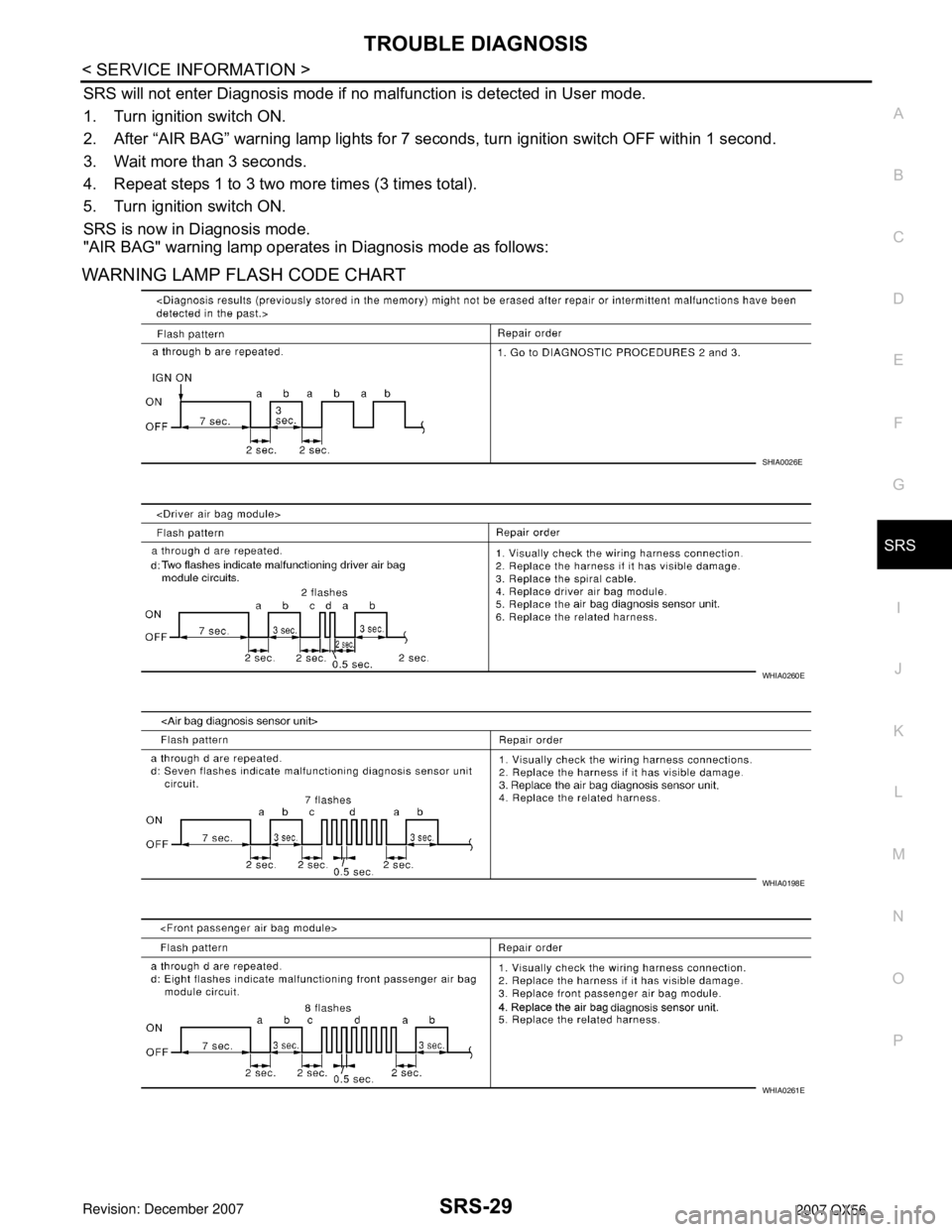
SRS will not enter Diagnosis mode if no malfunction is detected in User mode.
1. Turn ignition switch ON.
2. After “AIR BAG” warning lamp lights for 7 seconds, turn ignition switch OFF within 1 second.
3. Wait more than 3 seconds.
4. Repeat steps 1 to 3 two more times (3 times total).
5. Turn ignition switch ON.
SRS is now in Diagnosis mode.
"AIR BAG" warning lamp operates in Diagnosis mode as follows:
WARNING LAMP FLASH CODE CHART
SHIA0026E
WHIA0260E
WHIA0198E
WHIA0261E
Page 2807 of 3061
SPIRAL CABLE
SRS-37
< SERVICE INFORMATION >
C
D
E
F
G
I
J
K
L
MA
B
SRS
N
O
P
SPIRAL CABLE
Removal and InstallationINFOID:0000000003532874
REMOVAL
CAUTION:
• Before servicing the SRS, turn ignition switch OFF, disconnect both battery cables and wait at least
3 minutes.
• When servicing the SRS, do not work from directly in front of air bag module.
1. Remove the steering wheel. Refer to PS-7
.
2. Remove the column cover upper and lower.
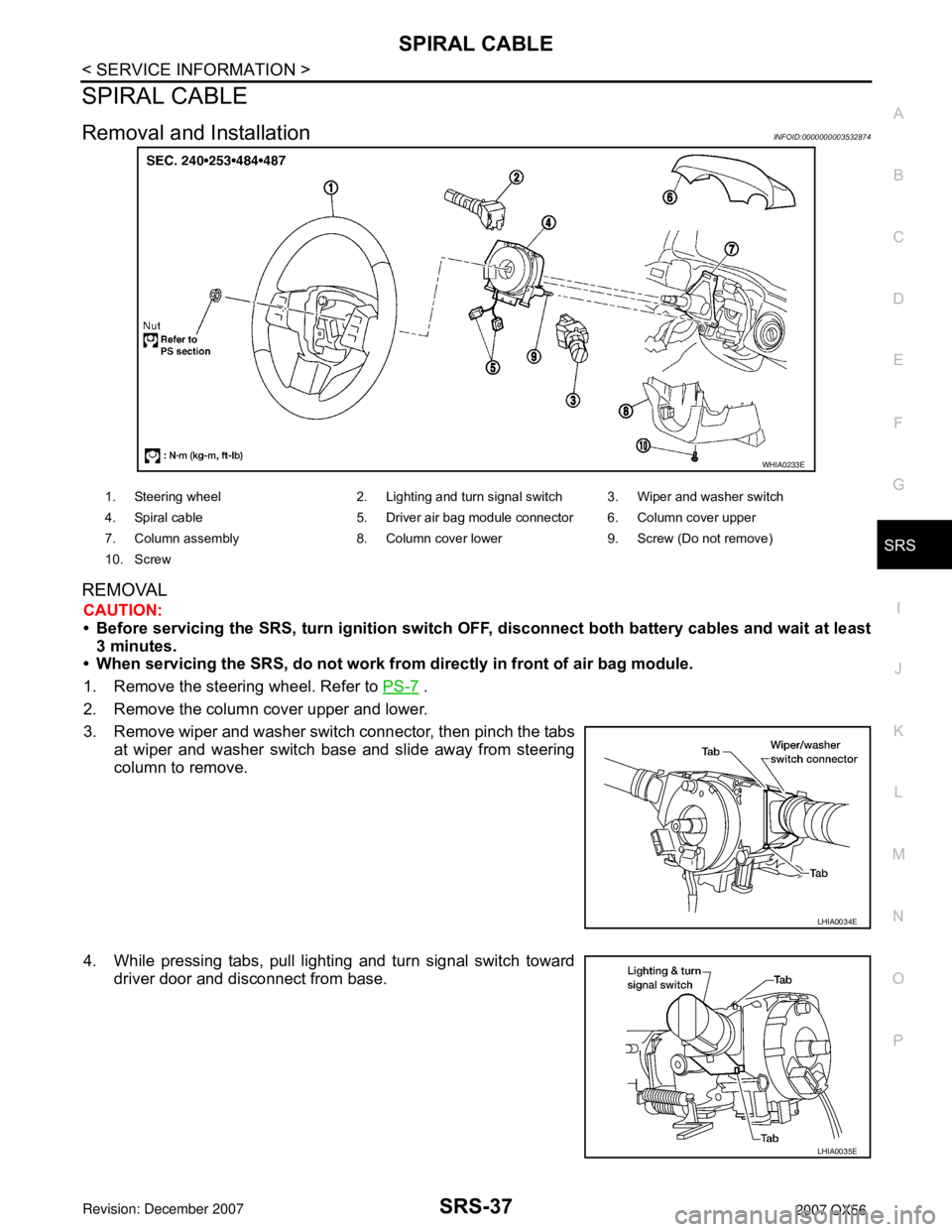
3. Remove wiper and washer switch connector, then pinch the tabs
at wiper and washer switch base and slide away from steering
column to remove.
4. While pressing tabs, pull lighting and turn signal switch toward
driver door and disconnect from base.
WHIA0233E
1. Steering wheel 2. Lighting and turn signal switch 3. Wiper and washer switch
4. Spiral cable 5. Driver air bag module connector 6. Column cover upper
7. Column assembly 8. Column cover lower 9. Screw (Do not remove)
10. Screw
LHIA0034E
LHIA0035E
Page 2856 of 3061
TF-34
< SERVICE INFORMATION >
TROUBLE DIAGNOSIS
Trouble Diagnosis Chart by Symptom
INFOID:0000000003532525
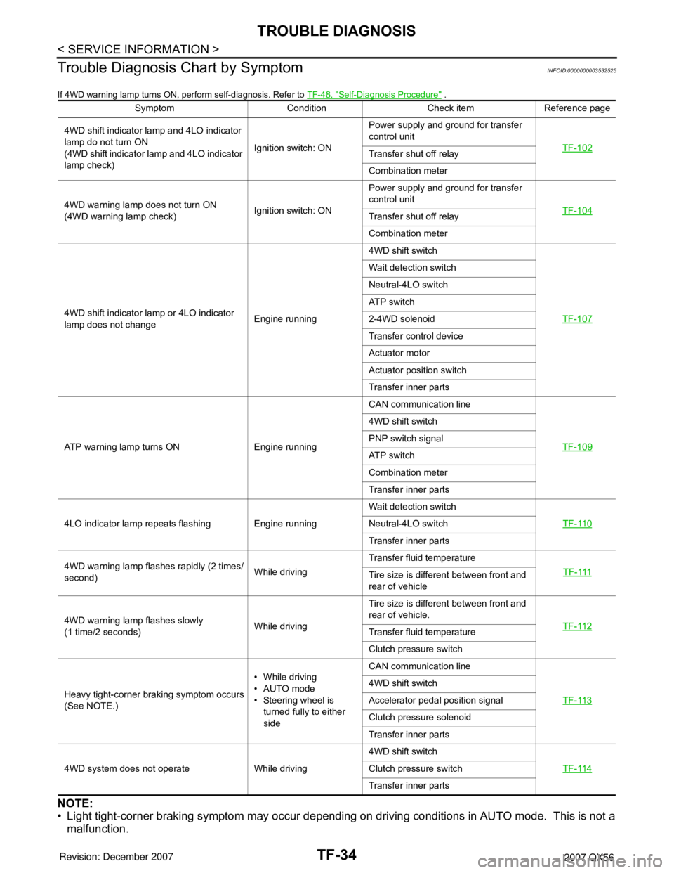
If 4WD warning lamp turns ON, perform self-diagnosis. Refer to TF-48, "Self-Diagnosis Procedure" .
NOTE:
• Light tight-corner braking symptom may occur depending on driving conditions in AUTO mode. This is not a
malfunction.
Symptom Condition Check item Reference page
4WD shift indicator lamp and 4LO indicator
lamp do not turn ON
(4WD shift indicator lamp and 4LO indicator
lamp check)Ignition switch: ONPower supply and ground for transfer
control unit
TF-102
Transfer shut off relay
Combination meter
4WD warning lamp does not turn ON
(4WD warning lamp check)Ignition switch: ONPower supply and ground for transfer
control unit
TF-104
Transfer shut off relay
Combination meter
4WD shift indicator lamp or 4LO indicator
lamp does not changeEngine running4WD shift switch
TF-107
Wait detection switch
Neutral-4LO switch
ATP switch
2-4WD solenoid
Transfer control device
Actuator motor
Actuator position switch
Transfer inner parts
ATP warning lamp turns ON Engine runningCAN communication line
TF-109
4WD shift switch
PNP switch signal
ATP switch
Combination meter
Transfer inner parts
4LO indicator lamp repeats flashing Engine runningWait detection switch
TF-110
Neutral-4LO switch
Transfer inner parts
4WD warning lamp flashes rapidly (2 times/
second)While drivingTransfer fluid temperature
TF-111
Tire size is different between front and
rear of vehicle
4WD warning lamp flashes slowly
(1 time/2 seconds)While drivingTire size is different between front and
rear of vehicle.
TF-112
Transfer fluid temperature
Clutch pressure switch
Heavy tight-corner braking symptom occurs
(See NOTE.)• While driving
•AUTO mode
• Steering wheel is
turned fully to either
sideCAN communication line
TF-113
4WD shift switch
Accelerator pedal position signal
Clutch pressure solenoid
Transfer inner parts
4WD system does not operate While driving4WD shift switch
TF-114
Clutch pressure switch
Transfer inner parts
Page 2869 of 3061
TROUBLE DIAGNOSIS
TF-47
< SERVICE INFORMATION >
C
E
F
G
H
I
J
K
L
MA
B
TF
N
O
PWORK SUPPORT
When there is no problem with transfer and 4WD system, following symptom in “AUTO” mode may be claimed
by a customer.
• Vibration when accelerating on a low µ road (snow-covered or icy road)
It is possible to deal with these symptoms by changing “CLUTCH FORCE RELEASE LIMIT VALUE”. How-
ever, be careful when changing the values because it may adversely affect driving performance.
NOTE:
A slight shock is felt at a few hertz as if it were being pushed lightly from behind.
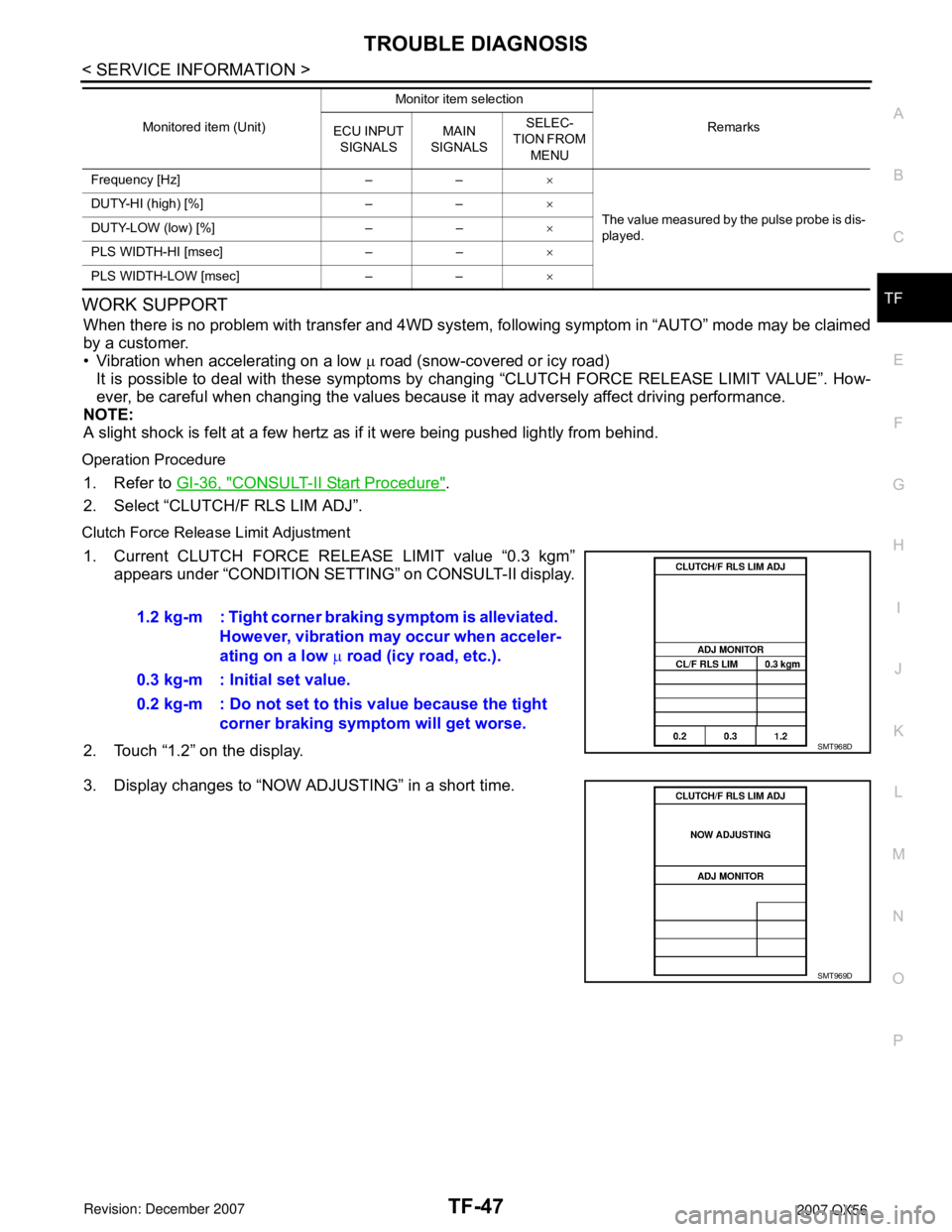
Operation Procedure
1. Refer to GI-36, "CONSULT-II Start Procedure".
2. Select “CLUTCH/F RLS LIM ADJ”.
Clutch Force Release Limit Adjustment
1. Current CLUTCH FORCE RELEASE LIMIT value “0.3 kgm”
appears under “CONDITION SETTING” on CONSULT-II display.
2. Touch “1.2” on the display.
3. Display changes to “NOW ADJUSTING” in a short time.
Frequency [Hz] – –×
The value measured by the pulse probe is dis-
played. DUTY-HI (high) [%] – –×
DUTY-LOW (low) [%] – –×
PLS WIDTH-HI [msec] – –×
PLS WIDTH-LOW [msec] – –× Monitored item (Unit)Monitor item selection
Remarks
ECU INPUT
SIGNALSMAIN
SIGNALSSELEC-
TION FROM
MENU
1.2 kg-m : Tight corner braking symptom is alleviated.
However, vibration may occur when acceler-
ating on a low µ road (icy road, etc.).
0.3 kg-m : Initial set value.
0.2 kg-m : Do not set to this value because the tight
corner braking symptom will get worse.
SMT968D
SMT969D
Page 2935 of 3061
TROUBLE DIAGNOSIS FOR SYMPTOMS
TF-113
< SERVICE INFORMATION >
C
E
F
G
H
I
J
K
L
MA
B
TF
N
O
P
NG >> GO TO 5.
5.CHECK TRANSFER CONTROL UNIT
Check transfer control unit input/output signal. Refer to TF-35, "
Transfer Control Unit Input/Output Signal Ref-
erence Value".
OK or NG
OK >> Inspection End.
NG >> Check transfer control unit pin terminals for damage or loose connection with harness connector.
If any items are damaged, repair or replace damaged parts.
Heavy Tight-corner Braking Symptom OccursINFOID:0000000003532560
SYMPTOM:
Heavy tight-corner braking symptom occurs when vehicle is driven in AUTO mode and steering wheel
is turned fully to either side.
DIAGNOSTIC PROCEDURE
NOTE:
• Light tight-corner braking symptom may occur depending on driving conditions in AUTO mode. This is not a
malfunction.
• Heavy tight-corner braking symptom occurs when vehicle is driven in the following conditions: 4WD shift
switch is "4H" or "4LO", steering wheel is turned fully to either side.
1.CHECK SYSTEM FOR CAN COMMUNICATION LINE
Perform self-diagnosis. Refer to TF-48, "
Self-Diagnosis Procedure".
Is "CAN COMM CIRCUIT [U1000]" displayed?
YES >> Perform trouble diagnosis for CAN communication line. Refer to TF-99, "CAN Communication
Line" .
NO >> GO TO 2.
2.CHECK SYSTEM FOR 4WD SHIFT SWITCH
Perform trouble diagnosis for 4WD shift switch system. Refer to TF-57, "
4WD Shift Switch".
OK or NG
OK >> GO TO 3.
NG >> Repair or replace damaged parts.
3.CHECK ACCELERATOR PEDAL POSITION SIGNAL CIRCUIT
Perform self diagnosis for ECM. Refer to E C - 111 , "
CONSULT-II Function (ENGINE)".
Is any malfunction deteced by self-diagnosis?
YES >> Check the malfunctioning system.
NO >> GO TO 4.
4.CHECK SYSTEM FOR CLUTCH PRESSURE SOLENOID
Perform trouble diagnosis for clutch pressure solenoid system. Refer toTF-92, "
Clutch Pressure Switch" .
OK or NG
OK >> GO TO 5.
NG >> Repair or replace damaged parts.
5.SYMPTOM CHECK
Check again.
OK or NG
OK >> Inspection End.
NG >> GO TO 6.
6.CHECK TRANSFER CONTROL UNIT
Check transfer control unit input/output signal. Refer to TF-35, "
Transfer Control Unit Input/Output Signal Ref-
erence Value".
OK or NG
Page 2984 of 3061
TF-162
< SERVICE INFORMATION >
TRANSFER ASSEMBLY
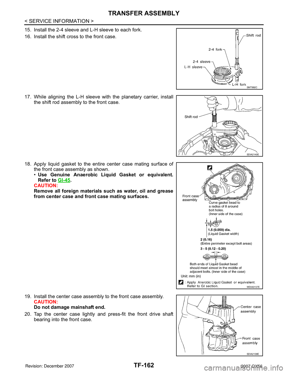
15. Install the 2-4 sleeve and L-H sleeve to each fork.
16. Install the shift cross to the front case.
17. While aligning the L-H sleeve with the planetary carrier, install
the shift rod assembly to the front case.
18. Apply liquid gasket to the entire center case mating surface of
the front case assembly as shown.
•Use Genuine Anaerobic Liquid Gasket or equivalent.
Refer to GI-45
.
CAUTION:
Remove all foreign materials such as water, oil and grease
from center case and front case mating surfaces.
19. Install the center case assembly to the front case assembly.
CAUTION:
Do not damage mainshaft end.
20. Tap the center case lightly and press-fit the front drive shaft
bearing into the front case.
SMT992C
SDIA2140E
WDIA0157E
SDIA2138E
Page 3018 of 3061
WW-1
ELECTRICAL
C
D
E
F
G
H
I
J
L
M
SECTION WW
A
B
WW
N
O
P
CONTENTS
WIPER, WASHER & HORN
SERVICE INFORMATION ............................2
PRECAUTION .....................................................2
Precaution for Supplemental Restraint System
(SRS) "AIR BAG" and "SEAT BELT PRE-TEN-
SIONER" ...................................................................
2
FRONT WIPER AND WASHER SYSTEM ..........3
Component Parts and Harness Connector Loca-
tion ............................................................................
3
System Description ...................................................3
CAN Communication System Description .................5
Schematic .................................................................6
Wiring Diagram - WIPER - ........................................7
Terminal and Reference Value for BCM ...................9
Terminal and Reference Value for IPDM E/R ...........9
Work Flow ...............................................................10
Preliminary Check ...................................................10
CONSULT-II Function (BCM) ..................................11
CONSULT-II Function (IPDM E/R) ..........................12
Front Wiper Does Not Operate ...............................13
Front Wiper Arms ....................................................21
Wiper Motor and Linkage ........................................22
Washer Nozzle Adjustment .....................................23
Washer Tube Layout ...............................................23
Wiper and Washer Switch .......................................23
Washer Fluid Reservoir ...........................................24
Washer Motor ..........................................................24
REAR WIPER AND WASHER SYSTEM ...........26
Component Parts and Harness Connector Loca-
tion ..........................................................................
26
System Description ..................................................26
Wiring Diagram - WIP/R - ........................................29
Terminal and Reference Value for BCM ..................30
How to Proceed with Trouble Diagnosis ..................30
Preliminary Check ...................................................31
CONSULT-II Function (BCM) ..................................31
Rear Wiper Does Not Operate ................................33
Rear Wiper Stop Position Is Incorrect .....................34
Only Rear Wiper Does Not Operate ........................36
Only Rear Wiper Intermittent Does Not Operate .....36
Wiper Does Not Wipe When Rear Washer Oper-
ates ..........................................................................
36
Rear Wiper Arm .......................................................37
Rear Wiper Motor ....................................................37
Rear Washer Nozzle Adjustment ............................38
Rear Washer Tube Layout ......................................39
Rear Washer Nozzle ...............................................39
Rear Wiper and Washer Switch ..............................39
Washer Fluid Reservoir ...........................................40
Washer Motor ..........................................................40
POWER SOCKET .............................................41
Wiring Diagram - P/SCKT - .....................................41
Front Power Socket LH, Rear Cargo Power Sock-
et ..............................................................................
41
Front Power Socket RH (For Cigarette Lighter),
Console Power Socket ............................................
42
HORN ................................................................43
Wiring Diagram - HORN - ........................................43
Removal and Installation .........................................43
Page 3059 of 3061
WW-42
< SERVICE INFORMATION >
POWER SOCKET
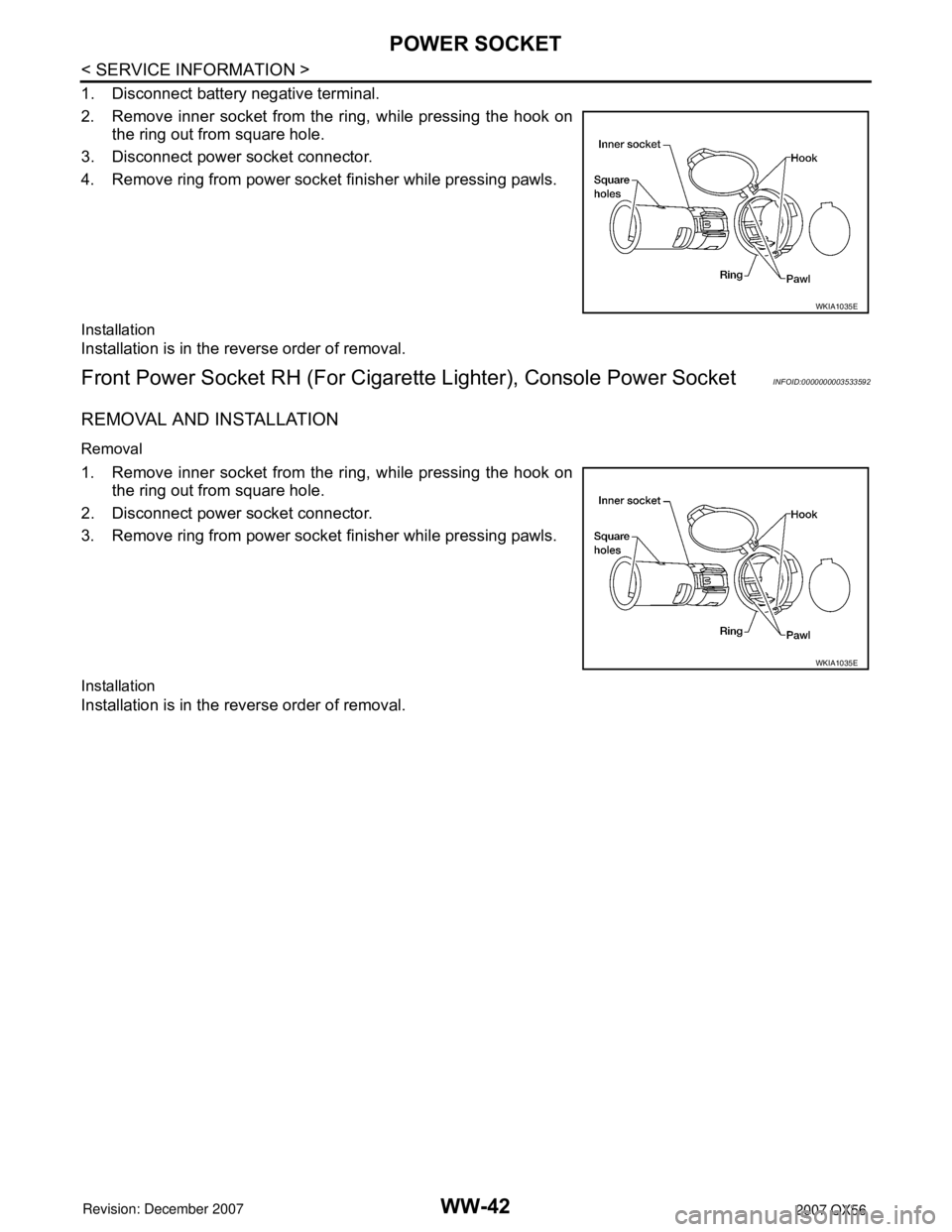
1. Disconnect battery negative terminal.
2. Remove inner socket from the ring, while pressing the hook on
the ring out from square hole.
3. Disconnect power socket connector.
4. Remove ring from power socket finisher while pressing pawls.
Installation
Installation is in the reverse order of removal.
Front Power Socket RH (For Cigarette Lighter), Console Power SocketINFOID:0000000003533592
REMOVAL AND INSTALLATION
Removal
1. Remove inner socket from the ring, while pressing the hook on
the ring out from square hole.
2. Disconnect power socket connector.
3. Remove ring from power socket finisher while pressing pawls.
Installation
Installation is in the reverse order of removal.
WKIA1035E
WKIA1035E