2007 INFINITI QX56 warning
[x] Cancel search: warningPage 2927 of 3061
TROUBLE DIAGNOSIS FOR SYMPTOMS
TF-105
< SERVICE INFORMATION >
C
E
F
G
H
I
J
K
L
MA
B
TF
N
O
P
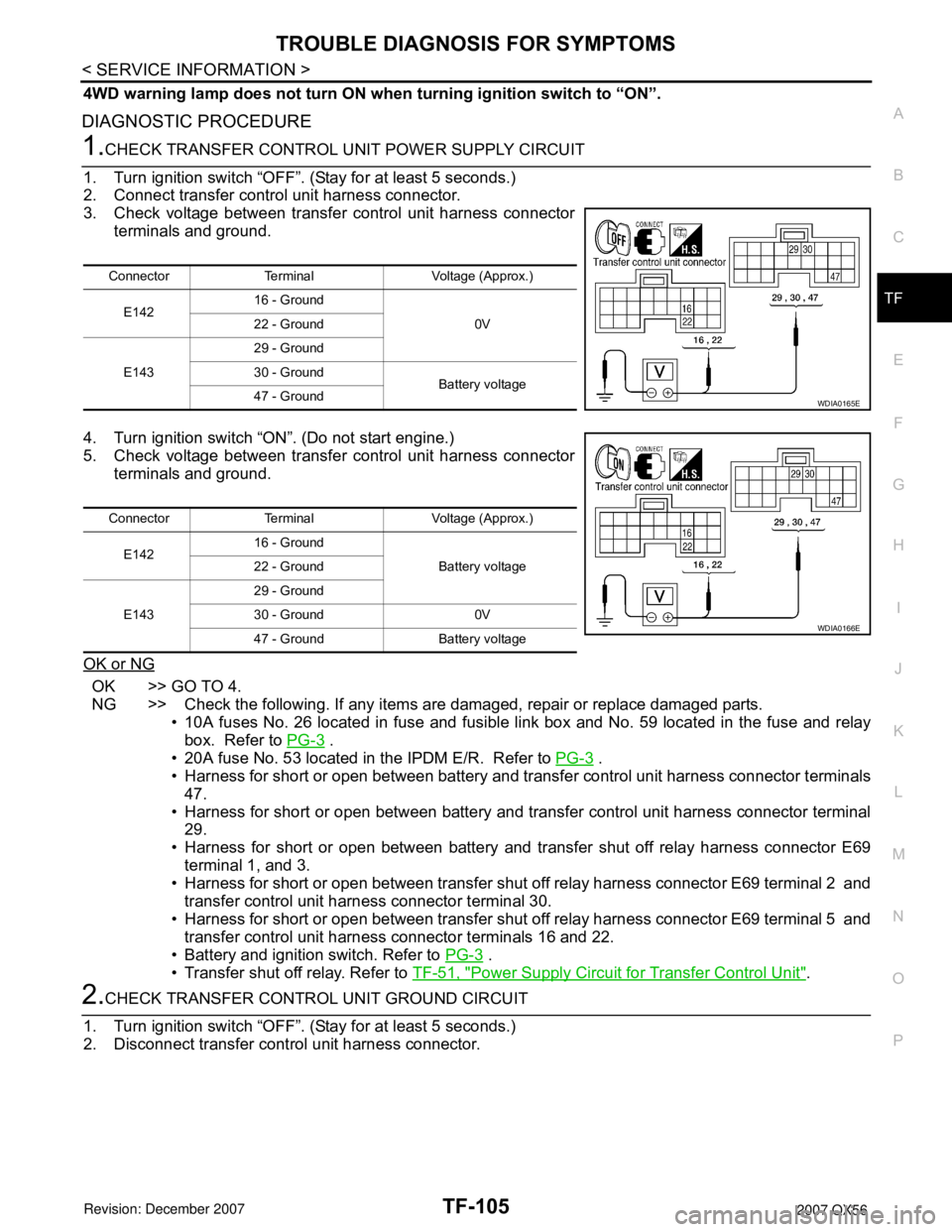
4WD warning lamp does not turn ON when turning ignition switch to “ON”.
DIAGNOSTIC PROCEDURE
1.CHECK TRANSFER CONTROL UNIT POWER SUPPLY CIRCUIT
1. Turn ignition switch “OFF”. (Stay for at least 5 seconds.)
2. Connect transfer control unit harness connector.
3. Check voltage between transfer control unit harness connector
terminals and ground.
4. Turn ignition switch “ON”. (Do not start engine.)
5. Check voltage between transfer control unit harness connector
terminals and ground.
OK or NG
OK >> GO TO 4.
NG >> Check the following. If any items are damaged, repair or replace damaged parts.
• 10A fuses No. 26 located in fuse and fusible link box and No. 59 located in the fuse and relay
box. Refer to PG-3
.
• 20A fuse No. 53 located in the IPDM E/R. Refer to PG-3
.
• Harness for short or open between battery and transfer control unit harness connector terminals
47.
• Harness for short or open between battery and transfer control unit harness connector terminal
29.
• Harness for short or open between battery and transfer shut off relay harness connector E69
terminal 1, and 3.
• Harness for short or open between transfer shut off relay harness connector E69 terminal 2 and
transfer control unit harness connector terminal 30.
• Harness for short or open between transfer shut off relay harness connector E69 terminal 5 and
transfer control unit harness connector terminals 16 and 22.
• Battery and ignition switch. Refer to PG-3
.
• Transfer shut off relay. Refer to TF-51, "
Power Supply Circuit for Transfer Control Unit".
2.CHECK TRANSFER CONTROL UNIT GROUND CIRCUIT
1. Turn ignition switch “OFF”. (Stay for at least 5 seconds.)
2. Disconnect transfer control unit harness connector.
Connector Terminal Voltage (Approx.)
E14216 - Ground
0V 22 - Ground
E14329 - Ground
30 - Ground
Battery voltage
47 - Ground
WDIA0165E
Connector Terminal Voltage (Approx.)
E14216 - Ground
Battery voltage 22 - Ground
E14329 - Ground
30 - Ground 0V
47 - Ground Battery voltage
WDIA0166E
Page 2929 of 3061
TROUBLE DIAGNOSIS FOR SYMPTOMS
TF-107
< SERVICE INFORMATION >
C
E
F
G
H
I
J
K
L
MA
B
TF
N
O
P
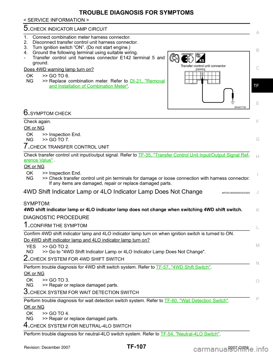
5.CHECK INDICATOR LAMP CIRCUIT
1. Connect combination meter harness connector.
2. Disconnect transfer control unit harness connector.
3. Turn ignition switch “ON”. (Do not start engine.)
4. Ground the following terminal using suitable wiring.
- Transfer control unit harness connector E142 terminal 5 and
ground.
Does 4WD warning lamp turn on?
OK >> GO TO 6.
NG >> Replace combination meter. Refer to DI-21, "
Removal
and Installation of Combination Meter".
6.SYMPTOM CHECK
Check again.
OK or NG
OK >> Inspection End.
NG >> GO TO 7.
7.CHECK TRANSFER CONTROL UNIT
Check transfer control unit input/output signal. Refer to TF-35, "
Transfer Control Unit Input/Output Signal Ref-
erence Value" .
OK or NG
OK >> Inspection End.
NG >> Check transfer control unit pin terminals for damage or loose connection with harness connector.
If any items are damaged, repair or replace damaged parts.
4WD Shift Indicator Lamp or 4LO Indicator Lamp Does Not ChangeINFOID:0000000003532555
SYMPTOM:
4WD shift indicator lamp or 4LO indicator lamp does not change when switching 4WD shift switch.
DIAGNOSTIC PROCEDURE
1.CONFIRM THE SYMPTOM
Confirm 4WD shift indicator lamp and 4LO indicator lamp turn on when ignition switch is turned to ON.
Do 4WD shift indicator lamp and 4LO indicator lamp turn on?
YES >> GO TO 2.
NO >> Go to "4WD Shift Indicator Lamp or 4LO Indicator Lamp Does Not Change".
2.CHECK SYSTEM FOR 4WD SHIFT SWITCH
Perform trouble diagnosis for 4WD shift switch system. Refer to TF-57, "
4WD Shift Switch".
OK or NG
OK >> GO TO 3.
NG >> Repair or replace damaged parts.
3.CHECK SYSTEM FOR WAIT DETECTION SWITCH
Perform trouble diagnosis for wait detection switch system. Refer to TF-60, "
Wait Detection Switch".
OK or NG
OK >> GO TO 4.
NG >> Repair or replace damaged parts.
4.CHECK SYSTEM FOR NEUTRAL-4LO SWITCH
Perform trouble diagnosis for neutral-4LO switch system. Refer to TF-54, "
Neutral-4LO Switch".
SDIA2774E
Page 2931 of 3061
TROUBLE DIAGNOSIS FOR SYMPTOMS
TF-109
< SERVICE INFORMATION >
C
E
F
G
H
I
J
K
L
MA
B
TF
N
O
P
ATP Warning Lamp Turns ONINFOID:0000000003532556
SYMPTOM:
ATP warning lamp turns ON when 4WD shift switch from “4H” to “4LO” or “4LO” to “4H” with A/T
selector lever “N” to “P” position.
DIAGNOSTIC PROCEDURE
1.CHECK SYSTEM FOR CAN COMMUNICATION LINE
Perform self-diagnosis. Refer to TF-48, "
Self-Diagnosis Procedure".
Do the self-diagnostic results indicate CAN communication?
YES >> Perform trouble diagnosis for CAN communication line. Refer to TF-99, "CAN Communication
Line".
NO >> GO TO 2.
2.CHECK SYSTEM FOR 4WD SHIFT SWITCH
Perform trouble diagnosis for 4WD shift switch system. Refer to TF-57, "
4WD Shift Switch".
OK or NG
OK >> GO TO 3.
NG >> Repair or replace damaged parts.
3.CHECK SYSTEM FOR PNP SWITCH SIGNAL
Perform trouble diagnosis for PNP switch signal system. Refer to TF-63, "
PNP Switch Signal (TCM)".
OK or NG
OK >> GO TO 4.
NG >> Repair or replace damaged parts.
4.CHECK SYSTEM FOR ATP SWITCH
Perform trouble diagnosis for ATP switch system. Refer to TF-99, "
ATP Switch".
OK or NG
OK >> GO TO 5.
NG >> Repair or replace damaged parts.
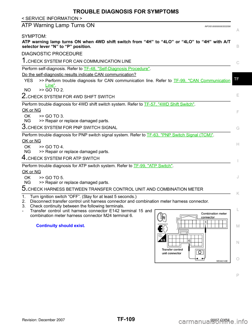
5.CHECK HARNESS BETWEEN TRANSFER CONTROL UNIT AND COMBINATION METER
1. Turn ignition switch “OFF”. (Stay for at least 5 seconds.)
2. Disconnect transfer control unit harness connector and combination meter harness connector.
3. Check continuity between the following terminals.
- Transfer control unit harness connector E142 terminal 15 and
combination meter harness connector M24 terminal 6.
Continuity should exist.
WDIA0149E
Page 2932 of 3061
TF-110
< SERVICE INFORMATION >
TROUBLE DIAGNOSIS FOR SYMPTOMS
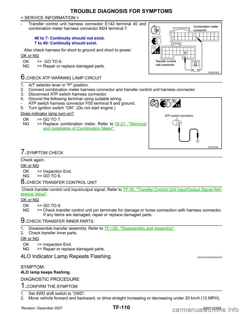
- Transfer control unit harness connector E142 terminal 40 and
combination meter harness connector M24 terminal 7.
Also check harness for short to ground and short to power.
OK or NG
OK >> GO TO 6.
NG >> Repair or replace damaged parts.
6.CHECK ATP WARNING LAMP CIRCUIT
1. A/T selector lever in "P" position.
2. Connect combination meter harness connector and transfer control unit harness connector.
3. Disconnect ATP switch harness connector.
4. Ground the following terminal using suitable wiring.
- ATP switch harness connector F55 terminal 8 and ground.
5. Turn ignition switch “ON”. (Do not start engine.)
Does indicator lamp turn on?
OK >> GO TO 7.
NG >> Replace combination meter. Refer to DI-21, "
Removal
and Installation of Combination Meter".
7.SYMPTOM CHECK
Check again.
OK or NG
OK >> Inspection End.
NG >> GO TO 8.
8.CHECK TRANSFER CONTROL UNIT
Check transfer control unit input/output signal. Refer to TF-35, "
Transfer Control Unit Input/Output Signal Ref-
erence Value".
OK or NG
OK >> GO TO 9.
NG >> Check transfer control unit pin terminals for damage or loose connection with harness connector.
If any items are damaged, repair or replace damaged parts.
9.CHECK TRANSFER INNER PARTS
1. Disassemble transfer assembly. Refer to TF-128, "
Disassembly and Assembly".
2. Check transfer inner parts.
OK or NG
OK >> Inspection End.
NG >> Repair or replace damaged parts.
4LO Indicator Lamp Repeats FlashingINFOID:0000000003532557
SYMPTOM:
4LO lamp keeps flashing.
DIAGNOSTIC PROCEDURE
1.CONFIRM THE SYMPTOM
1. Set 4WD shift switch to “2WD”.
2. Move vehicle forward and backward, or drive straight increasing or decreasing under 20 km/h (12 MPH). 40 to 7: Continuity should not exist.
7 to 40: Continuity should exist.
WDIA0150E
SDIA2769E
Page 2933 of 3061
TROUBLE DIAGNOSIS FOR SYMPTOMS
TF-111
< SERVICE INFORMATION >
C
E
F
G
H
I
J
K
L
MA
B
TF
N
O
P
Dose 4WD shift indicator lamp keep flashing?
YES >> GO TO 2.
NO >> Inspection End.
2.CHECK SYSTEM FOR WAIT DETECTION SWITCH
Perform trouble diagnosis for wait detection switch system. Refer to TF-60, "
Wait Detection Switch".
OK or NG
OK >> GO TO 3.
NG >> Repair or replace damaged parts.
3.CHECK SYSTEM FOR NEUTRAL-4LO SWITCH
Perform trouble diagnosis for neutral-4LO switch system. Refer to TF-54, "
Neutral-4LO Switch".
OK or NG
OK >> GO TO 4.
NG >> Repair or replace damaged parts.
4.SYMPTOM CHECK
Check again.
OK or NG
OK >> Inspection End.
NG >> GO TO 5.
5.CHECK TRANSFER CONTROL UNIT
Check transfer control unit input/output signal. Refer to TF-35, "
Transfer Control Unit Input/Output Signal Ref-
erence Value".
OK or NG
OK >> GO TO 6.
NG >> Check transfer control unit pin terminals for damage or loose connection with harness connector.
If any items are damaged, repair or replace damaged parts.
6.CHECK TRANSFER INNER PARTS
1. Disassemble transfer assembly. Refer to TF-128, "
Disassembly and Assembly".
2. Check transfer inner parts.
OK or NG
OK >> Inspection End.
NG >> Repair or replace damaged parts.
4WD Warning Lamp Flashes RapidlyINFOID:0000000003532558
SYMPTOM:
While driving, 4WD warning lamp flashes rapidly.
NOTE:
Rapid flashing: 2 times/second
DIAGNOSTIC PROCEDURE
1.CHECK TIRE
Check the following.
• Tire pressure
• Wear condition
• Longitudinal tire size (There is no difference between longitudinal tires.)
OK or NG
OK >> GO TO 2.
NG >> Repair or replace damaged parts.
2.CHECK 4WD WARNING LAMP
Stop the vehicle and allow it to idle for a short period of time.
Does flashing stop?
Page 2934 of 3061
TF-112
< SERVICE INFORMATION >
TROUBLE DIAGNOSIS FOR SYMPTOMS
YES >> Inspection End.
NO >> GO TO 3.
3.CHECK TRANSFER FLUID TEMPERATURE
Perform trouble diagnosis for transfer fluid temperature system. Refer to TF-90, "
Transfer Fluid Temperature".
OK or NG
OK >> GO TO 4.
NG >> Repair or replace damaged parts.
4.SYMPTOM CHECK
Check again.
OK or NG
OK >> Inspection End.
NG >> GO TO 5.
5.CHECK TRANSFER CONTROL UNIT
Check transfer control unit input/output signal. Refer to TF-35, "
Transfer Control Unit Input/Output Signal Ref-
erence Value".
OK or NG
OK >> Inspection End.
NG >> Check transfer control unit pin terminals for damage or loose connection with harness connector.
If any items are damaged, repair or replace damaged parts.
4WD Warning Lamp Flashes SlowlyINFOID:0000000003532559
SYMPTOM:
While driving, 4WD warning lamp flashes slowly. (When continuing to flash until turning ignition
switch OFF.)
NOTE:
Slow flashing: 1 time/2 seconds
DIAGNOSTIC PROCEDURE
1.CHECK TIRE
Check the following.
• Tire pressure
• Wear condition
• Longitudinal tire size (There is no difference between longitudinal tires.)
OK or NG
OK >> GO TO 2.
NG >> Repair or replace damaged parts.
2.CHECK TRANSFER FLUID TEMPERATURE
Perform trouble diagnosis for transfer fluid temperature system. Refer to TF-90, "
Transfer Fluid Temperature".
OK or NG
OK >> GO TO 3.
NG >> Repair or replace damaged parts.
3.CHECK CLUTCH PRESSURE SWITCH
Perform trouble diagnosis for clutch pressure switch system. Refer to TF-92, "
Clutch Pressure Switch".
OK or NG
OK >> GO TO 4.
NG >> Repair or replace damaged parts.
4.SYMPTOM CHECK
Check again.
OK or NG
OK >> Inspection End.
Page 2950 of 3061
TF-128
< SERVICE INFORMATION >
TRANSFER ASSEMBLY
TRANSFER ASSEMBLY
Removal and InstallationINFOID:0000000003532570
REMOVAL
1. Remove the drain plug and gasket. Drain the fluid. Refer to TF-11, "Replacement".
2. Remove the A/T undercover using power tool.
3. Remove the center exhaust tube and main muffler. Refer to EX-3, "
Removal and Installation".
4. Remove the front and rear propeller shafts. Refer to PR-4, "
Removal and Installation" (front), PR-8,
"Removal and Installation" (rear).
CAUTION:
Do not damage spline, sleeve yoke and rear oil seal when removing rear propeller shaft.
NOTE:
Insert a plug into the rear oil seal after removing the rear propeller shaft.
5. Remove the A/T nuts from the A/T crossmember.
6. Position two suitable jacks under the A/T and transfer assembly.
7. Remove the crossmember. Refer to AT-223, "
Removal and Installation (2WD)".
WARNING:
Support A/T and transfer assembly using two suitable jacks while removing crossmember.
8. Disconnect the electrical connectors from the following:
•ATP switch
• Neutral 4LO switch
• Wait detection switch
• Transfer motor
• Transfer control device
• Transfer terminal cord assembly
9. Disconnect each air breather hose from the following. Refer to TF-122, "
Removal and Installation".
• Actuator
• Breather tube (transfer)
• Transfer motor (case connector)
10. Remove the transfer control device from the extension housing.
11. Remove the transfer to A/T and A/T to transfer bolts.
WARNING:
Support transfer assembly with suitable jack while removing it.
12. Remove the transfer assembly.
INSTALLATION
Installation is in the reverse order of removal.
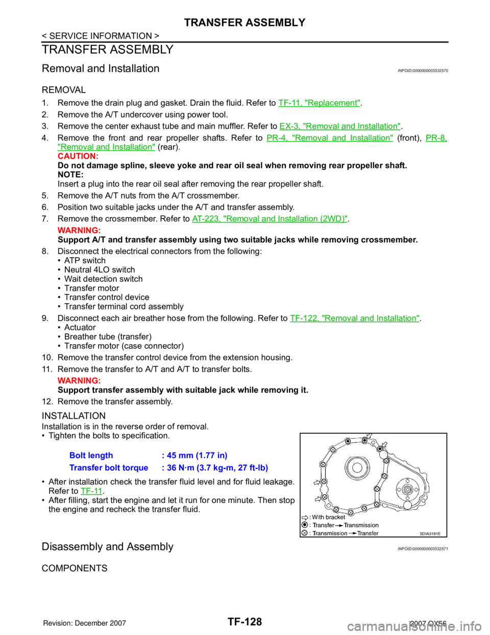
• Tighten the bolts to specification.
• After installation check the transfer fluid level and for fluid leakage.
Refer to TF-11
.
• After filling, start the engine and let it run for one minute. Then stop
the engine and recheck the transfer fluid.
Disassembly and AssemblyINFOID:0000000003532571
COMPONENTS
Bolt length : 45 mm (1.77 in)
Transfer bolt torque : 36 N·m (3.7 kg-m, 27 ft-lb)
SDIA3181E
Page 2990 of 3061

WT-1
SUSPENSION
C
D
F
G
H
I
J
K
L
M
SECTION WT
A
B
WT
N
O
PCONTENTS
ROAD WHEELS & TIRES
SERVICE INFORMATION ............................2
PRECAUTIONS ...................................................2
Precaution for Supplemental Restraint System
(SRS) "AIR BAG" and "SEAT BELT PRE-TEN-
SIONER" ...................................................................
2
PREPARATION ...................................................3
Special Service Tool .................................................3
Commercial Service Tool ..........................................3
NOISE, VIBRATION AND HARSHNESS
(NVH) TROUBLESHOOTING .............................
4
NVH Troubleshooting Chart ......................................4
WHEEL ................................................................5
Inspection ..................................................................5
WHEEL AND TIRE ASSEMBLY .........................6
Balancing Wheels .....................................................6
Rotation .....................................................................7
LOW TIRE PRESSURE WARNING SYSTEM .....8
System Component ...................................................8
System Description ...................................................8
CAN COMMUNICATION ....................................10
System Description .................................................10
TROUBLE DIAGNOSIS .....................................11
Wiring Diagram- T/WARN - .....................................11
Terminal and Reference Value (BCM) ....................12
ID Registration Procedure .......................................12
Transmitter Wake Up Operation .............................14
CONSULT-II Function (BCM) ..................................15
Self-Diagnosis .........................................................15
How to Perform Trouble Diagnosis for Quick and
Accurate Repair .......................................................
17
Preliminary Check ...................................................18
Flash Code/Symptom Chart ....................................18
TROUBLE DIAGNOSIS FOR SELF-DIAG-
NOSTIC ITEMS .................................................
20
Data from Transmitter Not Being Received .............20
Transmitter Malfunction ...........................................20
Transmitter Pressure Malfunction ............................21
Vehicle Speed Signal ..............................................21
Ignition Signal ..........................................................22
TROUBLE DIAGNOSIS FOR SYMPTOMS ......23
Low Tire Pressure Warning Lamp Does Not Come
On When Ignition Switch Is Turned On ...................
23
Low Tire Pressure Warning Lamp Stays On When
Ignition Switch Is Turned On ...................................
23
Low Tire Pressure Warning Lamp Flashes When
Ignition Switch Is Turned On ...................................
24
Hazard Warning Lamps Flash When Ignition
Switch Is Turned On ................................................
25
"TIRE PRESSURE" Information in Display Unit
Does Not Exist .........................................................
25
ID Registration Cannot Be Completed ....................25
REMOVAL AND INSTALLATION .....................26
Transmitter (Pressure Sensor) ................................26
SERVICE DATA AND SPECIFICATIONS
(SDS) .................................................................
28
Road Wheel .............................................................28
Tire ..........................................................................28