Page 2271 of 3061

LT-64
< SERVICE INFORMATION >
TURN SIGNAL AND HAZARD WARNING LAMPS
3. Perform preliminary check. Refer to LT-64, "Preliminary Check" .
4. Check symptom and repair or replace the component.
5. Do turn signal and hazard warning lamps operate normally? If YES: GO TO 6. If NO: GO TO 4.
6. Inspection End.
Preliminary CheckINFOID:0000000003533410
CHECK POWER SUPPLY AND GROUND CIRCUIT FOR BCM
Refer to BCS-15, "BCM Power Supply and Ground Circuit Inspection".
CONSULT-II Function (BCM)INFOID:0000000003533411
Refer to BCS-16, "CONSULT-II Function (BCM)".
CONSULT-II START PROCEDURE
Refer to GI-36, "CONSULT-II Start Procedure".
DATA MONITOR
Display Item List
ACTIVE TEST
Display Item List
Front Turn Signal Lamp Does Not OperateINFOID:0000000003533412
1.CHECK COMBINATION SWITCH INPUT SIGNAL
With CONSULT-II
Select "BCM" on CONSULT-II. With "FLASHER" data monitor, make
sure "TURN SIGNAL R" and "TURN SIGNAL L" turns ON-OFF
linked with operation of lighting switch.
Without CONSULT-II
Refer to LT-73, "
Combination Switch Inspection" .
OK or NG
OK >> GO TO 2.
NG >> Check lighting switch. Refer to LT-73, "
Combination Switch Inspection".
2.ACTIVE TEST
With CONSULT-II
Monitor item Contents
IGN ON SW "ON/OFF" Displays "IGN position (ON)/OFF, ACC position (OFF)" judged from the ignition switch signal.
HAZARD SW "ON/OFF" Displays "Hazard ON (ON)/Hazard OFF (OFF)" status, determined from hazard switch signal.
TURN SIGNAL R "ON/OFF" Displays "Turn right (ON)/Other (OFF)" status, determined from lighting switch signal.
TURN SIGNAL L "ON/OFF" Displays "Turn left (ON)/Other (OFF)" status, determined from lighting switch signal.
BRAKE SW "ON/OFF" Displays status of stop lamp switch.
Test item Description
FLASHER (RH) Turn signal lamp (right) can be operated by any ON-OFF operations.
FLASHER (LH) Turn signal lamp (left) can be operated by any ON-OFF operations.
When lighting switch is in
TURN RH position: TURN SIGNAL R ON
When lighting switch is in
TURN LH position: TURN SIGNAL L ON
SKIA4499E
Page 2272 of 3061

TURN SIGNAL AND HAZARD WARNING LAMPS
LT-65
< SERVICE INFORMATION >
C
D
E
F
G
H
I
J
L
MA
B
LT
N
O
P
1. Select "FLASHER" during active test. Refer to LT-64, "CON-
SULT-II Function (BCM)" .
2. Make sure "FLASHER RH" and "FLASHER LH" operate.
Without CONSULT-II
GO TO 3.
OK or NG
OK >> Replace BCM. Refer to BCS-24, "BCM".
NG >> GO TO 3.
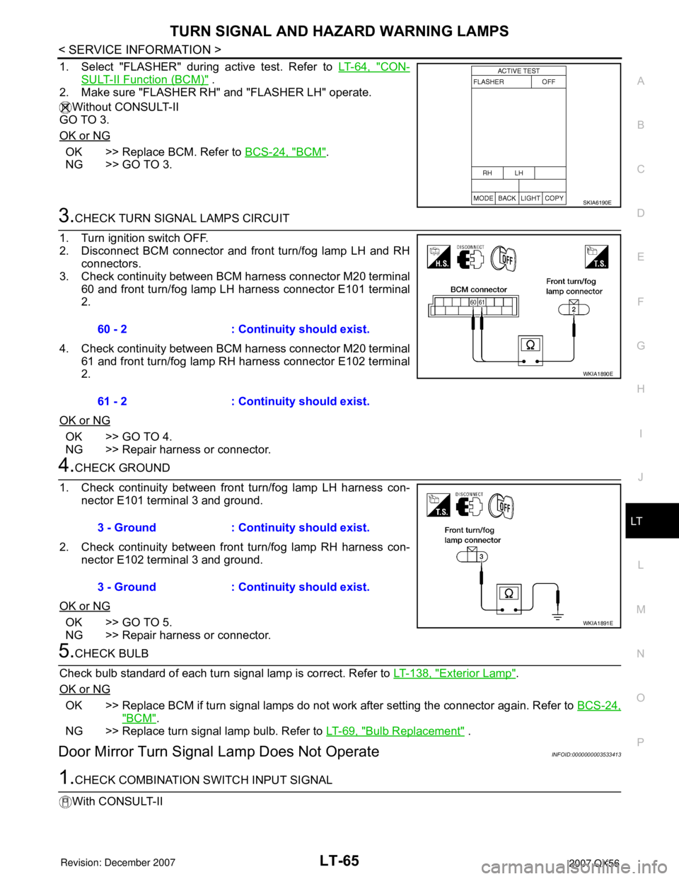
3.CHECK TURN SIGNAL LAMPS CIRCUIT
1. Turn ignition switch OFF.
2. Disconnect BCM connector and front turn/fog lamp LH and RH
connectors.
3. Check continuity between BCM harness connector M20 terminal
60 and front turn/fog lamp LH harness connector E101 terminal
2.
4. Check continuity between BCM harness connector M20 terminal
61 and front turn/fog lamp RH harness connector E102 terminal
2.
OK or NG
OK >> GO TO 4.
NG >> Repair harness or connector.
4.CHECK GROUND
1. Check continuity between front turn/fog lamp LH harness con-
nector E101 terminal 3 and ground.
2. Check continuity between front turn/fog lamp RH harness con-
nector E102 terminal 3 and ground.
OK or NG
OK >> GO TO 5.
NG >> Repair harness or connector.
5.CHECK BULB
Check bulb standard of each turn signal lamp is correct. Refer to LT-138, "
Exterior Lamp".
OK or NG
OK >> Replace BCM if turn signal lamps do not work after setting the connector again. Refer to BCS-24,
"BCM".
NG >> Replace turn signal lamp bulb. Refer to LT-69, "
Bulb Replacement" .
Door Mirror Turn Signal Lamp Does Not OperateINFOID:0000000003533413
1.CHECK COMBINATION SWITCH INPUT SIGNAL
With CONSULT-II
SKIA6190E
60 - 2 : Continuity should exist.
61 - 2 : Continuity should exist.
WKIA1890E
3 - Ground : Continuity should exist.
3 - Ground : Continuity should exist.
WKIA1891E
Page 2273 of 3061

LT-66
< SERVICE INFORMATION >
TURN SIGNAL AND HAZARD WARNING LAMPS
Select "BCM" on CONSULT-II. With "FLASHER" data monitor, make
sure "TURN SIGNAL R" and "TURN SIGNAL L" turns ON-OFF
linked with operation of lighting switch.
Without CONSULT-II
Refer to LT-73, "
Combination Switch Inspection".
OK or NG
OK >> GO TO 2.
NG >> Check lighting switch. Refer to LT-73, "
Combination Switch Inspection".
2.ACTIVE TEST
With CONSULT-II
1. Select "FLASHER" during active test. Refer to LT-64, "
CON-
SULT-II Function (BCM)".
2. Make sure "FLASHER RH" and "FLASHER LH" operate.
Without CONSULT-II
GO TO 3.
OK or NG
OK >> Replace BCM. Refer to BCS-24, "BCM".
NG >> GO TO 3.
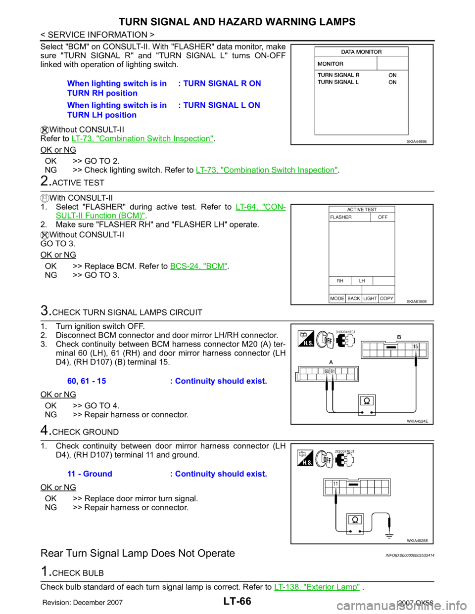
3.CHECK TURN SIGNAL LAMPS CIRCUIT
1. Turn ignition switch OFF.
2. Disconnect BCM connector and door mirror LH/RH connector.
3. Check continuity between BCM harness connector M20 (A) ter-
minal 60 (LH), 61 (RH) and door mirror harness connector (LH
D4), (RH D107) (B) terminal 15.
OK or NG
OK >> GO TO 4.
NG >> Repair harness or connector.
4.CHECK GROUND
1. Check continuity between door mirror harness connector (LH
D4), (RH D107) terminal 11 and ground.
OK or NG
OK >> Replace door mirror turn signal.
NG >> Repair harness or connector.
Rear Turn Signal Lamp Does Not OperateINFOID:0000000003533414
1.CHECK BULB
Check bulb standard of each turn signal lamp is correct. Refer to LT-138, "
Exterior Lamp" . When lighting switch is in
TURN RH position: TURN SIGNAL R ON
When lighting switch is in
TURN LH position: TURN SIGNAL L ON
SKIA4499E
SKIA6190E
60, 61 - 15 : Continuity should exist.
WKIA4524E
11 - Ground : Continuity should exist.
WKIA4525E
Page 2274 of 3061

TURN SIGNAL AND HAZARD WARNING LAMPS
LT-67
< SERVICE INFORMATION >
C
D
E
F
G
H
I
J
L
MA
B
LT
N
O
P
OK or NG
OK >> GO TO 2.
NG >> Replace turn signal lamp bulb. Refer to LT-69, "
Bulb Replacement" .
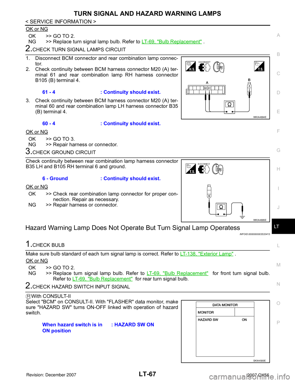
2.CHECK TURN SIGNAL LAMPS CIRCUIT
1. Disconnect BCM connector and rear combination lamp connec-
tor.
2. Check continuity between BCM harness connector M20 (A) ter-
minal 61 and rear combination lamp RH harness connector
B105 (B) terminal 4.
3. Check continuity between BCM harness connector M20 (A) ter-
minal 60 and rear combination lamp LH harness connector B35
(B) terminal 4.
OK or NG
OK >> GO TO 3.
NG >> Repair harness or connector.
3.CHECK GROUND CIRCUIT
Check continuity between rear combination lamp harness connector
B35 LH and B105 RH terminal 6 and ground.
OK or NG
OK >> Check rear combination lamp connector for proper con-
nection. Repair as necessary.
NG >> Repair harness or connector.
Hazard Warning Lamp Does Not Operate But Turn Signal Lamp Operatess
INFOID:0000000003533415
1.CHECK BULB
Make sure bulb standard of each turn signal lamp is correct. Refer to LT-138, "
Exterior Lamp" .
OK or NG
OK >> GO TO 2.
NG >> Replace turn signal lamp bulb. Refer to LT-69, "
Bulb Replacement" for front turn signal bulb.
Refer to LT-69, "
Bulb Replacement" for rear turn signal bulb.
2.CHECK HAZARD SWITCH INPUT SIGNAL
With CONSULT-II
Select "BCM" on CONSULT-II. With "FLASHER" data monitor, make
sure "HAZARD SW" turns ON-OFF linked with operation of hazard
switch.61 - 4 : Continuity should exist.
60 - 4 : Continuity should exist.
WKIA4694E
6 - Ground : Continuity should exist.
WKIA4695E
When hazard switch is in
ON position : HAZARD SW ON
SKIA4500E
Page 2275 of 3061

LT-68
< SERVICE INFORMATION >
TURN SIGNAL AND HAZARD WARNING LAMPS
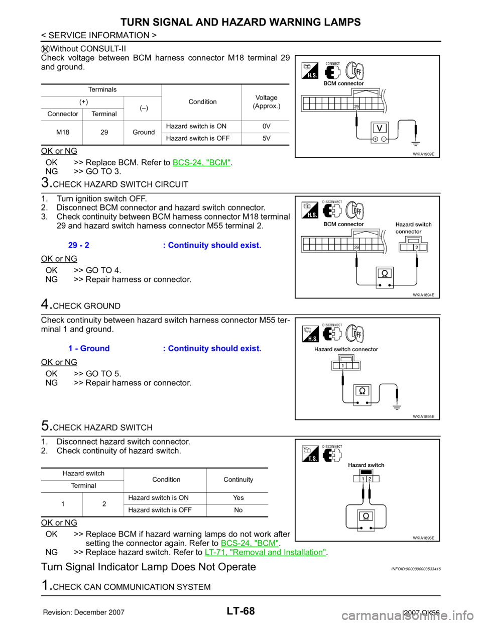
Without CONSULT-II
Check voltage between BCM harness connector M18 terminal 29
and ground.
OK or NG
OK >> Replace BCM. Refer to BCS-24, "BCM".
NG >> GO TO 3.
3.CHECK HAZARD SWITCH CIRCUIT
1. Turn ignition switch OFF.
2. Disconnect BCM connector and hazard switch connector.
3. Check continuity between BCM harness connector M18 terminal
29 and hazard switch harness connector M55 terminal 2.
OK or NG
OK >> GO TO 4.
NG >> Repair harness or connector.
4.CHECK GROUND
Check continuity between hazard switch harness connector M55 ter-
minal 1 and ground.
OK or NG
OK >> GO TO 5.
NG >> Repair harness or connector.
5.CHECK HAZARD SWITCH
1. Disconnect hazard switch connector.
2. Check continuity of hazard switch.
OK or NG
OK >> Replace BCM if hazard warning lamps do not work after
setting the connector again. Refer to BCS-24, "
BCM".
NG >> Replace hazard switch. Refer to LT-71, "
Removal and Installation".
Turn Signal Indicator Lamp Does Not OperateINFOID:0000000003533416
1.CHECK CAN COMMUNICATION SYSTEM
Te r m i n a l s
ConditionVoltag e
(Approx.) (+)
(–)
Connector Terminal
M18 29 GroundHazard switch is ON 0V
Hazard switch is OFF 5V
WKIA1969E
29 - 2 : Continuity should exist.
WKIA1894E
1 - Ground : Continuity should exist.
WKIA1895E
Hazard switch
Condition Continuity
Te r m i n a l
12Hazard switch is ON Yes
Hazard switch is OFF No
WKIA1896E
Page 2276 of 3061
TURN SIGNAL AND HAZARD WARNING LAMPS
LT-69
< SERVICE INFORMATION >
C
D
E
F
G
H
I
J
L
MA
B
LT
N
O
P
Check CAN communication. Refer to LAN-4, "CAN Communication System".
OK or NG
OK >> Replace combination meter. Refer to DI-21, "Removal and Installation of Combination Meter" .
NG >> Repair as necessary.
Bulb ReplacementINFOID:0000000003533417
TURN SIGNAL LAMP (FRONT)
Removal
1. Remove front fog lamp. Refer to LT-56, "Removal and Installation".
2. Twist turn signal socket and remove from front fog lamp.
3. Remove turn signal bulb from socket.
Installation
Installation is in the reverse order of removal.
TURN SIGNAL LAMP (REAR)
Refer to LT-93, "Bulb Replacement".
Removal and InstallationINFOID:0000000003533418
FRONT TURN SIGNAL LAMP
Refer to LT-22, "Removal and Installation".
REAR TURN SIGNAL LAMP
Refer to LT-93, "Removal and Installation".
Page 2277 of 3061
LT-70
< SERVICE INFORMATION >
LIGHTING AND TURN SIGNAL SWITCH
LIGHTING AND TURN SIGNAL SWITCH
Removal and InstallationINFOID:0000000003533419
Removal
1. Remove steering column cover.
2. While pressing tabs, pull lighting and turn signal switch toward
driver door and disconnect from the base.
Installation
Installation is in the reverse order of removal.
LKIA0013E
Page 2278 of 3061
HAZARD SWITCH
LT-71
< SERVICE INFORMATION >
C
D
E
F
G
H
I
J
L
MA
B
LT
N
O
P
HAZARD SWITCH
Removal and InstallationINFOID:0000000003533420
Removal
1. Remove cluster lid C. Refer to IP-10.
2. Remove screws and remove the hazard switch.
Installation
Installation is in the reverse order of removal.
WKIA1897E