Page 2263 of 3061

LT-56
< SERVICE INFORMATION >
FRONT FOG LAMP
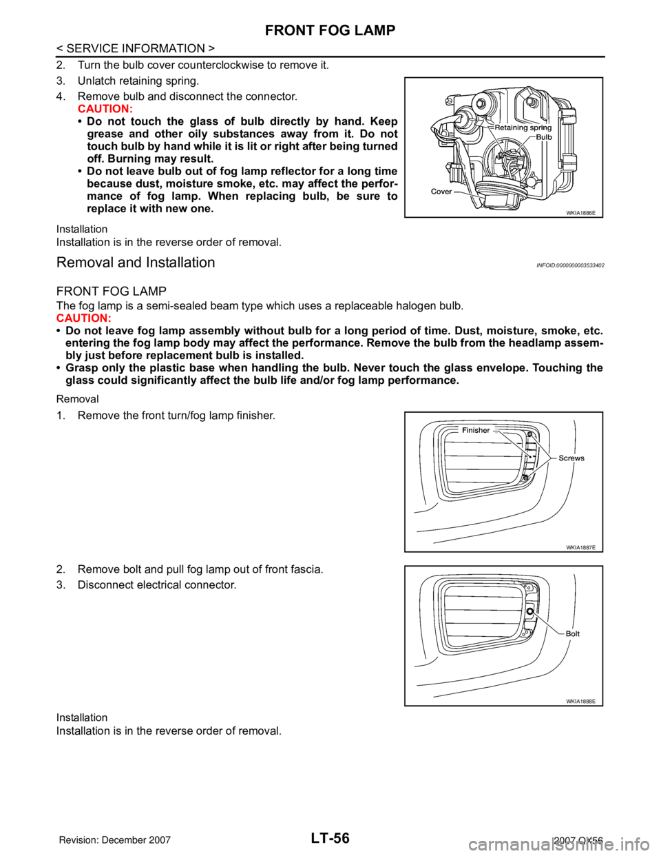
2. Turn the bulb cover counterclockwise to remove it.
3. Unlatch retaining spring.
4. Remove bulb and disconnect the connector.
CAUTION:
• Do not touch the glass of bulb directly by hand. Keep
grease and other oily substances away from it. Do not
touch bulb by hand while it is lit or right after being turned
off. Burning may result.
• Do not leave bulb out of fog lamp reflector for a long time
because dust, moisture smoke, etc. may affect the perfor-
mance of fog lamp. When replacing bulb, be sure to
replace it with new one.
Installation
Installation is in the reverse order of removal.
Removal and InstallationINFOID:0000000003533402
FRONT FOG LAMP
The fog lamp is a semi-sealed beam type which uses a replaceable halogen bulb.
CAUTION:
• Do not leave fog lamp assembly without bulb for a long period of time. Dust, moisture, smoke, etc.
entering the fog lamp body may affect the performance. Remove the bulb from the headlamp assem-
bly just before replacement bulb is installed.
• Grasp only the plastic base when handling the bulb. Never touch the glass envelope. Touching the
glass could significantly affect the bulb life and/or fog lamp performance.
Removal
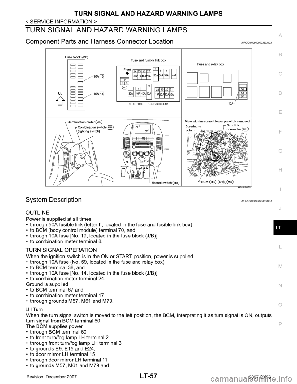
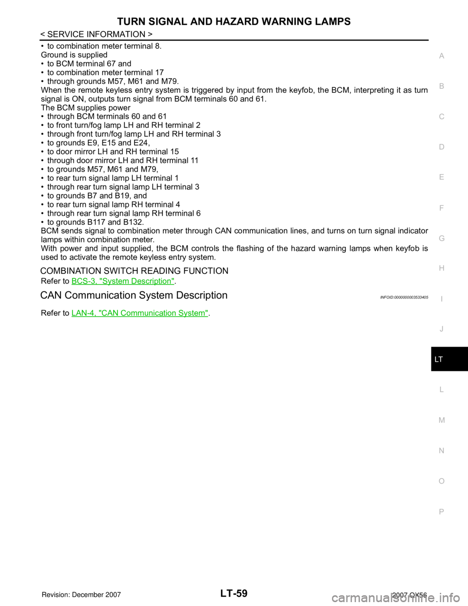
1. Remove the front turn/fog lamp finisher.
2. Remove bolt and pull fog lamp out of front fascia.
3. Disconnect electrical connector.
Installation
Installation is in the reverse order of removal.
WKIA1886E
WKIA1887E
WKIA1888E
Page 2264 of 3061

TURN SIGNAL AND HAZARD WARNING LAMPS
LT-57
< SERVICE INFORMATION >
C
D
E
F
G
H
I
J
L
MA
B
LT
N
O
P
TURN SIGNAL AND HAZARD WARNING LAMPS
Component Parts and Harness Connector LocationINFOID:0000000003533403
System DescriptionINFOID:0000000003533404
OUTLINE
Power is supplied at all times
• through 50A fusible link (letter f , located in the fuse and fusible link box)
• to BCM (body control module) terminal 70, and
• through 10A fuse [No. 19, located in the fuse block (J/B)]
• to combination meter terminal 8.
TURN SIGNAL OPERATION
When the ignition switch is in the ON or START position, power is supplied
• through 10A fuse (No. 59, located in the fuse and relay box)
• to BCM terminal 38, and
• through 10A fuse [No. 14, located in the fuse block (J/B)]
• to combination meter terminal 24.
Ground is supplied
• to BCM terminal 67 and
• to combination meter terminal 17
• through grounds M57, M61 and M79.
LH Turn
When the turn signal switch is moved to the left position, the BCM, interpreting it as turn signal is ON, outputs
turn signal from BCM terminal 60.
The BCM supplies power
• through BCM terminal 60
• to front turn/fog lamp LH terminal 2
• through front turn/fog lamp LH terminal 3
• to grounds E9, E15 and E24,
• to door mirror LH terminal 15
• through door mirror LH terminal 11
• to grounds M57, M61 and M79 and
WKIA3554E
Page 2265 of 3061

LT-58
< SERVICE INFORMATION >
TURN SIGNAL AND HAZARD WARNING LAMPS
• to rear combination lamp LH terminal 4
• through rear combination signal lamp LH terminal 6
• to grounds B7 and B19.
BCM sends signal to combination meter through CAN communication lines, and turns on turn signal indicator
lamp within combination meter.
RH Turn
When the turn signal switch is moved to the right position, the BCM, interpreting it as turn signal is ON, outputs
turn signal from BCM terminal 61.
The BCM supplies power
• through BCM terminal 61
• to front turn/fog lamp RH terminal 2
• through front turn/fog lamp RH terminal 3
• to grounds E9, E15 and E24,
• to door mirror RH terminal 15
• through door mirror RH terminal 11
• to grounds M57, M61 and M79 and
• to rear combination lamp RH terminal 4
• through rear combination lamp terminal 6
• to grounds B117 and B132.
BCM sends signal to combination meter through CAN communication lines, and turns on turn signal indicator
lamp within combination meter.
HAZARD LAMP OPERATION
Power is supplied at all times
• through 50A fusible link (letter f , located in the fuse and fusible link box)
• to BCM terminal 70, and
• through 10A fuse [No. 19, located in the fuse block (J/B)]
• to combination meter terminal 8.
Ground is supplied
• to BCM terminal 67 and
• to combination meter terminal 17
• through grounds M57, M61 and M79.
When the hazard switch is depressed, ground is supplied
• to BCM terminal 29
• through hazard switch terminal 2
• through hazard switch terminal 1
• through grounds M57, M61 and M79.
When the hazard switch is depressed, the BCM, interpreting it as hazard warning lamps are ON, outputs turn
signal from BCM terminals 60 and 61.
The BCM supplies power
• through BCM terminals 60 and 61
• to front turn/fog lamp LH and RH terminal 2
• through front turn/fog lamp LH and RH terminal 3
• to grounds E9, E15 and E24,
• to door mirror LH and RH terminal 15
• through door mirror LH and RH terminal 11
• to grounds M57, M61 and M79,
• to rear turn signal lamp LH terminal 1
• through rear turn signal lamp LH terminal 3
• to grounds B7 and B19, and
• to rear turn signal lamp RH terminal 4
• through rear turn signal lamp RH terminal 6
• to grounds B117 and B132.
BCM sends signal to combination meter through CAN communication lines, and turns on turn signal indicator
lamps within combination meter.
REMOTE KEYLESS ENTRY SYSTEM OPERATION
Power is supplied at all times
• through 50A fusible link (letter f , located in the fuse and fusible link box)
• to BCM terminal 70, and
• through 10A fuse [No. 19, located in the fuse block (J/B)]
Page 2266 of 3061

TURN SIGNAL AND HAZARD WARNING LAMPS
LT-59
< SERVICE INFORMATION >
C
D
E
F
G
H
I
J
L
MA
B
LT
N
O
P
• to combination meter terminal 8.
Ground is supplied
• to BCM terminal 67 and
• to combination meter terminal 17
• through grounds M57, M61 and M79.
When the remote keyless entry system is triggered by input from the keyfob, the BCM, interpreting it as turn
signal is ON, outputs turn signal from BCM terminals 60 and 61.
The BCM supplies power
• through BCM terminals 60 and 61
• to front turn/fog lamp LH and RH terminal 2
• through front turn/fog lamp LH and RH terminal 3
• to grounds E9, E15 and E24,
• to door mirror LH and RH terminal 15
• through door mirror LH and RH terminal 11
• to grounds M57, M61 and M79,
• to rear turn signal lamp LH terminal 1
• through rear turn signal lamp LH terminal 3
• to grounds B7 and B19, and
• to rear turn signal lamp RH terminal 4
• through rear turn signal lamp RH terminal 6
• to grounds B117 and B132.
BCM sends signal to combination meter through CAN communication lines, and turns on turn signal indicator
lamps within combination meter.
With power and input supplied, the BCM controls the flashing of the hazard warning lamps when keyfob is
used to activate the remote keyless entry system.
COMBINATION SWITCH READING FUNCTION
Refer to BCS-3, "System Description".
CAN Communication System DescriptionINFOID:0000000003533405
Refer to LAN-4, "CAN Communication System".
Page 2267 of 3061
LT-60
< SERVICE INFORMATION >
TURN SIGNAL AND HAZARD WARNING LAMPS
Schematic
INFOID:0000000003533406
WKWA3654E
Page 2268 of 3061
TURN SIGNAL AND HAZARD WARNING LAMPS
LT-61
< SERVICE INFORMATION >
C
D
E
F
G
H
I
J
L
MA
B
LT
N
O
P
Wiring Diagram - TURN -INFOID:0000000003533407
WKWA3655E
Page 2269 of 3061
LT-62
< SERVICE INFORMATION >
TURN SIGNAL AND HAZARD WARNING LAMPS
WKWA3656E
Page 2270 of 3061
TURN SIGNAL AND HAZARD WARNING LAMPS
LT-63
< SERVICE INFORMATION >
C
D
E
F
G
H
I
J
L
MA
B
LT
N
O
P
Terminal and Reference Value for BCMINFOID:0000000003533408
Refer to BCS-11, "Terminal and Reference Value for BCM".
How to Proceed with Trouble DiagnosisINFOID:0000000003533409
1. Confirm the symptom or customer complaint.
2. Understand operation description and function description. Refer to LT-57, "
System Description" .
WKWA5143E