2007 INFINITI QX56 check oil
[x] Cancel search: check oilPage 1893 of 3061
DRIVE SHAFT
FAX-7
< SERVICE INFORMATION >
C
E
F
G
H
I
J
K
L
MA
B
FA X
N
O
P
DRIVE SHAFT
Removal and InstallationINFOID:0000000003532616
REMOVAL
1. Remove wheel and tire using power tool.
2. Remove engine under cover using power tool.
3. Remove wheel sensor harness from mount on knuckle.
CAUTION:
Do not pull on wheel sensor harness.
4. Without disassembling the hydraulic lines, remove brake caliper using power tool. Reposition it aside with
wire. Refer to BR-19, "
Removal and Installation of Brake Caliper and Disc Rotor" .
NOTE:
Avoid depressing brake pedal while brake caliper is removed.
5. Remove coil spring and shock absorber assembly using power tool. Refer to FSU-10, "
Removal and
Installation" .
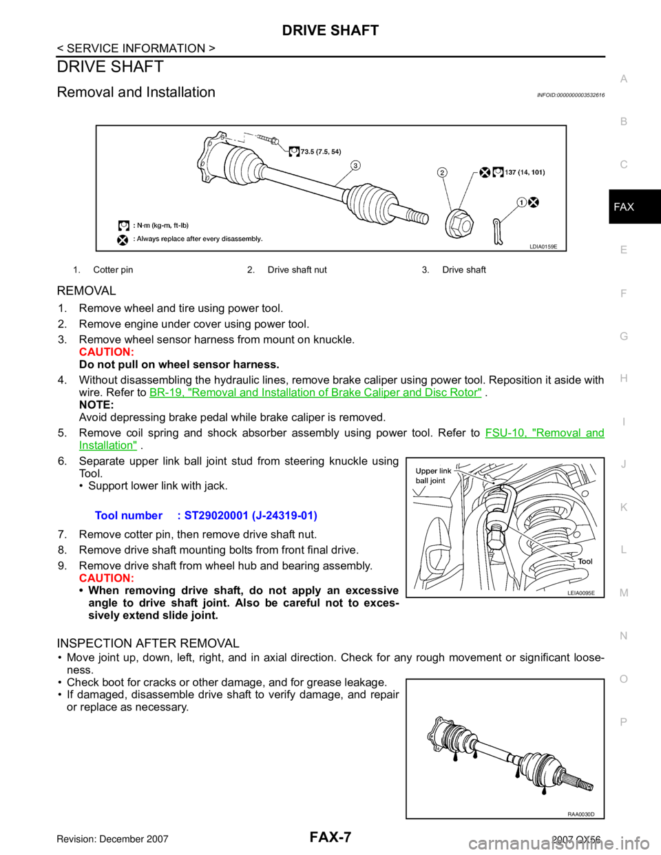
6. Separate upper link ball joint stud from steering knuckle using
Tool.
• Support lower link with jack.
7. Remove cotter pin, then remove drive shaft nut.
8. Remove drive shaft mounting bolts from front final drive.
9. Remove drive shaft from wheel hub and bearing assembly.
CAUTION:
• When removing drive shaft, do not apply an excessive
angle to drive shaft joint. Also be careful not to exces-
sively extend slide joint.
INSPECTION AFTER REMOVAL
• Move joint up, down, left, right, and in axial direction. Check for any rough movement or significant loose-
ness.
• Check boot for cracks or other damage, and for grease leakage.
• If damaged, disassemble drive shaft to verify damage, and repair
or replace as necessary.
1. Cotter pin 2. Drive shaft nut 3. Drive shaft
LDIA0159E
Tool number : ST29020001 (J-24319-01)
LEIA0095E
RAA0030D
Page 1900 of 3061
FFD-1
DRIVELINE/AXLE
C
E
F
G
H
I
J
K
L
M
SECTION FFD
A
B
FFD
N
O
P
CONTENTS
FRONT FINAL DRIVE
SERVICE INFORMATION ............................2
PRECAUTIONS ...................................................2
Precaution for Servicing Front Final Drive ................2
PREPARATION ...................................................3
Special Service Tool .................................................3
Commercial Service Tool ..........................................5
NOISE, VIBRATION AND HARSHNESS
(NVH) TROUBLESHOOTING .............................
6
NVH Troubleshooting Chart ......................................6
DIFFERENTIAL GEAR OIL .................................7
Changing Differential Gear Oil ..................................7
Checking Differential Gear Oil ...................................7
FRONT OIL SEAL ..............................................8
Removal and Installation ..........................................8
SIDE OIL SEAL .................................................10
Removal and Installation .........................................10
CARRIER COVER .............................................11
Removal and Installation .........................................11
FRONT FINAL DRIVE ASSEMBLY ..................12
Removal and Installation .........................................12
Disassembly and Assembly .....................................13
SERVICE DATA AND SPECIFICATIONS
(SDS) .................................................................
31
General Specification ..............................................31
Inspection and Adjustment ......................................31
Page 1901 of 3061
FFD-2
< SERVICE INFORMATION >
PRECAUTIONS
SERVICE INFORMATION
PRECAUTIONS
Precaution for Servicing Front Final DriveINFOID:0000000003532584
• Before starting diagnosis of the vehicle, understand the symptoms well. Perform correct and systematic
operations.
• Check for the correct installation status prior to removal or disassembly. When matching marks are required,
be certain they do not interfere with the function of the parts they are applied to.
• Overhaul should be done in a clean work area, a dust proof area is recommended.
• Before disassembly, completely remove sand and mud from the exterior of the unit, preventing them from
entering into the unit during disassembly or assembly.
• Always use shop paper for cleaning the inside of components.
• Avoid using cotton gloves or a shop cloth to prevent the entering of lint.
• Check appearance of the disassembled parts for damage, deformation, and abnormal wear. Replace them
with new ones if necessary.
• Gaskets, seals and O-rings should be replaced any time the unit is disassembled.
• Clean and flush the parts sufficiently and blow them dry.
• Be careful not to damage sliding surfaces and mating surfaces.
• When applying sealant, remove the old sealant from the mating surface; then remove any moisture, oil, and
foreign materials from the application and mating surfaces.
• In principle, tighten nuts or bolts gradually in several steps working diagonally from inside to outside. If a
tightening sequence is specified, observe it.
• During assembly, observe the specified tightening torque.
• Add new differential gear oil, petroleum jelly, or multi-purpose grease, as specified.
Page 1906 of 3061
DIFFERENTIAL GEAR OIL
FFD-7
< SERVICE INFORMATION >
C
E
F
G
H
I
J
K
L
MA
B
FFD
N
O
P
DIFFERENTIAL GEAR OIL
Changing Differential Gear OilINFOID:0000000003532588
DRAINING
1. Stop the engine.
2. Remove the drain plug from the front final drive assembly to drain the differential gear oil.
3. Install the drain plug with sealant applied on the threads to the front final drive assembly. Tighten to the
specified torque. Refer to FFD-13, "
Disassembly and Assembly".
• Use High Performance Thread Sealant or equivalent. Refer to GI-45, "
Recommended Chemical Product
and Sealant".
FILLING
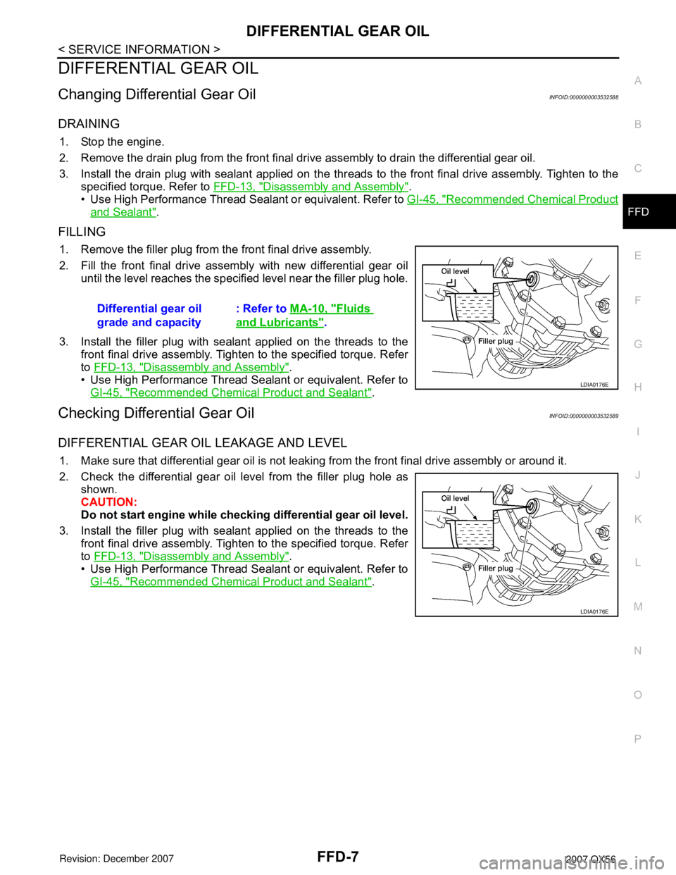
1. Remove the filler plug from the front final drive assembly.
2. Fill the front final drive assembly with new differential gear oil
until the level reaches the specified level near the filler plug hole.
3. Install the filler plug with sealant applied on the threads to the
front final drive assembly. Tighten to the specified torque. Refer
to FFD-13, "
Disassembly and Assembly".
• Use High Performance Thread Sealant or equivalent. Refer to
GI-45, "
Recommended Chemical Product and Sealant".
Checking Differential Gear OilINFOID:0000000003532589
DIFFERENTIAL GEAR OIL LEAKAGE AND LEVEL
1. Make sure that differential gear oil is not leaking from the front final drive assembly or around it.
2. Check the differential gear oil level from the filler plug hole as
shown.
CAUTION:
Do not start engine while checking differential gear oil level.
3. Install the filler plug with sealant applied on the threads to the
front final drive assembly. Tighten to the specified torque. Refer
to FFD-13, "
Disassembly and Assembly".
• Use High Performance Thread Sealant or equivalent. Refer to
GI-45, "
Recommended Chemical Product and Sealant". Differential gear oil
grade and capacity: Refer to MA-10, "
Fluids
and Lubricants".
LDIA0176E
LDIA0176E
Page 1908 of 3061
FRONT OIL SEAL
FFD-9
< SERVICE INFORMATION >
C
E
F
G
H
I
J
K
L
MA
B
FFD
N
O
P
INSTALLATION
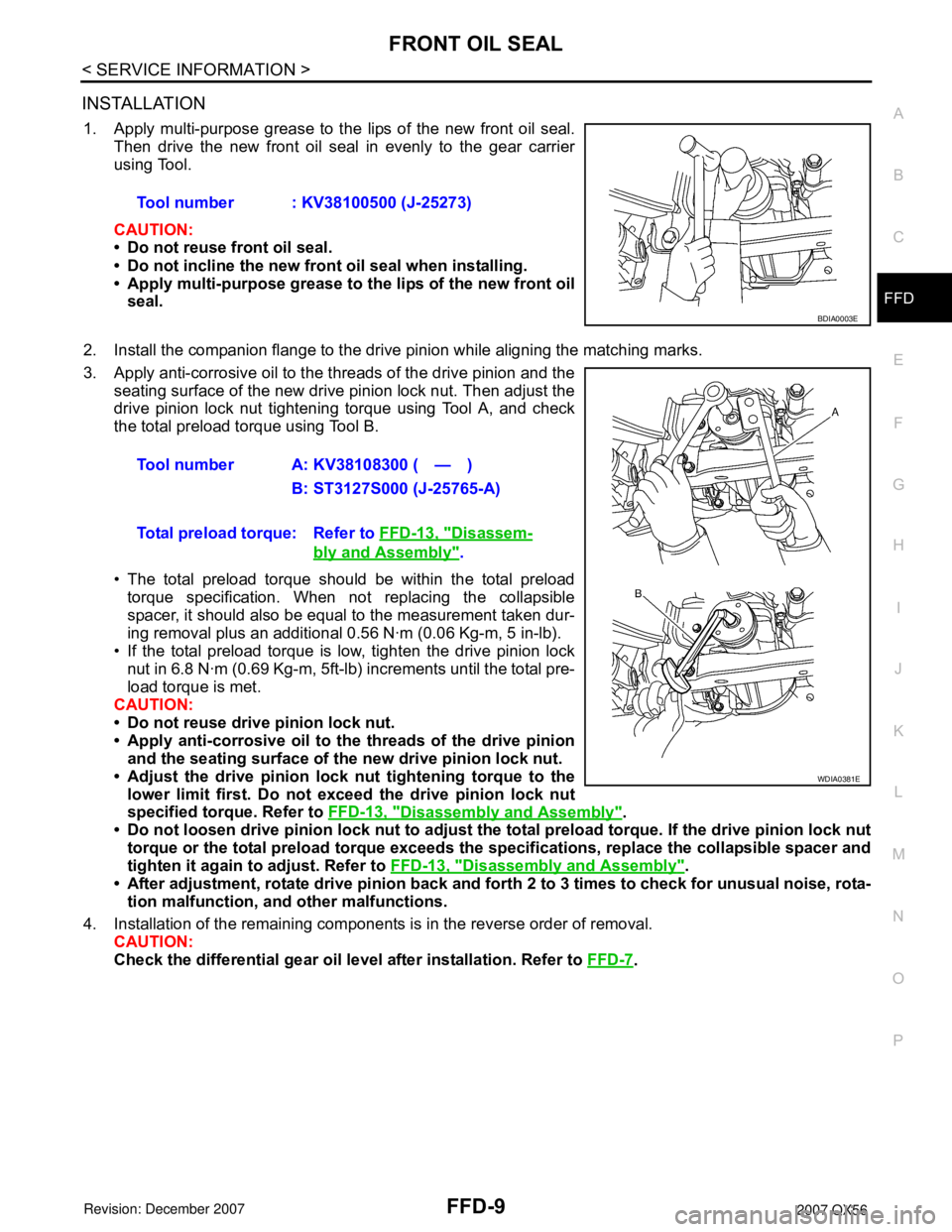
1. Apply multi-purpose grease to the lips of the new front oil seal.
Then drive the new front oil seal in evenly to the gear carrier
using Tool.
CAUTION:
• Do not reuse front oil seal.
• Do not incline the new front oil seal when installing.
• Apply multi-purpose grease to the lips of the new front oil
seal.
2. Install the companion flange to the drive pinion while aligning the matching marks.
3. Apply anti-corrosive oil to the threads of the drive pinion and the
seating surface of the new drive pinion lock nut. Then adjust the
drive pinion lock nut tightening torque using Tool A, and check
the total preload torque using Tool B.
• The total preload torque should be within the total preload
torque specification. When not replacing the collapsible
spacer, it should also be equal to the measurement taken dur-
ing removal plus an additional 0.56 N·m (0.06 Kg-m, 5 in-lb).
• If the total preload torque is low, tighten the drive pinion lock
nut in 6.8 N·m (0.69 Kg-m, 5ft-lb) increments until the total pre-
load torque is met.
CAUTION:
• Do not reuse drive pinion lock nut.
• Apply anti-corrosive oil to the threads of the drive pinion
and the seating surface of the new drive pinion lock nut.
• Adjust the drive pinion lock nut tightening torque to the
lower limit first. Do not exceed the drive pinion lock nut
specified torque. Refer to FFD-13, "
Disassembly and Assembly".
• Do not loosen drive pinion lock nut to adjust the total preload torque. If the drive pinion lock nut
torque or the total preload torque exceeds the specifications, replace the collapsible spacer and
tighten it again to adjust. Refer to FFD-13, "
Disassembly and Assembly".
• After adjustment, rotate drive pinion back and forth 2 to 3 times to check for unusual noise, rota-
tion malfunction, and other malfunctions.
4. Installation of the remaining components is in the reverse order of removal.
CAUTION:
Check the differential gear oil level after installation. Refer to FFD-7
. Tool number : KV38100500 (J-25273)
BDIA0003E
Tool number A: KV38108300 ( — )
B: ST3127S000 (J-25765-A)
Total preload torque: Refer to FFD-13, "
Disassem-
bly and Assembly".
WDIA0381E
Page 1909 of 3061
FFD-10
< SERVICE INFORMATION >
SIDE OIL SEAL
SIDE OIL SEAL
Removal and InstallationINFOID:0000000003532591
REMOVAL
1. Remove the front final drive assembly. Refer to FFD-12, "Removal and Installation".
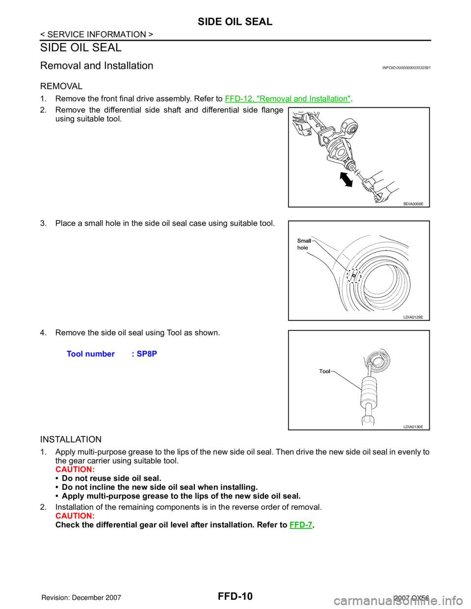
2. Remove the differential side shaft and differential side flange
using suitable tool.
3. Place a small hole in the side oil seal case using suitable tool.
4. Remove the side oil seal using Tool as shown.
INSTALLATION
1. Apply multi-purpose grease to the lips of the new side oil seal. Then drive the new side oil seal in evenly to
the gear carrier using suitable tool.
CAUTION:
• Do not reuse side oil seal.
• Do not incline the new side oil seal when installing.
• Apply multi-purpose grease to the lips of the new side oil seal.
2. Installation of the remaining components is in the reverse order of removal.
CAUTION:
Check the differential gear oil level after installation. Refer to FFD-7
.
BDIA0006E
LDIA0129E
Tool number : SP8P
LDIA0130E
Page 1916 of 3061
FRONT FINAL DRIVE ASSEMBLY
FFD-17
< SERVICE INFORMATION >
C
E
F
G
H
I
J
K
L
MA
B
FFD
N
O
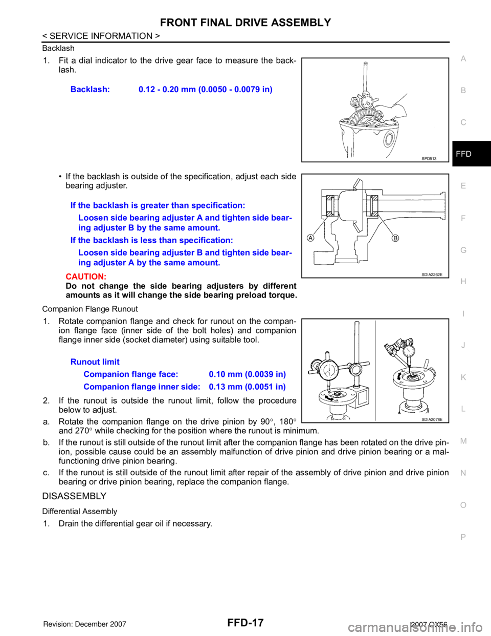
P Backlash
1. Fit a dial indicator to the drive gear face to measure the back-
lash.
• If the backlash is outside of the specification, adjust each side
bearing adjuster.
CAUTION:
Do not change the side bearing adjusters by different
amounts as it will change the side bearing preload torque.
Companion Flange Runout
1. Rotate companion flange and check for runout on the compan-
ion flange face (inner side of the bolt holes) and companion
flange inner side (socket diameter) using suitable tool.
2. If the runout is outside the runout limit, follow the procedure
below to adjust.
a. Rotate the companion flange on the drive pinion by 90°, 180°
and 270° while checking for the position where the runout is minimum.
b. If the runout is still outside of the runout limit after the companion flange has been rotated on the drive pin-
ion, possible cause could be an assembly malfunction of drive pinion and drive pinion bearing or a mal-
functioning drive pinion bearing.
c. If the runout is still outside of the runout limit after repair of the assembly of drive pinion and drive pinion
bearing or drive pinion bearing, replace the companion flange.
DISASSEMBLY
Differential Assembly
1. Drain the differential gear oil if necessary.Backlash: 0.12 - 0.20 mm (0.0050 - 0.0079 in)
SPD513
If the backlash is greater than specification:
Loosen side bearing adjuster A and tighten side bear-
ing adjuster B by the same amount.
If the backlash is less than specification:
Loosen side bearing adjuster B and tighten side bear-
ing adjuster A by the same amount.
SDIA2262E
Runout limit
Companion flange face: 0.10 mm (0.0039 in)
Companion flange inner side: 0.13 mm (0.0051 in)
SDIA2078E
Page 1926 of 3061
FRONT FINAL DRIVE ASSEMBLY
FFD-27
< SERVICE INFORMATION >
C
E
F
G
H
I
J
K
L
MA
B
FFD
N
O
P
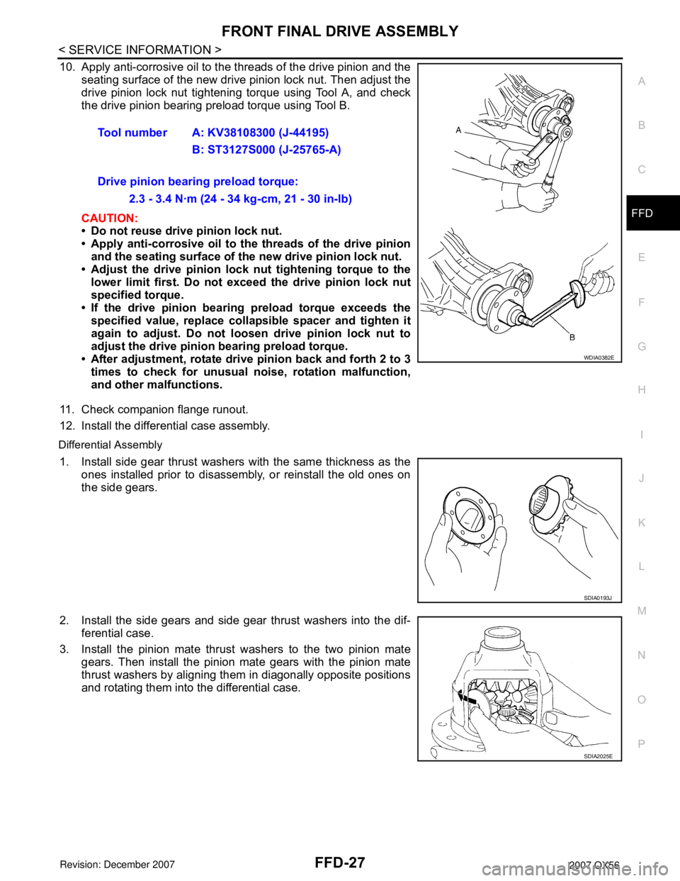
10. Apply anti-corrosive oil to the threads of the drive pinion and the
seating surface of the new drive pinion lock nut. Then adjust the
drive pinion lock nut tightening torque using Tool A, and check
the drive pinion bearing preload torque using Tool B.
CAUTION:
• Do not reuse drive pinion lock nut.
• Apply anti-corrosive oil to the threads of the drive pinion
and the seating surface of the new drive pinion lock nut.
• Adjust the drive pinion lock nut tightening torque to the
lower limit first. Do not exceed the drive pinion lock nut
specified torque.
• If the drive pinion bearing preload torque exceeds the
specified value, replace collapsible spacer and tighten it
again to adjust. Do not loosen drive pinion lock nut to
adjust the drive pinion bearing preload torque.
• After adjustment, rotate drive pinion back and forth 2 to 3
times to check for unusual noise, rotation malfunction,
and other malfunctions.
11. Check companion flange runout.
12. Install the differential case assembly.
Differential Assembly
1. Install side gear thrust washers with the same thickness as the
ones installed prior to disassembly, or reinstall the old ones on
the side gears.
2. Install the side gears and side gear thrust washers into the dif-
ferential case.
3. Install the pinion mate thrust washers to the two pinion mate
gears. Then install the pinion mate gears with the pinion mate
thrust washers by aligning them in diagonally opposite positions
and rotating them into the differential case.Tool number A: KV38108300 (J-44195)
B: ST3127S000 (J-25765-A)
Drive pinion bearing preload torque:
2.3 - 3.4 N·m (24 - 34 kg-cm, 21 - 30 in-lb)
WDIA0382E
SDIA0193J
SDIA2025E