2007 INFINITI QX56 check oil
[x] Cancel search: check oilPage 1928 of 3061
FRONT FINAL DRIVE ASSEMBLY
FFD-29
< SERVICE INFORMATION >
C
E
F
G
H
I
J
K
L
MA
B
FFD
N
O
P
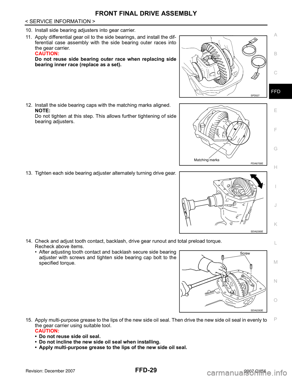
10. Install side bearing adjusters into gear carrier.
11. Apply differential gear oil to the side bearings, and install the dif-
ferential case assembly with the side bearing outer races into
the gear carrier.
CAUTION:
Do not reuse side bearing outer race when replacing side
bearing inner race (replace as a set).
12. Install the side bearing caps with the matching marks aligned.
NOTE:
Do not tighten at this step. This allows further tightening of side
bearing adjusters.
13. Tighten each side bearing adjuster alternately turning drive gear.
14. Check and adjust tooth contact, backlash, drive gear runout and total preload torque.
Recheck above items.
• After adjusting tooth contact and backlash secure side bearing
adjuster with screws and tighten side bearing cap bolt to the
specified torque.
15. Apply multi-purpose grease to the lips of the new side oil seal. Then drive the new side oil seal in evenly to
the gear carrier using suitable tool.
CAUTION:
• Do not reuse side oil seal.
• Do not incline the new side oil seal when installing.
• Apply multi-purpose grease to the lips of the new side oil seal.
SPD527
PDIA0700E
SDIA2265E
SDIA2263E
Page 1948 of 3061
FSU-2
< SERVICE INFORMATION >
PRECAUTIONS
SERVICE INFORMATION
PRECAUTIONS
PrecautionINFOID:0000000003532631
• When installing the rubber bushings, the final tightening must be done under unladen condition and with the
tires on level ground. Oil will shorten the life of the rubber bushings, so wipe off any spilled oil immediately.
• Unladen condition means the fuel tank, engine coolant and lubricants are at the full specification. The spare
tire, jack, hand tools, and mats are in their designated positions.
• After installing suspension components, check the wheel alignment.
• Lock nuts are not reusable. Always use new lock nuts for installation. New lock nuts are pre-oiled, do not
apply any additional lubrication.
Page 1952 of 3061
FSU-6
< SERVICE INFORMATION >
ON-VEHICLE SERVICE
ON-VEHICLE SERVICE
Front Suspension PartsINFOID:0000000003532636
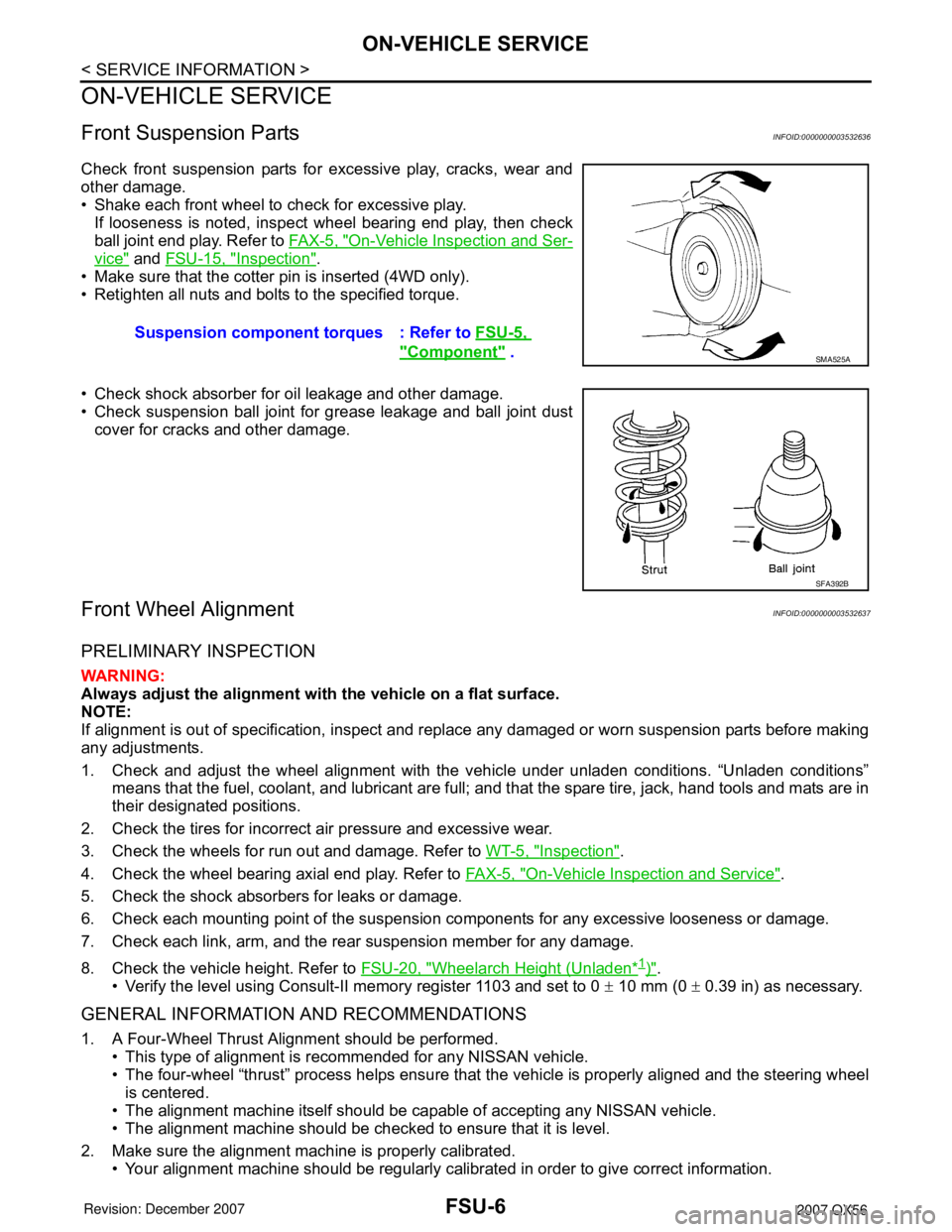
Check front suspension parts for excessive play, cracks, wear and
other damage.
• Shake each front wheel to check for excessive play.
If looseness is noted, inspect wheel bearing end play, then check
ball joint end play. Refer to FA X - 5 , "
On-Vehicle Inspection and Ser-
vice" and FSU-15, "Inspection".
• Make sure that the cotter pin is inserted (4WD only).
• Retighten all nuts and bolts to the specified torque.
• Check shock absorber for oil leakage and other damage.
• Check suspension ball joint for grease leakage and ball joint dust
cover for cracks and other damage.
Front Wheel AlignmentINFOID:0000000003532637
PRELIMINARY INSPECTION
WARNING:
Always adjust the alignment with the vehicle on a flat surface.
NOTE:
If alignment is out of specification, inspect and replace any damaged or worn suspension parts before making
any adjustments.
1. Check and adjust the wheel alignment with the vehicle under unladen conditions. “Unladen conditions”
means that the fuel, coolant, and lubricant are full; and that the spare tire, jack, hand tools and mats are in
their designated positions.
2. Check the tires for incorrect air pressure and excessive wear.
3. Check the wheels for run out and damage. Refer to WT-5, "
Inspection".
4. Check the wheel bearing axial end play. Refer to FA X - 5 , "
On-Vehicle Inspection and Service".
5. Check the shock absorbers for leaks or damage.
6. Check each mounting point of the suspension components for any excessive looseness or damage.
7. Check each link, arm, and the rear suspension member for any damage.
8. Check the vehicle height. Refer to FSU-20, "
Wheelarch Height (Unladen*1)".
• Verify the level using Consult-II memory register 1103 and set to 0 ± 10 mm (0 ± 0.39 in) as necessary.
GENERAL INFORMATION AND RECOMMENDATIONS
1. A Four-Wheel Thrust Alignment should be performed.
• This type of alignment is recommended for any NISSAN vehicle.
• The four-wheel “thrust” process helps ensure that the vehicle is properly aligned and the steering wheel
is centered.
• The alignment machine itself should be capable of accepting any NISSAN vehicle.
• The alignment machine should be checked to ensure that it is level.
2. Make sure the alignment machine is properly calibrated.
• Your alignment machine should be regularly calibrated in order to give correct information.Suspension component torques : Refer to FSU-5,
"Component" . SMA525A
SFA392B
Page 1957 of 3061
COIL SPRING AND SHOCK ABSORBER
FSU-11
< SERVICE INFORMATION >
C
D
F
G
H
I
J
K
L
MA
B
FSU
N
O
P
INSPECTION AFTER DISASSEMBLY
Shock Absorber Assembly
• Check for smooth operation through a full stroke, both compression and extension.
• Check for oil leakage on welded or gland packing portions.
• Check piston rod for cracks, deformation or other damage and replace if necessary.
Mounting Insulator and Rubber Parts
Check cemented rubber-to-metal portion for separation or cracks. Check rubber parts for deterioration and
replace if necessary.
Coil Spring
• Check for cracks, deformation or other damage and replace if necessary.
• Check the free spring height.
ASSEMBLY
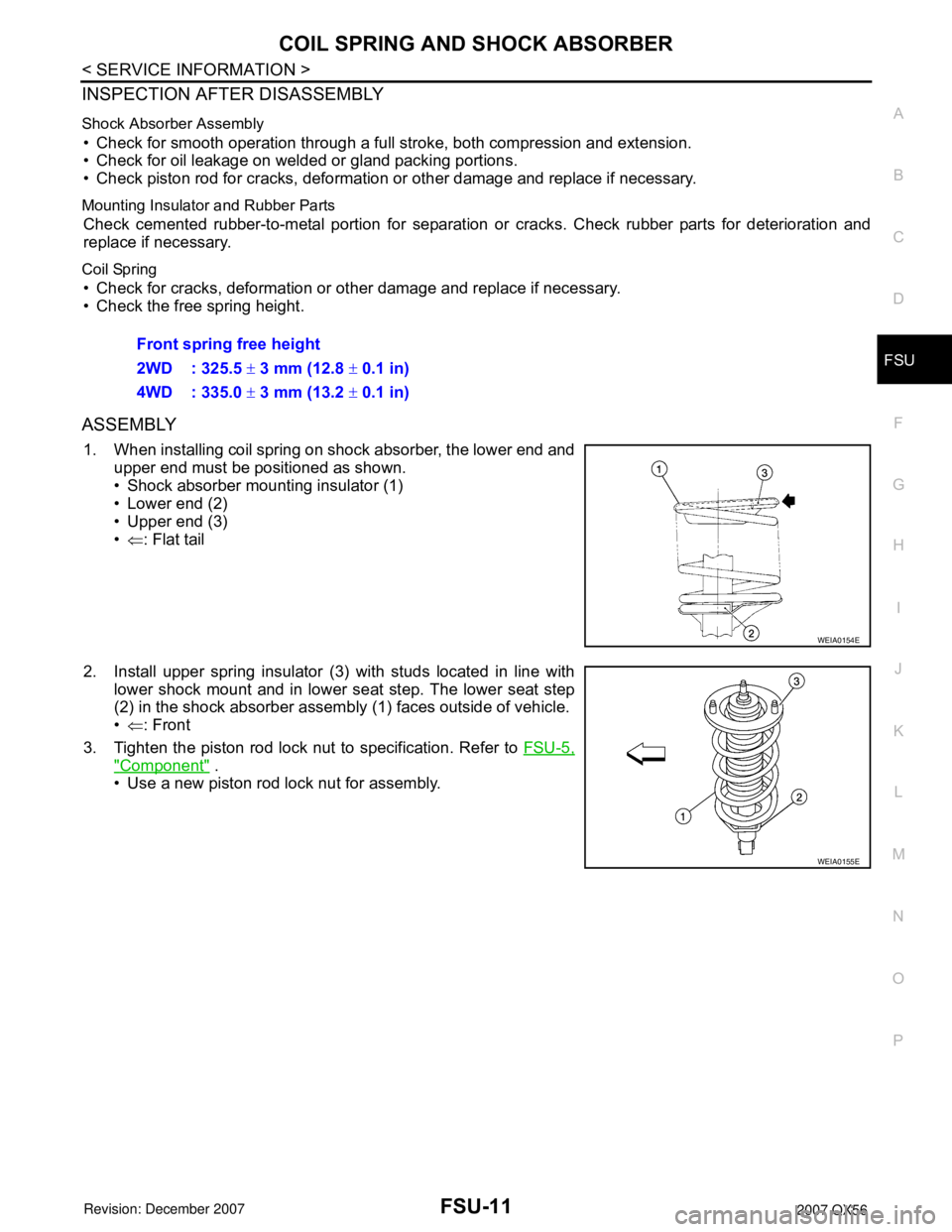
1. When installing coil spring on shock absorber, the lower end and
upper end must be positioned as shown.
• Shock absorber mounting insulator (1)
• Lower end (2)
• Upper end (3)
•⇐: Flat tail
2. Install upper spring insulator (3) with studs located in line with
lower shock mount and in lower seat step. The lower seat step
(2) in the shock absorber assembly (1) faces outside of vehicle.
•⇐: Front
3. Tighten the piston rod lock nut to specification. Refer to FSU-5,
"Component" .
• Use a new piston rod lock nut for assembly.Front spring free height
2WD : 325.5 ± 3 mm (12.8 ± 0.1 in)
4WD : 335.0 ± 3 mm (13.2 ± 0.1 in)
WEIA0154E
WEIA0155E
Page 1967 of 3061
GI-1
GENERAL INFORMATION
C
D
E
F
G
H
I
J
K
L
MB
GI
SECTION GI
N
O
P
CONTENTS
GENERAL INFORMATION
SERVICE INFORMATION ............................2
PRECAUTIONS ...................................................2
Description ................................................................2
Precaution for Supplemental Restraint System
(SRS) "AIR BAG" and "SEAT BELT PRE-TEN-
SIONER" ...................................................................
2
Precaution for NVIS/IVIS (NISSAN/INFINITI VE-
HICLE IMMOBILIZER SYSTEM - NATS) (If
Equipped) ..................................................................
2
General Precaution ...................................................3
Precaution for Three Way Catalyst ...........................4
Precaution for Fuel (Unleaded Premium Gasoline
Required) ..................................................................
4
Precaution for Multiport Fuel Injection System or
Engine Control System .............................................
5
Precaution for Hoses .................................................5
Precaution for Engine Oils ........................................6
Precaution for Air Conditioning .................................6
HOW TO USE THIS MANUAL ............................7
Description ................................................................7
Terms ........................................................................7
Units ..........................................................................7
Relation between Illustrations and Descriptions .......7
Contents ....................................................................8
Component ................................................................8
How to Follow Trouble Diagnosis ..............................9
How to Read Wiring Diagram ..................................13
Abbreviations ..........................................................20
SERVICE INFORMATION FOR ELECTRICAL
INCIDENT ...........................................................
22
How to Check Terminal ...........................................22
How to Perform Efficient Diagnosis for an Electri-
cal Incident ..............................................................
25
Control Units and Electrical Parts ............................32
CONSULT-II CHECKING SYSTEM ..................35
Description ...............................................................35
Function and System Application ............................35
Nickel Metal Hydride Battery Replacement .............36
Checking Equipment ...............................................36
CONSULT-II Start Procedure ..................................36
CONSULT-II Data Link Connector (DLC) Circuit .....38
LIFTING POINT .................................................40
Pantograph Jack ......................................................40
Garage Jack and Safety Stand ................................40
2-Pole Lift ................................................................40
TOW TRUCK TOWING .....................................42
Tow Truck Towing ...................................................42
Vehicle Recovery (Freeing a stuck vehicle) ............43
TIGHTENING TORQUE OF STANDARD
BOLTS ...............................................................
44
Tightening Torque Table .........................................44
RECOMMENDED CHEMICAL PRODUCTS
AND SEALANTS ...............................................
45
Recommended Chemical Product and Sealant .......45
IDENTIFICATION INFORMATION ....................46
Model Variation ........................................................46
Identification Number ...............................................47
Dimensions ..............................................................48
Wheels & Tires ........................................................48
TERMINOLOGY ................................................50
SAE J1930 Terminology List ...................................50
Page 1970 of 3061
GI-4
< SERVICE INFORMATION >
PRECAUTIONS
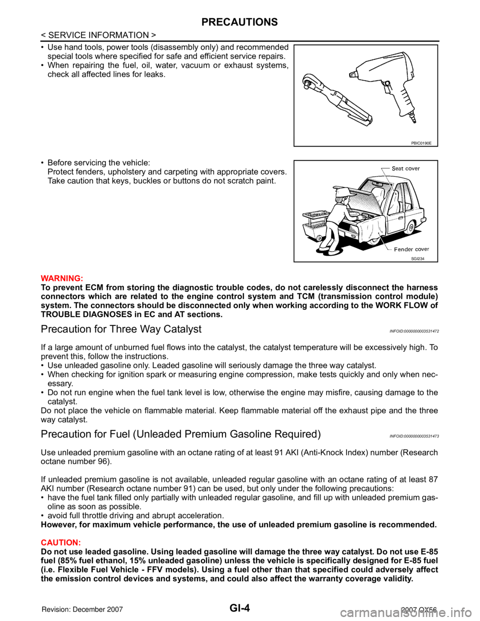
• Use hand tools, power tools (disassembly only) and recommended
special tools where specified for safe and efficient service repairs.
• When repairing the fuel, oil, water, vacuum or exhaust systems,
check all affected lines for leaks.
• Before servicing the vehicle:
Protect fenders, upholstery and carpeting with appropriate covers.
Take caution that keys, buckles or buttons do not scratch paint.
WARNING:
To prevent ECM from storing the diagnostic trouble codes, do not carelessly disconnect the harness
connectors which are related to the engine control system and TCM (transmission control module)
system. The connectors should be disconnected only when working according to the WORK FLOW of
TROUBLE DIAGNOSES in EC and AT sections.
Precaution for Three Way CatalystINFOID:0000000003531472
If a large amount of unburned fuel flows into the catalyst, the catalyst temperature will be excessively high. To
prevent this, follow the instructions.
• Use unleaded gasoline only. Leaded gasoline will seriously damage the three way catalyst.
• When checking for ignition spark or measuring engine compression, make tests quickly and only when nec-
essary.
• Do not run engine when the fuel tank level is low, otherwise the engine may misfire, causing damage to the
catalyst.
Do not place the vehicle on flammable material. Keep flammable material off the exhaust pipe and the three
way catalyst.
Precaution for Fuel (Unleaded Premium Gasoline Required)INFOID:0000000003531473
Use unleaded premium gasoline with an octane rating of at least 91 AKI (Anti-Knock Index) number (Research
octane number 96).
If unleaded premium gasoline is not available, unleaded regular gasoline with an octane rating of at least 87
AKI number (Research octane number 91) can be used, but only under the following precautions:
• have the fuel tank filled only partially with unleaded regular gasoline, and fill up with unleaded premium gas-
oline as soon as possible.
• avoid full throttle driving and abrupt acceleration.
However, for maximum vehicle performance, the use of unleaded premium gasoline is recommended.
CAUTION:
Do not use leaded gasoline. Using leaded gasoline will damage the three way catalyst. Do not use E-85
fuel (85% fuel ethanol, 15% unleaded gasoline) unless the vehicle is specifically designed for E-85 fuel
(i.e. Flexible Fuel Vehicle - FFV models). Using a fuel other than that specified could adversely affect
the emission control devices and systems, and could also affect the warranty coverage validity.
PBIC0190E
SGI234
Page 2099 of 3061
GW-80
< SERVICE INFORMATION >
REAR WINDOW DEFOGGER
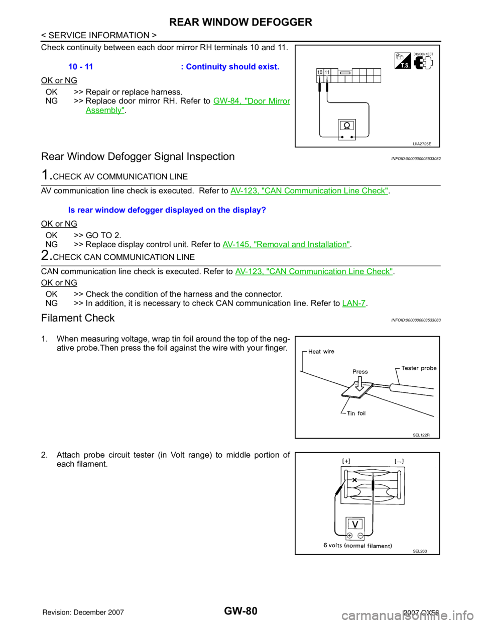
Check continuity between each door mirror RH terminals 10 and 11.
OK or NG
OK >> Repair or replace harness.
NG >> Replace door mirror RH. Refer to GW-84, "
Door Mirror
Assembly".
Rear Window Defogger Signal InspectionINFOID:0000000003533082
1.CHECK AV COMMUNICATION LINE
AV communication line check is executed. Refer to AV-123, "
CAN Communication Line Check".
OK or NG
OK >> GO TO 2.
NG >> Replace display control unit. Refer to AV-145, "
Removal and Installation".
2.CHECK CAN COMMUNICATION LINE
CAN communication line check is executed. Refer to AV-123, "
CAN Communication Line Check".
OK or NG
OK >> Check the condition of the harness and the connector.
NG >> In addition, it is necessary to check CAN communication line. Refer to LAN-7
.
Filament CheckINFOID:0000000003533083
1. When measuring voltage, wrap tin foil around the top of the neg-
ative probe.Then press the foil against the wire with your finger.
2. Attach probe circuit tester (in Volt range) to middle portion of
each filament.10 - 11 : Continuity should exist.
LIIA2725E
Is rear window defogger displayed on the display?
SEL122R
SEL263
Page 2106 of 3061
IDX-2
ALPHABETICAL INDEX
Numerics
2-4WD shift solenoid valve ..... TF-93
, TF-154, TF-167
4WD - Wiring diagram ....................................... TF-24
4WD shift switch ................................................ TF-65
4WD solenoid valve ................ TF-89, TF-154, TF-167
4WD system description .................................... TF-15
4WD system diagram ........................................ TF-19
A
A/C air flow ...................................................... ATC-30
A/C compressor clutch removal and installation .. ATC-
180
A/C compressor mounting ............................. ATC-179
A/C compressor precaution ............................. ATC-11
A/C compressor special service tool ................ ATC-14
A/C control operation (auto A/C) ...................... ATC-27
A/C diagnostic work flow (auto A/C) .............. ATC-133
A/C evaporator ............................................... ATC-186
A/C HFC134a (R134a) system identification ..... ATC-6
A/C HFC134a (R134a) system precaution ........ ATC-5
A/C HFC134a (R134a) system service procedure ATC-
175
A/C HFC134a (R134a) system service tools ... ATC-14
A/C HFC134a system service equipment precaution ...
ATC-11
A/C lubricant (R134a) ...................................... ATC-22
A/C lubrication oil ............................................. ATC-22
A/C operational check ....................... ATC-56, ATC-58
A/C self-diagnoses (auto A/C) ........ ATC-54, ATC-133
A/C service data specification ........................ ATC-193
A/C trouble diagnoses (auto A/C) .................... ATC-34
A/C, A - Wiring diagram ................................... ATC-42
A/T fluid checking ...................... AT-12, AT-51, MA-22
A/T fluid cooler cleaning .................................... AT-14
A/T fluid replacement ............................. AT-12, MA-24
A/T fluid temperature sensor ........................... AT-123
A/T IND - Wiring diagram .................................... DI-36
A/T indicator ........................................................ DI-36
A/T shift lock system ........................................ AT-216
A/T trouble diagnoses ........................................ AT-42
ABS - Wiring diagram ..................................... BRC-16
ABS (anti-lock brake system) ........................... BRC-7
Accelerator control system ............................... ACC-3
Accelerator pedal position (APP) sensor . EC-608, EC-
614, EC-628
Accelerator pedal released position learning ..... EC-80
AF1B1-Wiring diagram EC-242, EC-250, EC-258, EC-
267, EC-638
AF1B2-Wiring diagram EC-244, EC-252, EC-260, EC-
269, EC-640
AF1HB1-Wiring diagram .................................. EC-175
AF1HB2-Wiring diagram .................................. EC-177
Aiming adjustment .................................. LT-23, LT-61
Air bag .............................................................. SRS-3
Air bag precautions .............................................. AV-4
Air cleaner and air duct ..................................... EM-15
Air cleaner filter replacement ................ EM-16, MA-16
Air conditioner cut control ................................. EC-29
Air flow meter - See Mass air flow sensor EC-197, EC-
206
Air fuel ratio sensor 1 .. EC-239, EC-248, EC-256, EC-
264, EC-636
Air fuel ratio sensor 1 heater ........................... EC-174
Air mix. door motor .......................................... ATC-69
Ambient sensor ............................. ATC-138, ATC-149
Angular tightening application ............................. EM-4
Antenna .............................................................. AV-58
APPS1 - Wiring diagram ................................. EC-610
APPS2 - Wiring diagram ................................. EC-616
APPS3 - Wiring diagram ................................. EC-630
ASC/BS - Wiring diagram ............................... EC-574
ASC/SW - Wiring diagram .............................. EC-557
ASCBOF - Wiring diagram .............................. EC-648
ASCD ................................................................ EC-30
ASCD (automatic speed control device) ........... ACS-3
ASCD brake switch ........................... EC-572, EC-647
ASCD indicator lamp ....................................... EC-654
ASCD steering switch ..................................... EC-555
ASCIND - Wiring diagram ............................... EC-655
ATP switch ............................ TF-106, TF-109, TF-114
Audio .................................................................... AV-6
AUDIO - Wiring diagram .................................... AV-11
AUT/DP - Wiring diagram .................................. SE-16
Auto air conditioner - Wiring diagram .............. ATC-42
Auto anti-dazzling inside mirror ........... GW-69, GW-70
Autolamp ............................................................ LT-38
Automatic amplifier ......................................... ATC-59
Automatic drive positioner .................................. SE-11
Automatic transmission number .......................... GI-50
B
Back door ........................................................... BL-88
Back door trim ..................................................... EI-32
Back sonar .......................................................... DI-50
BACK/L - Wiring diagram ................................... LT-87
Back-up lamp ..................................................... LT-87
Ball joint (front) ................................................ FSU-15
Basic inspection ................................................ EC-73
Battery ................................................................. SC-4
Battery current sensor . EC-520, EC-527, EC-534, EC-
541
Battery/Starting/Charging System Tester SC-6, SC-12,
SC-20
BCM (Body control module) ................ BCS-3, AV-106
Block heater ...................................................... EM-78
Blower motor ................................... ATC-93, ATC-153
Body alignment ................................................ BL-164
Body component parts ..................................... BL-151
Body construction ............................................ BL-163
Body exterior paint color .................................. BL-150
Body mounting ................................................. BL-149
Body repair ....................................................... BL-150
Body sealing .................................................... BL-160
Bose speaker amp. .............................................. AV-8
Brake booster .................................................... BR-17