Page 4060 of 4647
SUNROOF
RF-19
C
D
E
F
G
H
J
K
L
MA
B
RF
Revision: 2007 April2007 M35/M45
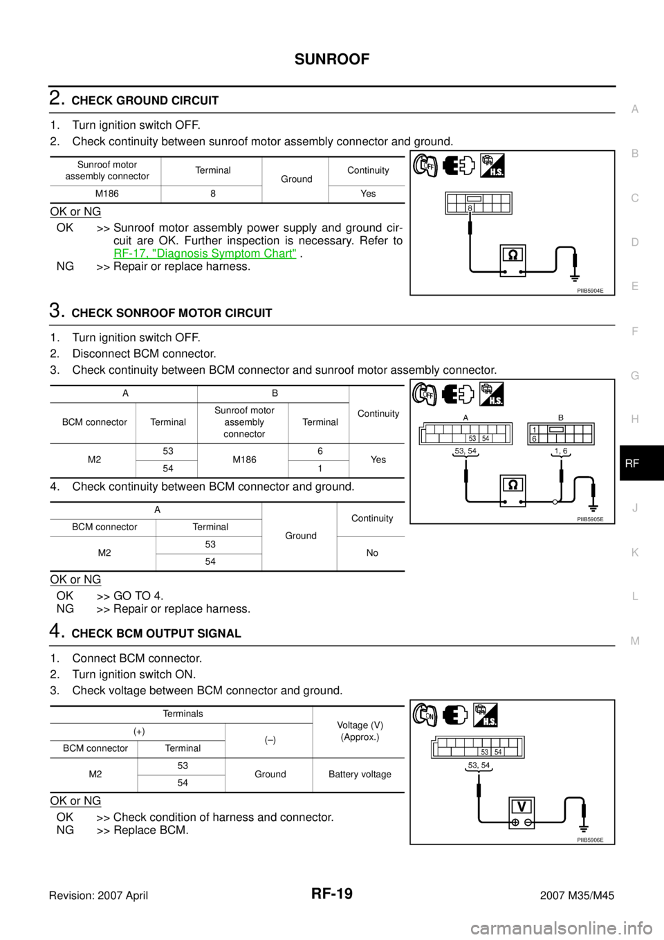
2. CHECK GROUND CIRCUIT
1. Turn ignition switch OFF.
2. Check continuity between sunroof motor assembly connector and ground.
OK or NG
OK >> Sunroof motor assembly power supply and ground cir-
cuit are OK. Further inspection is necessary. Refer to
RF-17, "
Diagnosis Symptom Chart" .
NG >> Repair or replace harness.
3. CHECK SONROOF MOTOR CIRCUIT
1. Turn ignition switch OFF.
2. Disconnect BCM connector.
3. Check continuity between BCM connector and sunroof motor assembly connector.
4. Check continuity between BCM connector and ground.
OK or NG
OK >> GO TO 4.
NG >> Repair or replace harness.
4. CHECK BCM OUTPUT SIGNAL
1. Connect BCM connector.
2. Turn ignition switch ON.
3. Check voltage between BCM connector and ground.
OK or NG
OK >> Check condition of harness and connector.
NG >> Replace BCM.
Sunroof motor
assembly connectorTerminal
GroundContinuity
M186 8 Yes
PIIB5904E
AB
Continuity
BCM connector TerminalSunroof motor
assembly
connectorTerminal
M253
M1866
Ye s
54 1
A
GroundContinuity
BCM connector Terminal
M253
No
54
PIIB5905E
Terminals
Voltage (V)
(Approx.) (+)
(–)
BCM connector Terminal
M253
Ground Battery voltage
54
PIIB5906E
Page 4061 of 4647
RF-20
SUNROOF
Revision: 2007 April2007 M35/M45
Check Sunroof Switch NIS00240
1. CHECK SUNROOF SWITCH INPUT SIGNAL
1. Turn ignition switch ON.
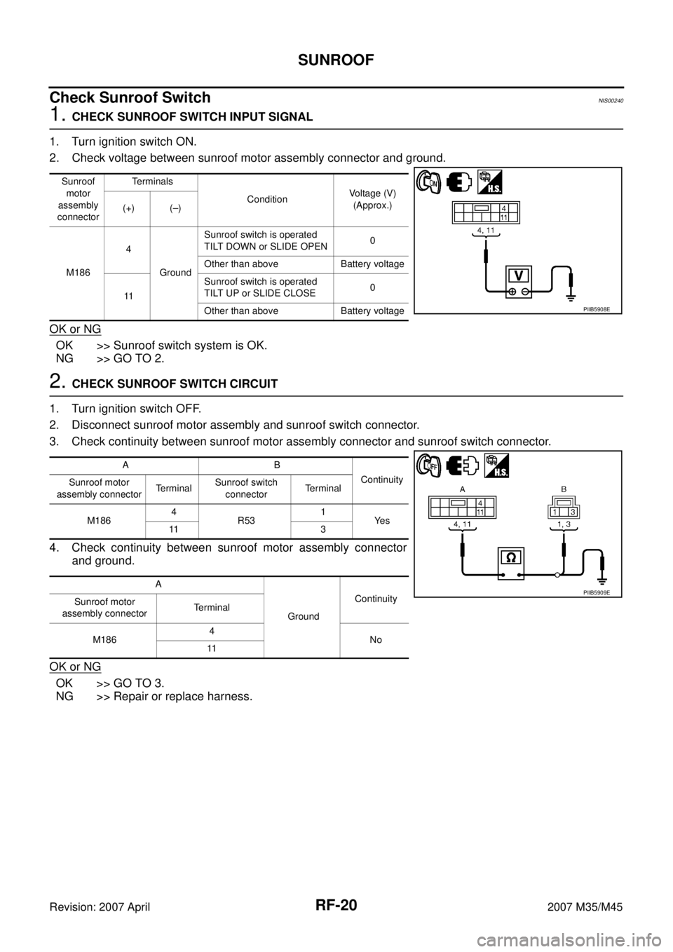
2. Check voltage between sunroof motor assembly connector and ground.
OK or NG
OK >> Sunroof switch system is OK.
NG >> GO TO 2.
2. CHECK SUNROOF SWITCH CIRCUIT
1. Turn ignition switch OFF.
2. Disconnect sunroof motor assembly and sunroof switch connector.
3. Check continuity between sunroof motor assembly connector and sunroof switch connector.
4. Check continuity between sunroof motor assembly connector
and ground.
OK or NG
OK >> GO TO 3.
NG >> Repair or replace harness.
Sunroof
motor
assembly
connectorTerminals
ConditionVoltage (V)
(Approx.)
(+) (–)
M1864
GroundSunroof switch is operated
TILT DOWN or SLIDE OPEN0
Other than above Battery voltage
11Sunroof switch is operated
TILT UP or SLIDE CLOSE0
Other than above Battery voltage
PIIB5908E
AB
Continuity
Sunroof motor
assembly connectorTerminalSunroof switch
connectorTerminal
M1864
R531
Ye s
11 3
A
GroundContinuity
Sunroof motor
assembly connectorTerminal
M1864
No
11
PIIB5909E
Page 4063 of 4647
RF-22
SUNROOF
Revision: 2007 April2007 M35/M45
Check Door SwitchNIS00241
1. CHECK DOOR SWITCH INPUT SIGNAL
Check voltage between BCM connector and ground.
OK or NG
OK >> Door switch circuit is OK.
NG >> GO TO 2.
2. CHECK DOOR SWITCH CIRCUIT
1. Turn ignition switch OFF.
2. Disconnect door switch and BCM connector.
3. Check continuity between BCM connector and door switch connector.
4. Check continuity between BCM connector and ground.
OK or NG
OK >> GO TO 3.
NG >> Repair or replace harness.
BCM
connectorItemTerminals
ConditionVoltage (V)
(Approx.)
(+) (–)
M1 Passenger side 12
GroundOPEN 0
CLOSE Battery voltage
M3 Driver side 62OPEN 0
CLOSE Battery voltage
PIIB5912E
AB
Continuity
BCM connector TerminalDriver side door
switch connectorTerminal
M3 62 B11 2 Yes
AC
Continuity
BCM connector TerminalPassenger side
door switch
connectorTerminal
M1 12 B424 2 Yes
A
GroundContinuity
BCM
connectorItem Terminal
M3 Driver side 62
No
M1Passenger
side12
PIIB6494E
Page 4143 of 4647
SB-18
PRE-CRASH SEAT BELT
Revision: 2007 April2007 M35/M45
Check Seat Belt Buckle Switch (Driver Side) Circuit NHS0008B
1. CHECK PRE-CRASH SEAT BELT CONTROL UNIT INPUT SIGNAL
With CONSULT-II
Select “SB SW LH SIG” on DATA MONITOR screen, and then make sure that ON/OFF display changes syn-
chronized with the insertion operation to the seat belt buckle.
Without CONSULT-II
1. Turn ignition switch ON.
2. Check voltage between seat belt buckle switch (driver side) har-
ness connector and ground.
OK or NG
OK >> Seat belt buckle switch (driver side) circuit is OK.
NG >> GO TO 2.SB SW LH SIG
When driver seat belt is not fastened : OFF
When driver seat belt is fastened : ON
PHIA0765E
Terminal
ConditionVoltage (V)
(Approx.) (+)
(–) Seat belt buckle
switch connector
(driver side)Terminal
B203 1 GroundWhen seat belt is
unfastened0
When seat belt is
fastenedBattery
voltage
PHIA1129E
Page 4145 of 4647
SB-20
PRE-CRASH SEAT BELT
Revision: 2007 April2007 M35/M45
Check Seat Belt Buckle Switch (Passenger Side) Circuit NHS0008C
1. CHECK PRE-CRASH SEAT BELT CONTROL UNIT INPUT SIGNAL
With CONSULT-II
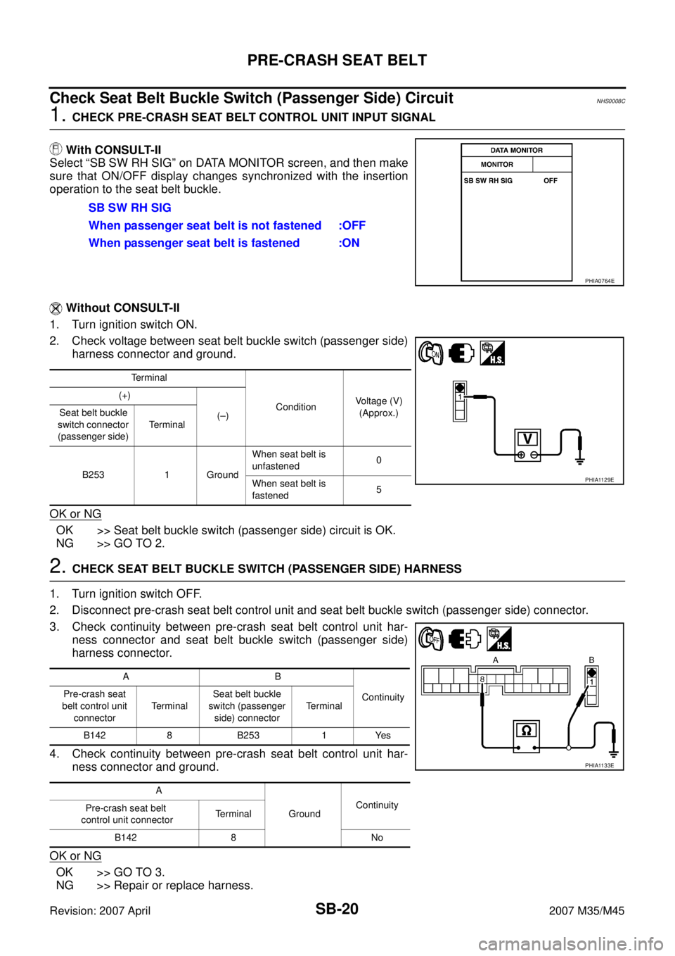
Select “SB SW RH SIG” on DATA MONITOR screen, and then make
sure that ON/OFF display changes synchronized with the insertion
operation to the seat belt buckle.
Without CONSULT-II
1. Turn ignition switch ON.
2. Check voltage between seat belt buckle switch (passenger side)
harness connector and ground.
OK or NG
OK >> Seat belt buckle switch (passenger side) circuit is OK.
NG >> GO TO 2.
2. CHECK SEAT BELT BUCKLE SWITCH (PASSENGER SIDE) HARNESS
1. Turn ignition switch OFF.
2. Disconnect pre-crash seat belt control unit and seat belt buckle switch (passenger side) connector.
3. Check continuity between pre-crash seat belt control unit har-
ness connector and seat belt buckle switch (passenger side)
harness connector.
4. Check continuity between pre-crash seat belt control unit har-
ness connector and ground.
OK or NG
OK >> GO TO 3.
NG >> Repair or replace harness.SB SW RH SIG
When passenger seat belt is not fastened :OFF
When passenger seat belt is fastened :ON
PHIA0764E
Terminal
ConditionVoltage (V)
(Approx.) (+)
(–) Seat belt buckle
switch connector
(passenger side) Terminal
B253 1 GroundWhen seat belt is
unfastened0
When seat belt is
fastened5
PHIA1129E
AB
Continuity Pre-crash seat
belt control unit
connectorTe r m i n a lSeat belt buckle
switch (passenger
side) connectorTerminal
B142 8 B253 1 Yes
A
GroundContinuity
Pre-crash seat belt
control unit connectorTerminal
B142 8 No
PHIA1133E
Page 4147 of 4647
SB-22
PRE-CRASH SEAT BELT
Revision: 2007 April2007 M35/M45
2. CHECK PRE-CRASH SEAT BELT CONTOROL UNIT INPUT SIGNAL
With CONSULT-II
Select “B PEDAL SIG1” and “B PEDAL SIG2”, and then make sure that the voltage changes synchronized
with brake pedal operation.
Without CONSULT-II
1. Turn ignition switch ON.
2. Check voltage between pre-crash seat belt control unit harness
connector and ground.
OK or NG
OK >> Brake pedal stroke sensor system is normal.
NG >> GO TO 3.B PEDAL SIG1
Brake released → depressed : Approx. 1 → 4V
B PEDAL SIG 2
Brake released → depressed : Approx. 4 → 1V
PHIA0766E
Terminal
ConditionVoltage (V)
(Approx.) (+)
(–) Pre-crash seat
belt control unit
connectorTerminal
B14216
GroundBrake released →
depressed1 → 4
20 4 → 1
PHIA1134E
Page 4154 of 4647
SEAT BELTS
SB-29
C
D
E
F
G
I
J
K
L
MA
B
SB
Revision: 2007 April2007 M35/M45
SEAT BELTSPFP:86884
System DescriptionNHS0008I
SEAT BELT WARNING CHIME
�With ignition switch turned ON and seat belt unfastened (seat belt switch ON), warning chime will sound
for approximately 6 seconds.
�If warning chime does not sound, refer to DI-73, "Seat Belt Buckle Switch Signal Inspection" .
SEAT BELT WARNING LAMP
�Fasten driver's seat belt.
�The seat belt warning lamp should go out.
�If the seat belt warning lamp does not go out, refer to DI-42, "Wiring Diagram — WARN —" .
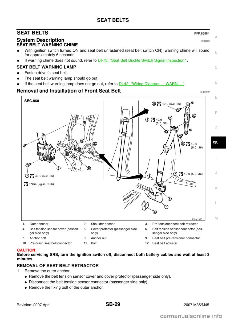
Removal and Installation of Front Seat Belt NHS0008J
CAUTION:
Before servicing SRS, turn the ignition switch off, disconnect both battery cables and wait at least 3
minutes.
REMOVAL OF SEAT BELT RETRACTOR
1. Remove the outer anchor.
�Remove the belt tension sensor cover and cover protector (passenger side only).
�Disconnect the belt tension sensor connector (passenger side only).
�Remove the fixing bolt of the outer anchor.
1. Outer anchor 2. Shoulder anchor 3. Pre-tensioner seat belt retractor
4. Belt tension sensor cover (passen-
ger side only)5. Cover protector (passenger side
only)6. Belt tension sensor connector (pas-
senger side only)
7. Anchor bolt 8. Anchor nut 9. Seat belt pre-tensioner connector
10. Pre-crash seat belt connector 11. Bolt 12. Seat belt adjuster
PHIA1106E
Page 4234 of 4647
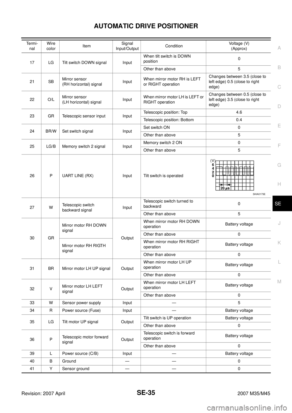
AUTOMATIC DRIVE POSITIONER
SE-35
C
D
E
F
G
H
J
K
L
MA
B
SE
Revision: 2007 April2007 M35/M45
17 LG Tilt switch DOWN signal InputWhen tilt switch is DOWN
position0
Other than above 5
21 SBMirror sensor
(RH horizontal) signalInputWhen mirror motor RH is LEFT
or RIGHT operationChanges between 3.5 (close to
left edge) 0.5 (close to right
edge)
22 O/LMirror sensor
(LH horizontal) signalInputWhen mirror motor LH is LEFT or
RIGHT operationChanges between 0.5 (close to
left edge) 3.5 (close to right
edge)
23 GR Telescopic sensor input InputTelescopic position: Top 4.6
Telescopic position: Bottom 0.4
24 BR/W Set switch signal InputSet switch ON 0
Other than above 5
25 LG/B Memory switch 2 signal InputMemory switch 2 ON 0
Other than above 5
26 P UART LINE (RX) Input Tilt switch is operated
27 WTelescopic switch
backward signalInputTelescopic switch turned to
backward0
Other than above 5
30 GRMirror motor RH DOWN
signal
OutputWhen mirror motor RH DOWN
operationBattery voltage
Other than above 0
Mirror motor RH RIGTH
signalWhen mirror motor RH RIGHT
operationBattery voltage
Other than above 0
31 BR Mirror motor LH UP signal OutputWhen mirror motor LH UP
operationBattery voltage
Other than above 0
32 VMirror motor LH LEFT
signalOutputWhen mirror motor LH LEFT
operationBattery voltage
Other than above 0
33 W Sensor power supply Input — 5
34 R Power source (Fuse) Input — Battery voltage
35 LG Tilt motor UP signal OutputTilt switch is UP operation Battery voltage
Other than above 0
36 PTelescopic motor forward
signalOutputTelescopic switch is forward
operationBattery voltage
Other than above 0
39 L Power source (C/B) Input — Battery voltage
40 B Ground — — 0
41 Y Sensor ground — — 0 Te r m i -
nal Wire
colorItemSignal
Input/OutputConditionVoltage (V)
(Approx)
SKIA0175E