Page 4280 of 4647
AUTOMATIC DRIVE POSITIONER
SE-81
C
D
E
F
G
H
J
K
L
MA
B
SE
Revision: 2007 April2007 M35/M45
Check Seat Memory and Set Switch Circuit NIS0026S
1. CHECK FUNCTION
With CONSULT-II
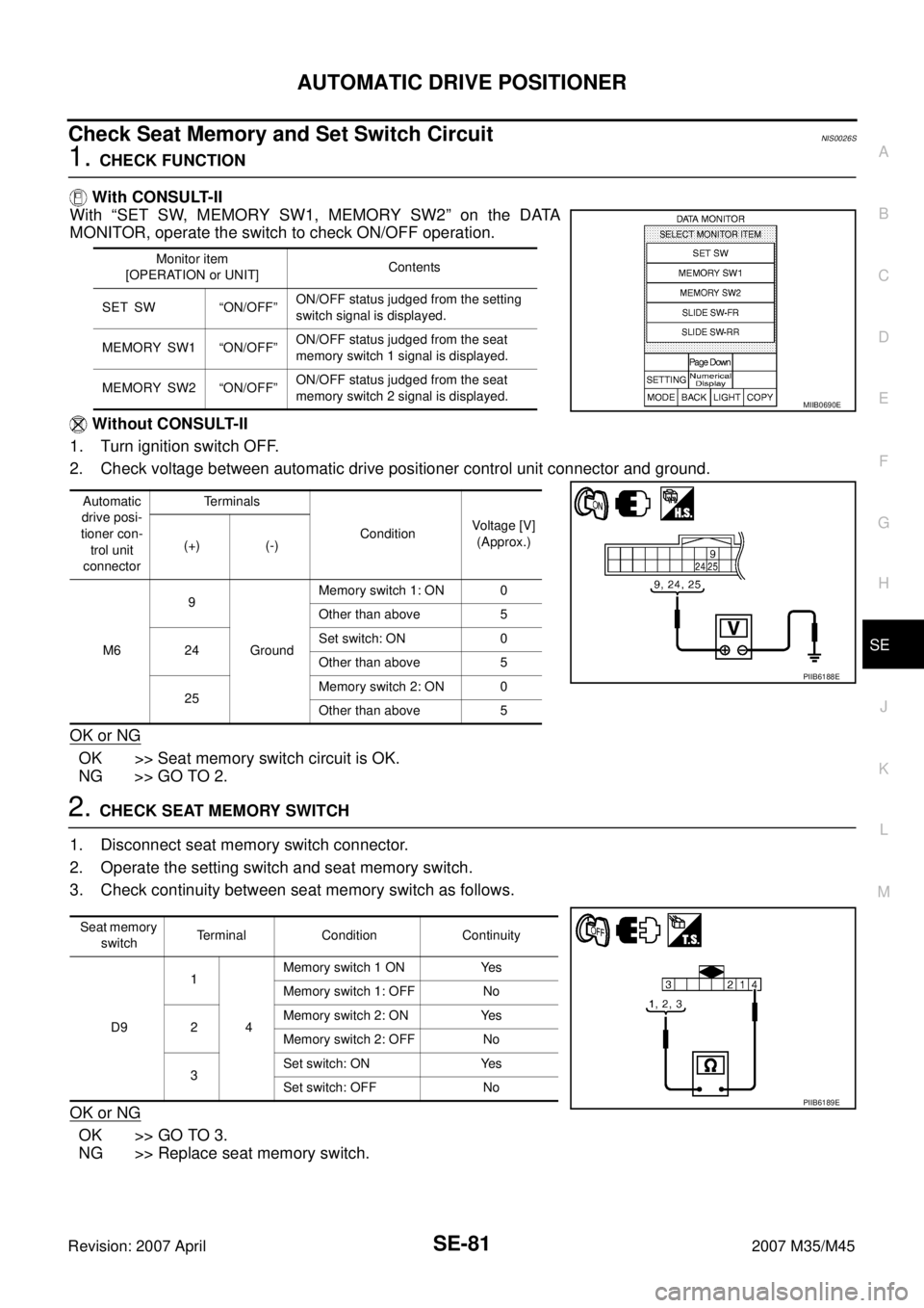
With “SET SW, MEMORY SW1, MEMORY SW2” on the DATA
MONITOR, operate the switch to check ON/OFF operation.
Without CONSULT-II
1. Turn ignition switch OFF.
2. Check voltage between automatic drive positioner control unit connector and ground.
OK or NG
OK >> Seat memory switch circuit is OK.
NG >> GO TO 2.
2. CHECK SEAT MEMORY SWITCH
1. Disconnect seat memory switch connector.
2. Operate the setting switch and seat memory switch.
3. Check continuity between seat memory switch as follows.
OK or NG
OK >> GO TO 3.
NG >> Replace seat memory switch.
Monitor item
[OPERATION or UNIT]Contents
SET SW “ON/OFF”ON/OFF status judged from the setting
switch signal is displayed.
MEMORY SW1 “ON/OFF”ON/OFF status judged from the seat
memory switch 1 signal is displayed.
MEMORY SW2 “ON/OFF”ON/OFF status judged from the seat
memory switch 2 signal is displayed.
Automatic
drive posi-
tioner con-
trol unit
connectorTerminals
ConditionVoltage [V]
(Approx.)
(+) (-)
M69
GroundMemory switch 1: ON 0
Other than above 5
24Set switch: ON 0
Other than above 5
25Memory switch 2: ON 0
Other than above 5
MIIB0690E
PIIB6188E
Seat memory
switchTerminal Condition Continuity
D91
4Memory switch 1 ON Yes
Memory switch 1: OFF No
2Memory switch 2: ON Yes
Memory switch 2: OFF No
3Set switch: ON Yes
Set switch: OFF No
PIIB6189E
Page 4283 of 4647
SE-84
AUTOMATIC DRIVE POSITIONER
Revision: 2007 April2007 M35/M45
4. CHECK SEAT MEMORY SWITCH INDICATOR SIGNAL
1. Connect seat memory switch connector.
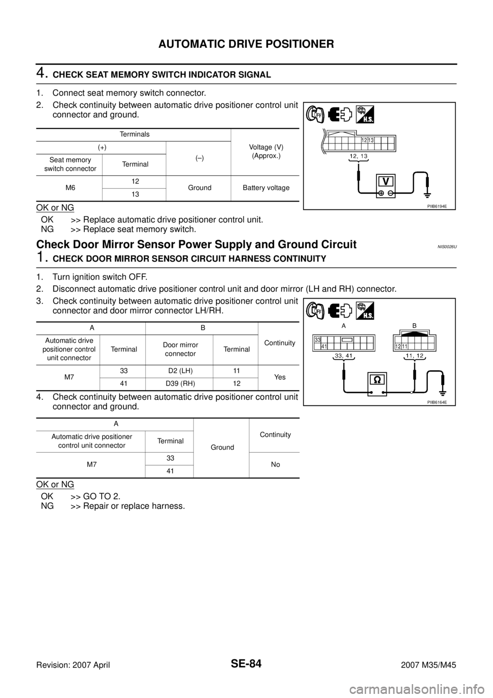
2. Check continuity between automatic drive positioner control unit
connector and ground.
OK or NG
OK >> Replace automatic drive positioner control unit.
NG >> Replace seat memory switch.
Check Door Mirror Sensor Power Supply and Ground Circuit NIS0026U
1. CHECK DOOR MIRROR SENSOR CIRCUIT HARNESS CONTINUITY
1. Turn ignition switch OFF.
2. Disconnect automatic drive positioner control unit and door mirror (LH and RH) connector.
3. Check continuity between automatic drive positioner control unit
connector and door mirror connector LH/RH.
4. Check continuity between automatic drive positioner control unit
connector and ground.
OK or NG
OK >> GO TO 2.
NG >> Repair or replace harness.
Terminals
Voltage (V)
(Approx.) (+)
(–)
Seat memory
switch connectorTerminal
M612
Ground Battery voltage
13
PIIB6194E
AB
Continuity Automatic drive
positioner control
unit connectorTe r m i n a lDoor mirror
connectorTerminal
M733 D2 (LH) 11
Ye s
41 D39 (RH) 12
A
GroundContinuity
Automatic drive positioner
control unit connectorTerminal
M733
No
41
PIIB6164E
Page 4285 of 4647
SE-86
AUTOMATIC DRIVE POSITIONER
Revision: 2007 April2007 M35/M45
Check A/T Device (Detention Switch) Circuit NIS0026V
1. CHECK FUNCTION
With CONSULT-II
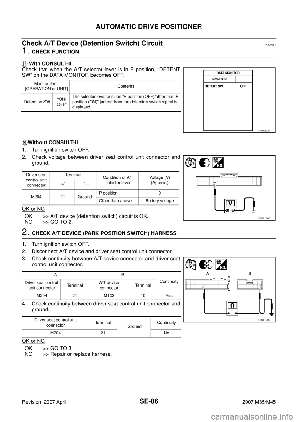
Check that when the A/T selector lever is in P position, “DETENT
SW” on the DATA MONITOR becomes OFF.
Without CONSULT-II
1. Turn ignition switch OFF.
2. Check voltage between driver seat control unit connector and
ground.
OK or NG
OK >> A/T device (detention switch) circuit is OK.
NG >> GO TO 2.
2. CHECK A/T DEVICE (PARK POSITION SWITCH) HARNESS
1. Turn ignition switch OFF.
2. Disconnect A/T device and driver seat control unit connector.
3. Check continuity between A/T device connector and driver seat
control unit connector.
4. Check continuity between driver seat control unit connector and
ground.
OK or NG
OK >> GO TO 3.
NG >> Repair or replace harness.
Monitor item
[OPERATION or UNIT]Contents
Detention SW“ON/
OFF”The selector lever position “P position (OFF)/other than P
position (ON)” judged from the detention switch signal is
displayed.
PIIB6293E
Driver seat
control unit
connectorTerminal
Condition of A/T
selector leverVoltage (V)
(Approx.)
(+) (–)
M204 21 GroundP position 0
Other than above Battery voltage
PIIB6198E
AB
Continuity
Driver seat control
unit connectorTe r m i n a lA/T device
connectorTerminal
M204 21 M133 10 Yes
Driver seat control unit
connectorTerminal
GroundContinuity
M204 21 No
PIIB6199E
Page 4286 of 4647

AUTOMATIC DRIVE POSITIONER
SE-87
C
D
E
F
G
H
J
K
L
MA
B
SE
Revision: 2007 April2007 M35/M45
3. CHECK PARK POSITION SWITCH
Check continuity between A/T device (detention switch) as follows.
OK or NG
OK >> Check the condition of the harness and the connector.
NG >> Replace A/T device.
Check Front Door Switch (Driver Side) Circuit NIS0026W
1. CHECK DOOR SWITCH INPUT SIGNAL
1. Turn ignition switch OFF.
2. Check voltage between BCM connector and ground.
OK or NG
OK >> Door switch circuit is OK.
NG >> GO TO 2.
2. CHECK HARNESS CONTINUITY
1. Turn ignition switch OFF.
2. Disconnect BCM and door switch (driver side) connector.
3. Check continuity between BCM connector and door switch (driver side) connector.
4. Check continuity between BCM connector ground.
OK or NG
OK >> GO TO 3.
NG >> Repair or replace harness.
A/T device Terminals Condition Continuity
M133 9 10P position Yes
Other than
P positionNo
PIIB6200E
Terminals
Door conditionVoltage (V)
(Approx.) (+)
(–)
BCM
connectorTerminal
M3 62 Ground Driver sideOPEN 0
CLOSE Battery voltage
PIIB6295E
AB
Continuity
BCM connector TerminalDoor switch
connectorTerminal
M3 62 B11 2 Yes
A
GroundContinuity
BCM connector Terminal
M3 62 No
PIIB6294E
Page 4287 of 4647
SE-88
AUTOMATIC DRIVE POSITIONER
Revision: 2007 April2007 M35/M45
3. CHECK DOOR SWITCH
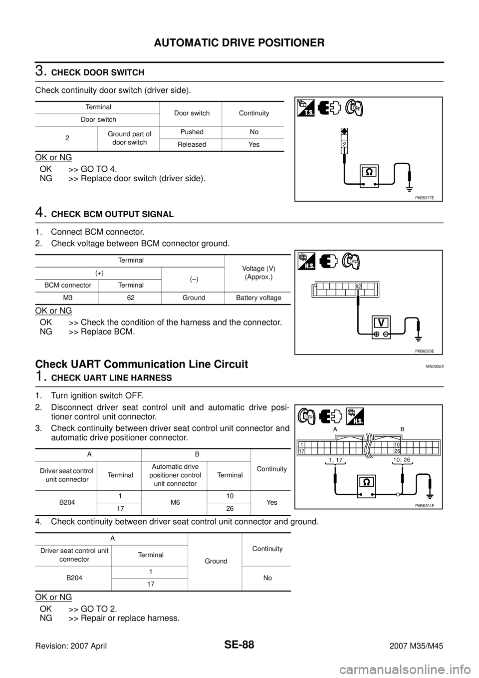
Check continuity door switch (driver side).
OK or NG
OK >> GO TO 4.
NG >> Replace door switch (driver side).
4. CHECK BCM OUTPUT SIGNAL
1. Connect BCM connector.
2. Check voltage between BCM connector ground.
OK or NG
OK >> Check the condition of the harness and the connector.
NG >> Replace BCM.
Check UART Communication Line Circuit NIS0026X
1. CHECK UART LINE HARNESS
1. Turn ignition switch OFF.
2. Disconnect driver seat control unit and automatic drive posi-
tioner control unit connector.
3. Check continuity between driver seat control unit connector and
automatic drive positioner connector.
4. Check continuity between driver seat control unit connector and ground.
OK or NG
OK >> GO TO 2.
NG >> Repair or replace harness.
Terminal
Door switch Continuity
Door switch
2Ground part of
door switchPushed No
Released Yes
PIIB5977E
Terminal
Voltage (V)
(Approx.) (+)
(–)
BCM connector Terminal
M3 62 Ground Battery voltage
PIIB6295E
AB
Continuity
Driver seat control
unit connectorTe r m i n a lAutomatic drive
positioner control
unit connectorTerminal
B2041
M610
Ye s
17 26
A
GroundContinuity
Driver seat control unit
connectorTerminal
B2041
No
17
PIIB6201E
Page 4288 of 4647
AUTOMATIC DRIVE POSITIONER
SE-89
C
D
E
F
G
H
J
K
L
MA
B
SE
Revision: 2007 April2007 M35/M45
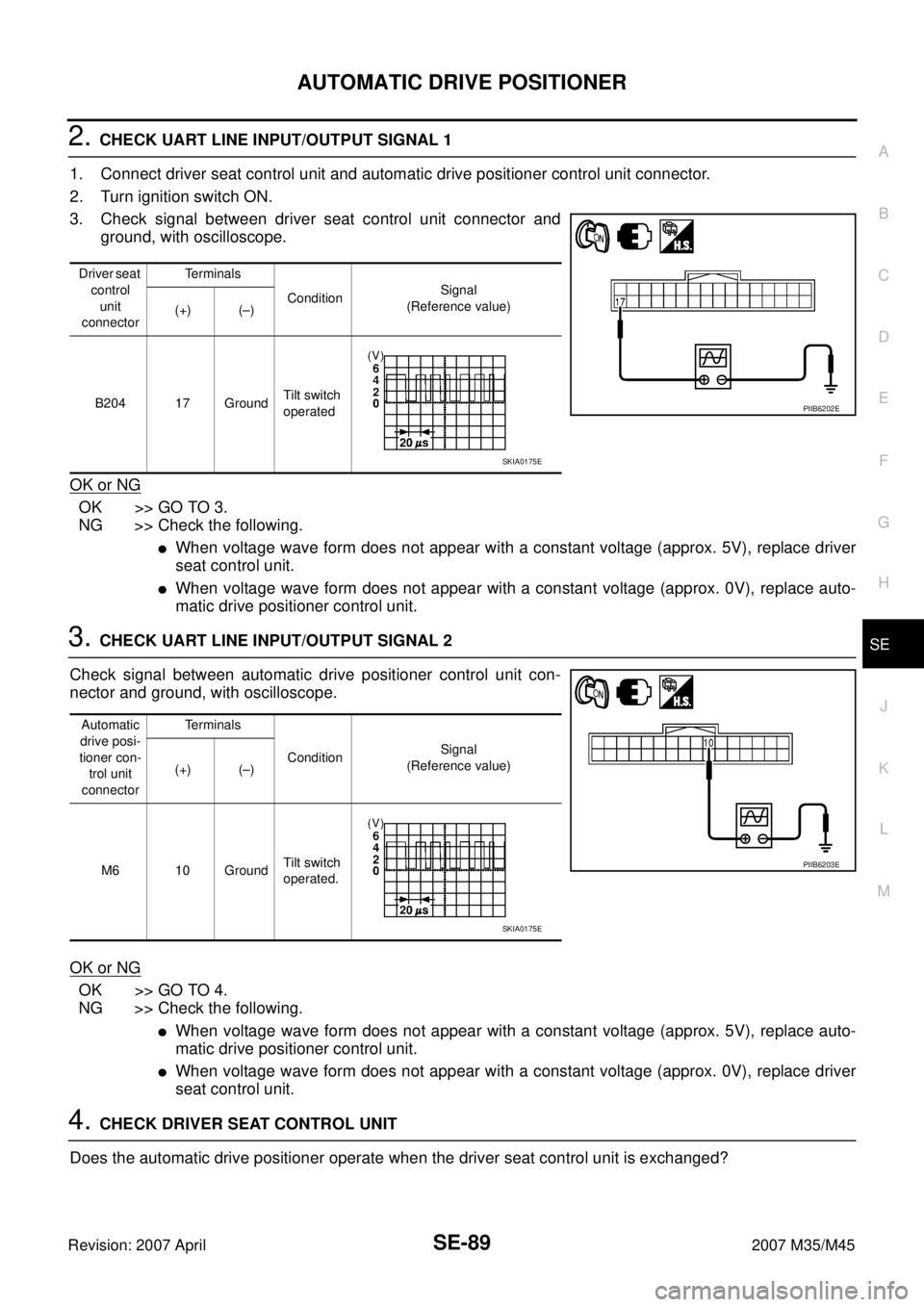
2. CHECK UART LINE INPUT/OUTPUT SIGNAL 1
1. Connect driver seat control unit and automatic drive positioner control unit connector.
2. Turn ignition switch ON.
3. Check signal between driver seat control unit connector and
ground, with oscilloscope.
OK or NG
OK >> GO TO 3.
NG >> Check the following.
�When voltage wave form does not appear with a constant voltage (approx. 5V), replace driver
seat control unit.
�When voltage wave form does not appear with a constant voltage (approx. 0V), replace auto-
matic drive positioner control unit.
3. CHECK UART LINE INPUT/OUTPUT SIGNAL 2
Check signal between automatic drive positioner control unit con-
nector and ground, with oscilloscope.
OK or NG
OK >> GO TO 4.
NG >> Check the following.
�When voltage wave form does not appear with a constant voltage (approx. 5V), replace auto-
matic drive positioner control unit.
�When voltage wave form does not appear with a constant voltage (approx. 0V), replace driver
seat control unit.
4. CHECK DRIVER SEAT CONTROL UNIT
Does the automatic drive positioner operate when the driver seat control unit is exchanged?
Driver seat
control
unit
connectorTe r m i n a l s
ConditionSignal
(Reference value)
(+) (–)
B204 17 GroundTilt switch
operated
PIIB6202E
SKIA0175E
Automatic
drive posi-
tioner con-
trol unit
connectorTe r m i n a l s
ConditionSignal
(Reference value)
(+) (–)
M6 10 GroundTilt switch
operated.
PIIB6203E
SKIA0175E
Page 4295 of 4647
SE-96
POWER SEAT(REAR)
Revision: 2007 April2007 M35/M45
POWER SEAT(REAR)PFP:88010
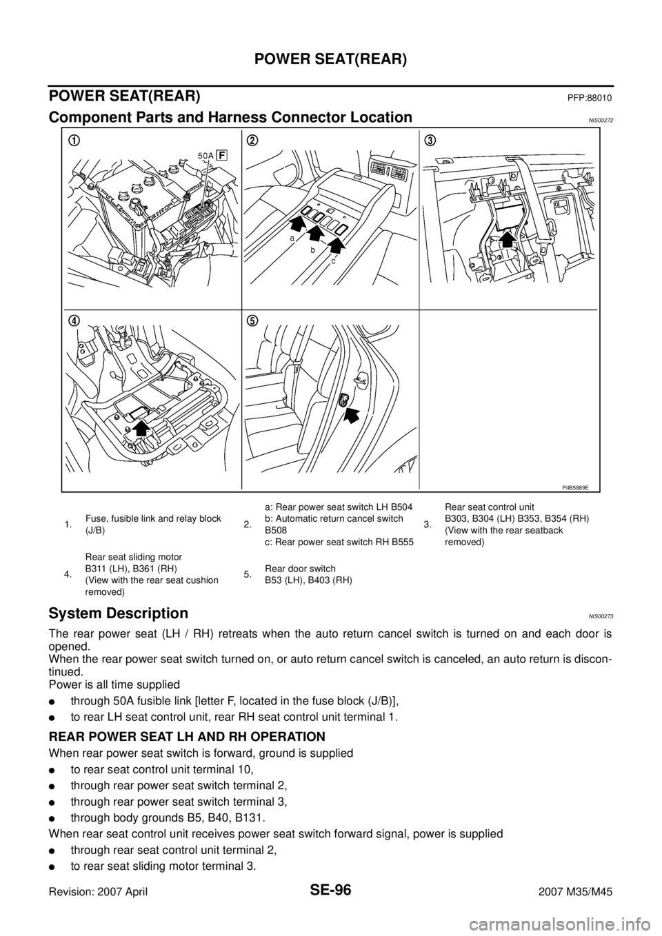
Component Parts and Harness Connector LocationNIS00272
System DescriptionNIS00273
The rear power seat (LH / RH) retreats when the auto return cancel switch is turned on and each door is
opened.
When the rear power seat switch turned on, or auto return cancel switch is canceled, an auto return is discon-
tinued.
Power is all time supplied
�through 50A fusible link [letter F, located in the fuse block (J/B)],
�to rear LH seat control unit, rear RH seat control unit terminal 1.
REAR POWER SEAT LH AND RH OPERATION
When rear power seat switch is forward, ground is supplied
�to rear seat control unit terminal 10,
�through rear power seat switch terminal 2,
�through rear power seat switch terminal 3,
�through body grounds B5, B40, B131.
When rear seat control unit receives power seat switch forward signal, power is supplied
�through rear seat control unit terminal 2,
�to rear seat sliding motor terminal 3.
PIIB5889E
1.Fuse, fusible link and relay block
(J/B)2.a: Rear power seat switch LH B504
b: Automatic return cancel switch
B508
c: Rear power seat switch RH B5553.Rear seat control unit
B303, B304 (LH) B353, B354 (RH)
(View with the rear seatback
removed)
4.Rear seat sliding motor
B311 (LH), B361 (RH)
(View with the rear seat cushion
removed)5.Rear door switch
B53 (LH), B403 (RH)
Page 4296 of 4647

POWER SEAT(REAR)
SE-97
C
D
E
F
G
H
J
K
L
MA
B
SE
Revision: 2007 April2007 M35/M45
Then ground is supplied
�through rear seat sliding motor terminals 5,
�through body grounds B5, B40, B131.
When power and ground are supplied, rear power seat slide moves forward.
When rear power seat switch is backward, ground is supplied
�to rear seat control unit terminal 15,
�through rear power seat switch terminal 1,
�through rear power seat switch terminal 3,
�through body grounds B5, B40, B131.
When rear seat control unit receives power seat switch backward signal, power is supplied
�to rear seat control unit terminal 7,
�through rear seat sliding motor terminal 4.
Then ground is supplied
�through rear seat sliding motor terminals 5,
�through body grounds B5, B40, B131.
When power and ground are supplied, rear power seat slide moves backward.
REAR SEAT RETREAT FUNCTION
When rear door open, ground is supplied
�to rear seat control unit terminal 16,
�through rear door switch terminal 2,
When rear seat control unit receives automatic return cancel switch ON and rear door switch open signal,
power is supplied
�through rear seat control unit terminal 7,
�to rear seat sliding motor terminal 4.
Then ground is supplied
�through rear seat sliding motor terminals 5,
�through body grounds B5, B40, B131.
When power and ground are supplied, rear power seat slide moves backward.
When rear seat sliding motor is operated, ground is supplied
�to rear seat control unit terminal 12,
�through rear seat sliding motor terminal 1,
�through rear seat sliding motor terminal 2,
�through rear seat control unit terminal 19,
�through rear seat control unit terminals 13,
�through body grounds B5, B40, B131.
Then rear seat control unit receives rear power seat sliding sensor signal.
The rear power seat control unit controls the seat position of the system operation with the signal.