2006 TOYOTA RAV4 injector
[x] Cancel search: injectorPage 1935 of 2000

2AZ-FE ENGINE CONTROL SYSTEM – SFI SYSTEMES–47
ES
DATA LIST / ACTIVE TEST
1. DATA LIST
HINT:
By reading the DATA LIST displayed on an intelligent
tester, values can be checked, including those of the
switches, sensors, and actuators, without removing any
parts. Reading the DATA LIST as the first step of
troubleshooting is one method of shortening diagnostic
time.
NOTICE:
In the table below, the values listed under Normal
Condition are for reference only. Do not depend
solely on these values when determining whether or
not a part is faulty.
(a) Warm up the engine.
(b) Turn the ignition switch OFF.
(c) Connect the intelligent tester to the DLC3.
(d) Turn the ignition switch ON.
(e) Turn the tester ON.
(f) Select the following menu items: DIAGNOSIS /
ENHANCED OBD II / DATA LIST.
(g) Check the values by referring to the table below.
ECM:
Intelligent Tester Display Measurement: Range (Display) Normal Condition*1 Diagnostic Note
INJECTORInjection period of No. 1 cylinder:
Min.: 0 ms, Max.: 32.64 ms1.0 to 3.0 ms: Idling -
IGN ADVANCE Ignition timing advance for No. 1
cylinder:
Min.: -64 deg, Max.: 63.5 degBTDC 0 to 14 deg: Idling -
CALC LOADCalculated load by ECM:
Min.: 0 %, Max.: 100 %• 10 to 30 %: Idling
• 10 to 30 %: Running without
load at 2,500 rpmLoad value
VEHICLE LOADVehicle load:
Min.: 0 %, Max.: 25,700 %Actual vehicle loadLoad percentage in terms of
maximum intake air flow amount
MAFAir flow rate from Mass Air Flow
(MAF) meter:
Min.: 0 g/sec., Max.: 655.35 g/sec.1 to 3 g/sec.: Idling
2 to 6 g/sec.: Running without
load at 2,500 rpmIf value approximately 0.0 g/sec.:
• MAF meter power source
circuit open
• VG circuit open or short
If value 160.0 g/sec. or more:
• E2G circuit open
ENGINE SPDEngine speed:
Min.: 0 rpm, Max.: 16,383.75 rpm650 to 750 rpm: Idling -
VEHICLE SPDVehicle speed:
Min.: 0 km/h, Max.: 255 km/hActual vehicle speed Speed indicated on speedometer
COOLANT TEMPEngine coolant temperature:
Min.: -40
C, Max.: 140C80 to 100C (176 to 212F):
After warming up• If -40
C (-40F): sensor circuit
open
• If 140
C (284F) or more:
sensor circuit shorted
INTAKE AIRIntake air temperature:
Min.: -40
C, Max.: 140CEquivalent to ambient air
temperature• If -40
C (-40F): sensor circuit
open
• If 140
C (284F) or more:
sensor circuit shorted
AIR-FUEL RATIORatio compared to stoichiometric
level:
Min.: 0, Max.: 1.9990.8 to 1.2: Idling• Less than 1 (0 to 0.999) =
Lean
• Stoichiometric air-fuel ratio = 1
• Greater than 1 (1.001 to
1.999) = Rich
Page 1943 of 2000

2AZ-FE ENGINE CONTROL SYSTEM – SFI SYSTEMES–55
ES
(c) Turn the tester ON.
(d) Select the following menu items: DIAGNOSIS /
ENHANCED OBD II / ACTIVE TEST.
(e) Perform the ACTIVE TEST by referring to the table
below.
ECM:
Intelligent Tester Displays Test Details Control Ranges Diagnostic Notes
INJ VOL Change injection volume Between -12.5 and 24.8 %• All injectors tested at same
time
• Perform test at less than
3,000 rpm
• Injection volume can be
changed in 0.1 % graduations
within control range
A/F CONTROL Change injection volumeDecrease by 12.5 % or increase
by 24.8 %• Perform test at less than
3,000 rpm
• A/F CONTROL enables
checking and graphing of A/F
(Air-Fuel Ratio) sensor and
Heated Oxygen (HO2) sensor
voltage outputs
• To conduct test, select
following menu items:
ACTIVE TEST / A/F
CONTROL / USER DATA /
AFS B1S1 and O2S B1S2;
then press YES and ENTER
followed by F4.
EVAP VSV (ALONE) Activate purge VSV control ON/OFF -
VVT B1 Control VVT (bank 1)-128 to 127 %
This value added to present OCV
control duty
100 %: Maximum advance
-100 %: Maximum retardEngine stall or rough idle when
VVT actuator operated by 100 %.
Test possible while vehicle
stopped and engine idling
VVT CTRL B1Turn on and off OCV
(Oil Control Valve)ON/OFF• Engine stalls or idles roughly
when OCV turned ON
• Normal engine running or
idling when OCV OFF
• Test possible while vehicle
stopped and engine idling
FUEL PUMP / SPDActivate fuel pump (C/OPN
Relay)ON/OFFTest possible when engine
stopped
TC/TE1Turn on and off TC and TE1
connectionON/OFF• ON: TC and TE1 connected
• OFF: TC and TE1
disconnected
FC IDL PROHBT Prohibit idling fuel cut control ON/OFF -
COOLING FAN Control electric cooling fan ON/OFF -
ETCS OPEN SLOW Throttle actuator ON: Throttle valve opens slowly Test possible when following
conditions met:
• Engine stopped
• Shift position in P
• Fully depressing accelerator
pedal (APP: 59
or more) ETCS CLOSE SLOW Throttle actuator ON: Throttle valve closes slowly
ETCS OPEN FAST Throttle actuator ON: Throttle valve opens fast
ETCS CLOSE FAST Throttle actuator ON: Throttle valve closes fast
FUEL CUT #1 Cylinder #1 injector fuel cut ON/OFF
Test possible during vehicle
stopping and engine idling
ON: All cylinder injector fuel cut
and ignition stop FUEL CUT #2 Cylinder #2 injector fuel cut ON/OFF
FUEL CUT #3 Cylinder #3 injector fuel cut ON/OFF
FUEL CUT #4 Cylinder #4 injector fuel cut ON/OFF
FUEL CUT ALL All cylinder injector fuel cut ON/OFF ON: All cylinder injector fuel cut
VACUUM PUMP Leak detection pump ON/OFF -
VENT VALVE Vent valve ON/OFF -
Page 1944 of 2000

ES–562AZ-FE ENGINE CONTROL SYSTEM – SFI SYSTEM
ES
HINT:
*: When cranking the engine, each cylinder measures the
engine rpm.
In this ACTIVE TEST, the fuel and ignition of all cylinders is
cut, and cranking occurs for approximately 10 seconds. Then,
each cylinder measures the engine rpm. If a cylinder's engine
rpm is higher than the others, that cylinder's compression
pressure is compared to the others, and whether or not the
compression pressure is low can be determined.
1. Warm up the engine.
2. Turn the ignition switch OFF.
3. Connect the intelligent tester to the DLC3.
4. Turn the ignition switch ON and turn the intelligent tester
ON.
5. Select the following menu items: DIAGNOSIS /
ENHANCED OBD II / ACTIVE TEST / COMPRESS
CHECK.
HINT:
If the results are not displayed normally, select the display
items from the DATA LIST before performing the ACTIVE
TEST. Select the following menu items: DIAGNOSIS /
ENHANCED OBD II / DATA LIST / USER DATA / ENG
SPEED #1 and ENG SPEED #2, ENG SPEED #3, ENG
SPEED #4 (Press the YES button to change the ENG
SPEED #1 to #4 is YES) and then press the ENTER
button.
6. While the engine is not running, press the RIGHT or LEFT
button to change the COMPRESS CHECK to ON.
HINT:
After performing the above procedure, the ACTIVE TEST's
COMPRESS CHECK will start. Fuel injection for all
cylinders is prohibited, and the each cylinder's engine rpm
measurement will enter standby.
7. Fully open the throttle.
8. Crank the engine for about 10 seconds.
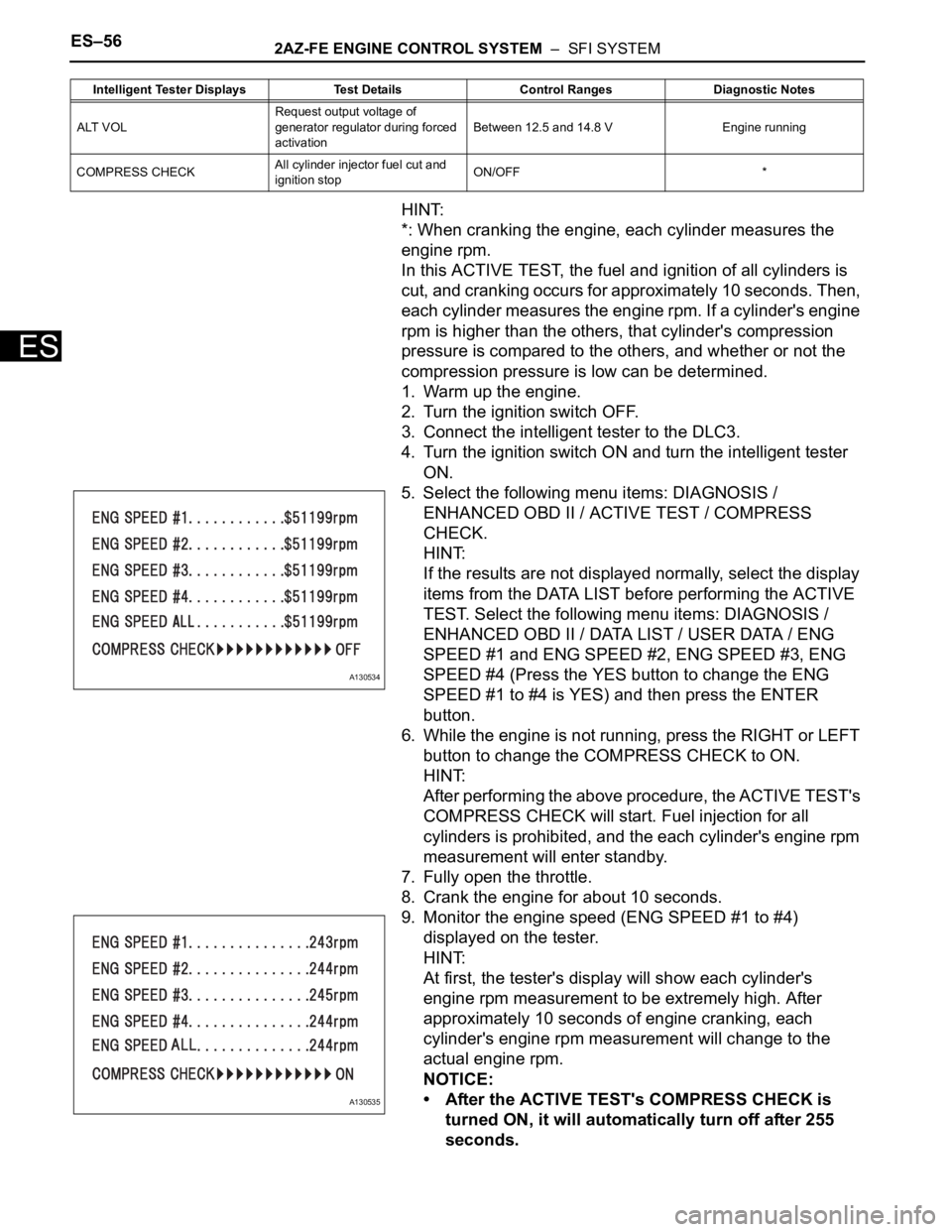
9. Monitor the engine speed (ENG SPEED #1 to #4)
displayed on the tester.
HINT:
At first, the tester's display will show each cylinder's
engine rpm measurement to be extremely high. After
approximately 10 seconds of engine cranking, each
cylinder's engine rpm measurement will change to the
actual engine rpm.
NOTICE:
• After the ACTIVE TEST's COMPRESS CHECK is
turned ON, it will automatically turn off after 255
seconds.
ALT VOLRequest output voltage of
generator regulator during forced
activationBetween 12.5 and 14.8 V Engine running
COMPRESS CHECKAll cylinder injector fuel cut and
ignition stopON/OFF * Intelligent Tester Displays Test Details Control Ranges Diagnostic Notes
A130534
A130535
Page 1949 of 2000

2AZ-FE ENGINE CONTROL SYSTEM – SFI SYSTEMES–61
ES
P0171 System Too Lean
(Bank 1)- Air induction system
- Injector blockage
- MAF meter
- ECT sensor
- Fuel pressure
- Gas leakage from
exhaust system
- Open or short in A/F
sensor (sensor 1)
circuit
- A/F sensor (sensor
1)
- A/F sensor heater
(sensor 1)
- Integration relay
(EFI MAIN relay)
- A/F sensor heater
and EFI MAIN relay
circuits
- PCV hose
connections
- PCV valve and hose
- ECMComes on DTC storedES-147
P0172 System Too Rich
(Bank 1)- Injector leakage or
blockage
- MAF meter
- ECT sensor
- Ignition system
- Fuel pressure
- Gas leakage from
exhaust system
- Open or short in A/F
sensor (sensor 1)
circuit
- A/F sensor (sensor
1)
- A/F sensor heater
(sensor 1)
- Integration relay
(EFI MAIN relay)
- A/F sensor heater
and EFI MAIN relay
circuits
- ECMComes on DTC storedES-147
P0220 Throttle / Pedal
Position Sensor /
Switch "B" Circuit- TP sensor (built into
throttle body)
- ECMComes on DTC storedES-114
P0222 Throttle / Pedal
Position Sensor /
Switch "B" Circuit
Low Input- TP sensor (built into
throttle body)
- Short in VTA2 circuit
- Open in VC circuit
- ECMComes on DTC storedES-114
P0223 Throttle / Pedal
Position Sensor /
Switch "B" Circuit
High Input- TP sensor (built into
throttle body)
- Open in VTA2 circuit
- Open in E2 circuit
- Short between VC
and VTA2 circuits
- ECMComes on DTC storedES-114 DTC No. Detection Item Trouble Areas MIL Memory See page
Page 1950 of 2000

ES–622AZ-FE ENGINE CONTROL SYSTEM – SFI SYSTEM
ES
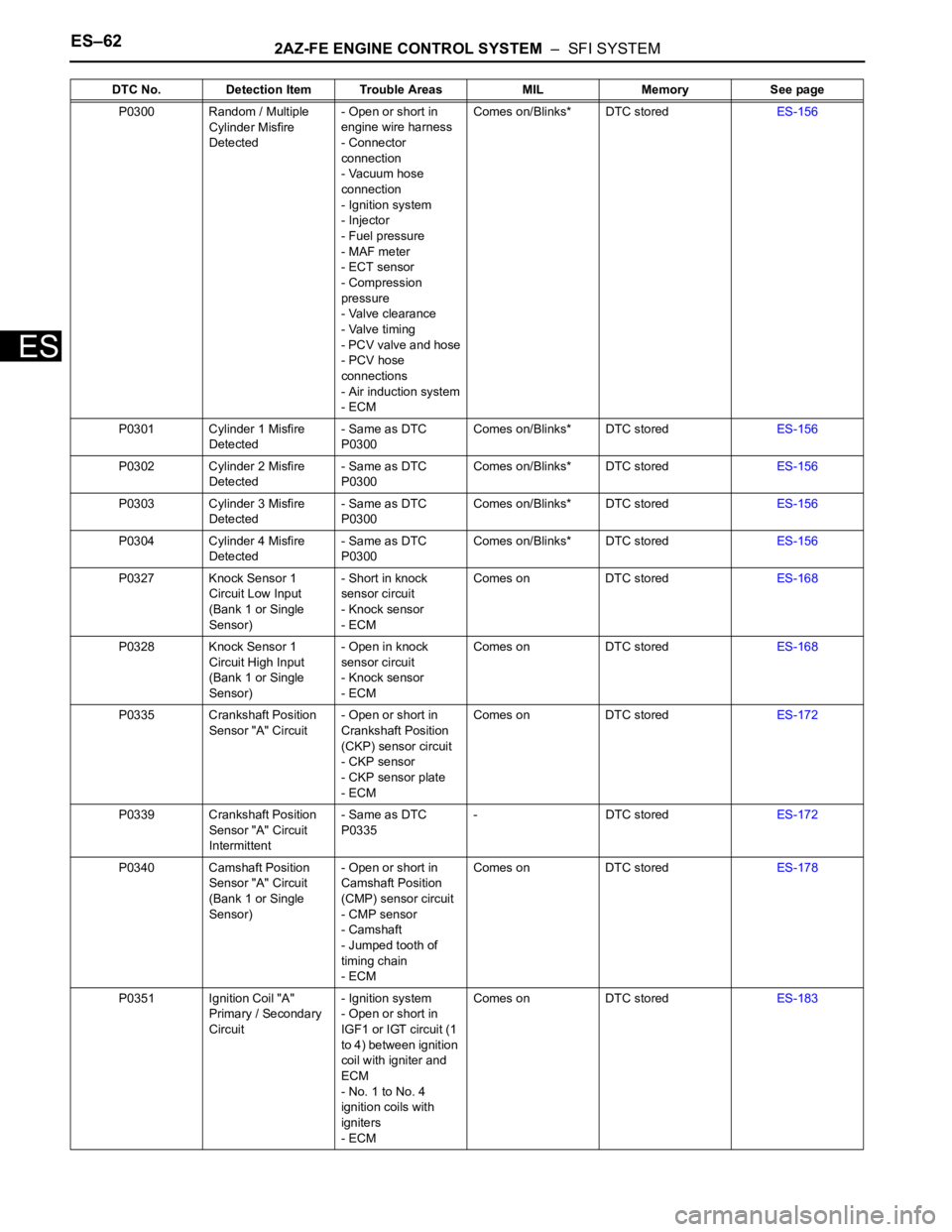
P0300 Random / Multiple
Cylinder Misfire
Detected- Open or short in
engine wire harness
- Connector
connection
- Vacuum hose
connection
- Ignition system
- Injector
- Fuel pressure
- MAF meter
- ECT sensor
- Compression
pressure
- Valve clearance
- Valve timing
- PCV valve and hose
- PCV hose
connections
- Air induction system
- ECMComes on/Blinks* DTC storedES-156
P0301 Cylinder 1 Misfire
Detected- Same as DTC
P0300Comes on/Blinks* DTC storedES-156
P0302 Cylinder 2 Misfire
Detected- Same as DTC
P0300Comes on/Blinks* DTC storedES-156
P0303 Cylinder 3 Misfire
Detected- Same as DTC
P0300Comes on/Blinks* DTC storedES-156
P0304 Cylinder 4 Misfire
Detected- Same as DTC
P0300Comes on/Blinks* DTC storedES-156
P0327 Knock Sensor 1
Circuit Low Input
(Bank 1 or Single
Sensor)- Short in knock
sensor circuit
- Knock sensor
- ECMComes on DTC storedES-168
P0328 Knock Sensor 1
Circuit High Input
(Bank 1 or Single
Sensor)- Open in knock
sensor circuit
- Knock sensor
- ECMComes on DTC storedES-168
P0335 Crankshaft Position
Sensor "A" Circuit- Open or short in
Crankshaft Position
(CKP) sensor circuit
- CKP sensor
- CKP sensor plate
- ECMComes on DTC storedES-172
P0339 Crankshaft Position
Sensor "A" Circuit
Intermittent- Same as DTC
P0335- DTC storedES-172
P0340 Camshaft Position
Sensor "A" Circuit
(Bank 1 or Single
Sensor)- Open or short in
Camshaft Position
(CMP) sensor circuit
- CMP sensor
- Camshaft
- Jumped tooth of
timing chain
- ECMComes on DTC storedES-178
P0351 Ignition Coil "A"
Primary / Secondary
Circuit- Ignition system
- Open or short in
IGF1 or IGT circuit (1
to 4) between ignition
coil with igniter and
ECM
- No. 1 to No. 4
ignition coils with
igniters
- ECMComes on DTC storedES-183 DTC No. Detection Item Trouble Areas MIL Memory See page