2006 TOYOTA RAV4 injector
[x] Cancel search: injectorPage 556 of 2000

ES–322GR-FE ENGINE CONTROL SYSTEM – SFI SYSTEM
ES
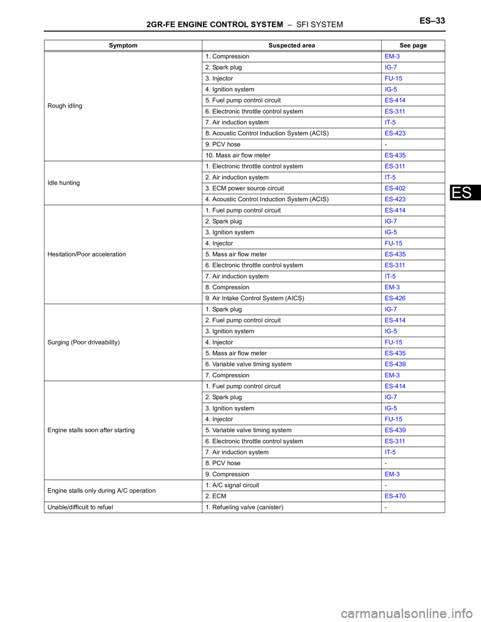
PROBLEM SYMPTOMS TABLE
HINT:
Use the table below to help determine the cause of the
problem symptom. The potential causes of the symptoms are
listed in order of probability in the "Suspected area" column of
the table. Check each symptom by checking the suspected
areas in the order they are listed. Replace parts as
necessary.
Symptom Suspected area See page
Engine does not crank (Does not start)1. BatteryCH-5
2. StarterST-8
3. Starter relayST-16
4. Park/neutral position switchAX-132
5. Immobiliser systemEI-3
No initial combustion (Does not start)1. ECM power source circuitES-402
2. Crankshaft position sensorES-448
3. VVT sensorES-214
4. Ignition systemIG-5
5. Fuel pump control circuitES-414
6. ECMES-470
7. VC output circuitES-408
Engine cranks normally but difficult to start1. Fuel pump control circuitES-414
2. CompressionEM-3
Difficult to start with cold engine1. Ignition systemIG-5
2. Spark plugIG-7
3. Fuel pump control circuitES-414
4. InjectorFU-15
Difficult to start with warm engine1. InjectorFU-15
2. Ignition systemIG-5
3. Spark plugIG-7
4. Fuel pump control circuitES-414
High engine idle speed1. Electronic throttle control systemES-311
2. A/C signal circuit -
3. ECM power source circuitES-402
4. Acoustic Control Induction System (ACIS)ES-423
Low engine idle speed (Poor idling)1. Electronic throttle control systemES-311
2. A/C signal circuit -
3. Fuel pump control circuitES-414
4. Air induction systemIT-5
5. Acoustic Control Induction System (ACIS)ES-423
6. PCV hose -
Page 557 of 2000

2GR-FE ENGINE CONTROL SYSTEM – SFI SYSTEMES–33
ES
Rough idling1. CompressionEM-3
2. Spark plugIG-7
3. InjectorFU-15
4. Ignition systemIG-5
5. Fuel pump control circuitES-414
6. Electronic throttle control systemES-311
7. Air induction systemIT-5
8. Acoustic Control Induction System (ACIS)ES-423
9. PCV hose -
10. Mass air flow meterES-435
Idle hunting1. Electronic throttle control systemES-311
2. Air induction systemIT-5
3. ECM power source circuitES-402
4. Acoustic Control Induction System (ACIS)ES-423
Hesitation/Poor acceleration1. Fuel pump control circuitES-414
2. Spark plugIG-7
3. Ignition systemIG-5
4. InjectorFU-15
5. Mass air flow meterES-435
6. Electronic throttle control systemES-311
7. Air induction systemIT-5
8. CompressionEM-3
9. Air Intake Control System (AICS)ES-426
Surging (Poor driveability)1. Spark plugIG-7
2. Fuel pump control circuitES-414
3. Ignition systemIG-5
4. InjectorFU-15
5. Mass air flow meterES-435
6. Variable valve timing systemES-439
7. CompressionEM-3
Engine stalls soon after starting1. Fuel pump control circuitES-414
2. Spark plugIG-7
3. Ignition systemIG-5
4. InjectorFU-15
5. Variable valve timing systemES-439
6. Electronic throttle control systemES-311
7. Air induction systemIT-5
8. PCV hose -
9. CompressionEM-3
Engine stalls only during A/C operation1. A/C signal circuit -
2. ECMES-470
Unable/difficult to refuel 1. Refueling valve (canister) -Symptom Suspected area See page
Page 559 of 2000

2GR-FE ENGINE CONTROL SYSTEM – SFI SYSTEMES–35
ES
THW (B30-79) - ETHW (B30-78) L - BR Engine coolant
temperature sensorIdling, Engine coolant temperature
80
C (176F)0.2 to 1.0 V
VCTA (B30-96) - ETA (B30-97) B - W Power source of throttle
position sensor (specific
voltage)Ignition switch ON 4.5 to 5.5 V
VTA1 (B30-98) - ETA (B30-97) Y - W Throttle position sensor
(for engine control)Ignition switch ON,
Throttle valve fully closed0.5 to 1.1 V
Ignition switch ON,
Throttle valve fully open3.3 to 4.9 V
VTA2 (B30-99) - ETA (B30-97) GR - W Throttle position sensor
(for sensor malfunction
detection)Ignition switch ON,
Throttle valve fully closed2.1 to 3.1 V
Ignition switch ON,
Throttle valve fully open4.6 to 5.0 V
VPA (A9-55) - EPA (A9-59) W - Y Accelerator pedal position
sensor (for engine control)Ignition switch ON,
Accelerator pedal released0.5 to 1.1 V
Ignition switch ON,
Accelerator pedal fully depressed2.6 to 4.5 V
VPA2 (A9-56) - EPA2 (A9-60) R - O Accelerator pedal position
sensor (for sensor
malfunctioning detection)Ignition switch ON,
Accelerator pedal released1.2 to 2.0 V
Ignition switch ON,
Accelerator pedal fully depressed3.4 to 5.0 V
VCPA (A9-57) - EPA (A9-59) B - Y Power source of
accelerator pedal position
sensor (for VPA)Ignition switch ON 4.5 to 5.5 V
VCP2 (A9-58) - EPA2 (A9-60) L - O Power source of
accelerator pedal position
sensor (for VPA2)Ignition switch ON 4.5 to 5.5 V
HA1A (B30-86) - E04 (B30-23)
HA2A (B30-109) - E04 (B30-23) G - BR
B - BRA/F sensor heater Idling Below 3.0 V
Ignition switch ON 9 to 14 V
A1A+ (B30-93) - E1 (B30-81) W -BR A/F sensor Ignition switch ON 3.3 V*
A1A- (B30-116) - E1 (B30-81) BR - BR A/F sensor Ignition switch ON3.0 V*
A2A+ (B30-120) - E1 (B30-81) L - BR A/F sensor Ignition switch ON 3.3 V*
A2A- (B30-119) - E1 (B30-81) Y - BR A/F sensor Ignition switch ON 3.0 V*
HT1B (B30-48) - E03 (B30-104)
HT2B (B30-47) - E03 (B30-104)LG - BR
Y - BRHeated oxygen sensor
heaterIdling Below 3.0 V
Ignition switch ON 9 to 14 V
OX1B (B30-88) - EX1B (B30-65)
OX2B (B30-87) - EX2B- (B30-64)W - GR
B - B-WHeated oxygen sensor Engine speed maintained at 2,500
rpm for 2 minutes after warming up
sensorPulse generation (see
waveform 2)
#10 (B30-45) - E01 (B30-22)
#20 (B30-85) - E01 (B30-22)
#30 (B30-44) - E01 (B30-22)
#40 (B30-84) - E01 (B30-22)
#50 (B30-43) - E01 (B30-22)
#60 (B30-83) - E01 (B30-22)Y - BR
W - BR
B - BR
BR - BR
L - BR
G - BRInjector Ignition switch ON 9 to 14 V
Idling Pulse generation (see
waveform 3)
KNK1 (B30-95) - EKNK (B30-94)
KNK2 (B30-118) - EKN2 (B30-
11 7 )R - G
B - WKnock sensor Engine speed maintained at 4,000
rpm after warming up enginePulse generation (see
waveform 4)
VCV1 (B30-115) - E1 (B30-81) G-R - BR Power source for VVT
sensor (specific voltage)Ignition switch ON 4.5 to 5.0 V
VCV2 (B30-113) - E1 (B30-81) V - BR Power source for VVT
sensor (specific voltage)Ignition switch ON 4.5 to 5.0 V
VCE1 (B30-114) - E1 (B30-81) GR - BR Power source for VVT
sensor specific voltage)Ignition switch ON 4.5 to 5.0 V
VCE2 (B30-112) - E1 (B30-81) Y - BR Power source for VVT
sensor (specific voltage)Ignition switch ON 4.5 to 5.0 V
VV1+ (B30-69) - VV1- (B30-92) P - L-B Variable valve timing
(VVT) sensor (Intake side
(bank 1))Idling Pulse generation
(see waveform 5) Symbol (Terminal No.) Wiring Color Terminal Description Condition Specified Condition
Page 562 of 2000

ES–382GR-FE ENGINE CONTROL SYSTEM – SFI SYSTEM
ES
(c) WAVEFORM 2
Heated oxygen sensor
HINT:
In DATA LIST, item O2S B1 S2 shows the ECM
input values from the heated oxygen sensor.
(d) WAVEFORM 3
Injector No. 1 (to No. 4) injection signal
HINT:
The wavelength becomes shorter as the engine rpm
increases.
(e) WAVEFORM 4
Knock sensor
HINT:
• The wavelength becomes shorter as the engine
rpm increases.
• The waveforms and amplitudes displayed differ
slightly depending on the vehicle.
(f) WAVEFORM 5
Crankshaft position sensor and Camshaft
position sensor
HINT:
The wavelength becomes shorter as the engine rpm
increases.
A088863E05
Symbol (Terminal No.) Between OX1B and EX1B
Between OX2B and EX2B
Tester Range 0.2 V/DIV., 200 msec./DIV.
Condition Engine speed maintained at 2,500 rpm
for 2 minutes after warming up sensor
A093279E04
Symbol (Terminal No.) Between #10 (to #60) and E01
Tester Range 20 V/DIV., 20 msec./DIV.
Condition Idling
A085286E03
Symbol (Terminal No.) Between KNK1 and EKNK
Between KNK2 and EKN2
Tester Range 1 V/DIV., 1 msec./DIV.
Condition Engine speed maintained at 4,000 rpm
after warming up engine
A122767E04
Symbol (Terminal No.) Between NE+ and NE-
Between VV1+ and VV1-
Between EV1+ and EV1-
Between VV2+ and VV2-
Between EV2+ and EV2-
Tester Range 5 V/DIV., 20 msec./DIV.
Condition Idling
Page 570 of 2000

ES–462GR-FE ENGINE CONTROL SYSTEM – SFI SYSTEM
ES
FREEZE FRAME DATA
1. DESCRIPTION
Freeze frame data records the engine conditions (fuel
system, calculated load, engine coolant temperature,
fuel trim, engine speed, vehicle speed, etc.) when a
malfunction is detected. When troubleshooting, it can
help determine if the vehicle was running or stopped, the
engine was warmed up or not, the air-fuel ratio was Lean
or Rich, and other data from the time the malfunction
occurred.
HINT:
If it is impossible to duplicate the problem even though a
DTC is detected, confirm the freeze frame data.
The ECM records engine conditions in the form of freeze
frame data every 0.5 seconds. Using the intelligent
tester, 5 separate sets of freeze frame data can be
checked.
– 3 data sets before the DTC was set.
– 1 data set when the DTC was set.
– 1 data set after the DTC was set.
These data sets can be used to simulate the condition
of the vehicle around the time of the occurrence of the
malfunction. The data may assist in identifying the
cause of the malfunction, and in judging whether it
was temporary or not.
2. LIST OF FREEZE FRAME DATA
A103809E11
LABEL
(Intelligent Tester Display)Measurement Item Diagnostic Note
INJECTOR Injection period of No. 1 cylinder -
IGN ADVANCE Ignition advance -
CALC LOAD Calculated load Calculated load by ECM
VEHICLE LOAD Vehicle load -
MAF Mass air flow volumeIf approximately 0.0 g/sec.:
• Mass air flow meter power source circuit
open or short
• VG circuit open or short
If 160.0 g/sec. or more:
• E2G circuit open
ENGINE SPD Engine speed -
VEHICLE SPD Vehicle speed Speed indicated on speedometer
COOLANT TEMP Engine coolant temperatureIf -40
C (-40F), sensor circuit open
If 140
C (284F) or more, sensor circuit
shorted
INTAKE AIR Intake air temperature If -40
C (-40F), sensor circuit open
If 140
C (284F) or more, sensor circuit
shorted
AIR-FUEL RATIO Ratio compared to stoichiometric level -
PURGE DENSITY Learning value of purge density -
EVAP PURGE FLOWRatio of evaporative purge flow to intake air
volume-
EVAP PURGE VSV EVAP purge VSV duty ratio -
KNOCK CRRT VAL Correction learning value of knocking -
Page 680 of 2000

EM–342GR-FE ENGINE MECHANICAL – ENGINE ASSEMBLY
EM
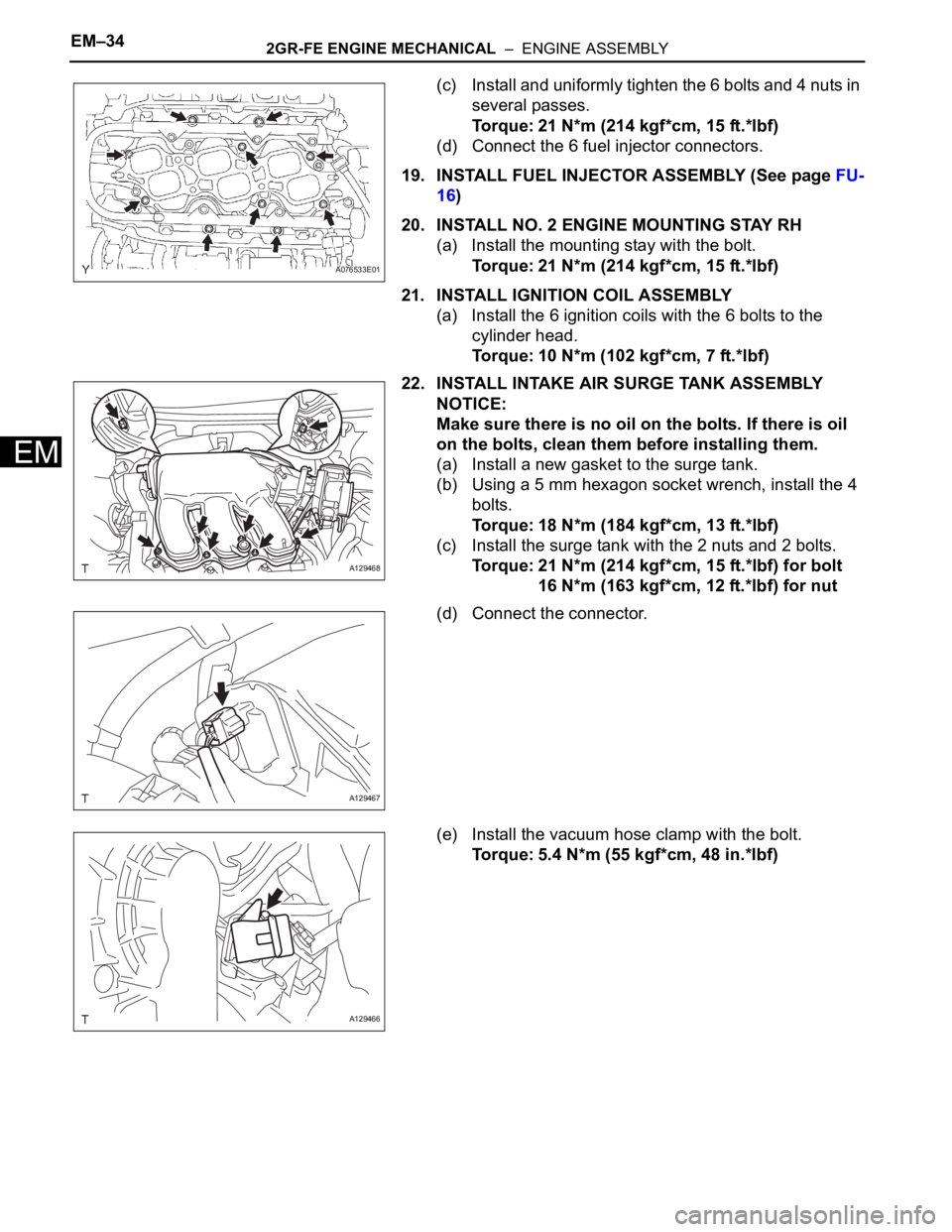
(c) Install and uniformly tighten the 6 bolts and 4 nuts in
several passes.
Torque: 21 N*m (214 kgf*cm, 15 ft.*lbf)
(d) Connect the 6 fuel injector connectors.
19. INSTALL FUEL INJECTOR ASSEMBLY (See page FU-
16)
20. INSTALL NO. 2 ENGINE MOUNTING STAY RH
(a) Install the mounting stay with the bolt.
Torque: 21 N*m (214 kgf*cm, 15 ft.*lbf)
21. INSTALL IGNITION COIL ASSEMBLY
(a) Install the 6 ignition coils with the 6 bolts to the
cylinder head.
Torque: 10 N*m (102 kgf*cm, 7 ft.*lbf)
22. INSTALL INTAKE AIR SURGE TANK ASSEMBLY
NOTICE:
Make sure there is no oil on the bolts. If there is oil
on the bolts, clean them before installing them.
(a) Install a new gasket to the surge tank.
(b) Using a 5 mm hexagon socket wrench, install the 4
bolts.
Torque: 18 N*m (184 kgf*cm, 13 ft.*lbf)
(c) Install the surge tank with the 2 nuts and 2 bolts.
Torque: 21 N*m (214 kgf*cm, 15 ft.*lbf) for bolt
16 N*m (163 kgf*cm, 12 ft.*lbf) for nut
(d) Connect the connector.
(e) Install the vacuum hose clamp with the bolt.
Torque: 5.4 N*m (55 kgf*cm, 48 in.*lbf)
A076533E01
A129468
A129467
A129466
Page 769 of 2000

2AZ-FE FUEL – FUEL INJECTORFU–9
FU
REMOVAL
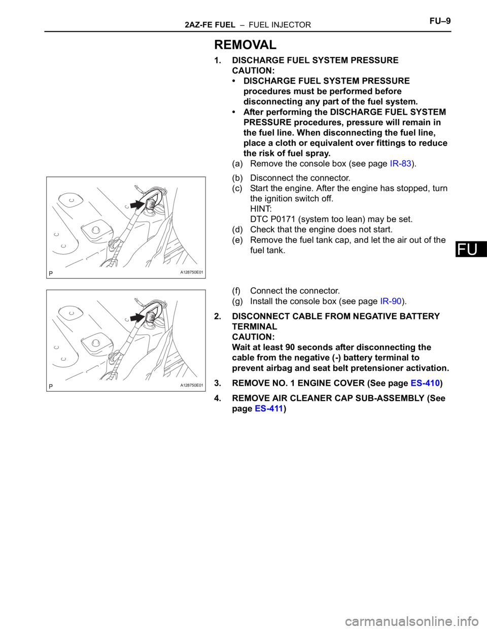
1. DISCHARGE FUEL SYSTEM PRESSURE
CAUTION:
• DISCHARGE FUEL SYSTEM PRESSURE
procedures must be performed before
disconnecting any part of the fuel system.
• After performing the DISCHARGE FUEL SYSTEM
PRESSURE procedures, pressure will remain in
the fuel line. When disconnecting the fuel line,
place a cloth or equivalent over fittings to reduce
the risk of fuel spray.
(a) Remove the console box (see page IR-83).
(b) Disconnect the connector.
(c) Start the engine. After the engine has stopped, turn
the ignition switch off.
HINT:
DTC P0171 (system too lean) may be set.
(d) Check that the engine does not start.
(e) Remove the fuel tank cap, and let the air out of the
fuel tank.
(f) Connect the connector.
(g) Install the console box (see page IR-90).
2. DISCONNECT CABLE FROM NEGATIVE BATTERY
TERMINAL
CAUTION:
Wait at least 90 seconds after disconnecting the
cable from the negative (-) battery terminal to
prevent airbag and seat belt pretensioner activation.
3. REMOVE NO. 1 ENGINE COVER (See page ES-410)
4. REMOVE AIR CLEANER CAP SUB-ASSEMBLY (See
page ES-411)
A128750E01
A128750E01
Page 770 of 2000

FU–102AZ-FE FUEL – FUEL INJECTOR
FU
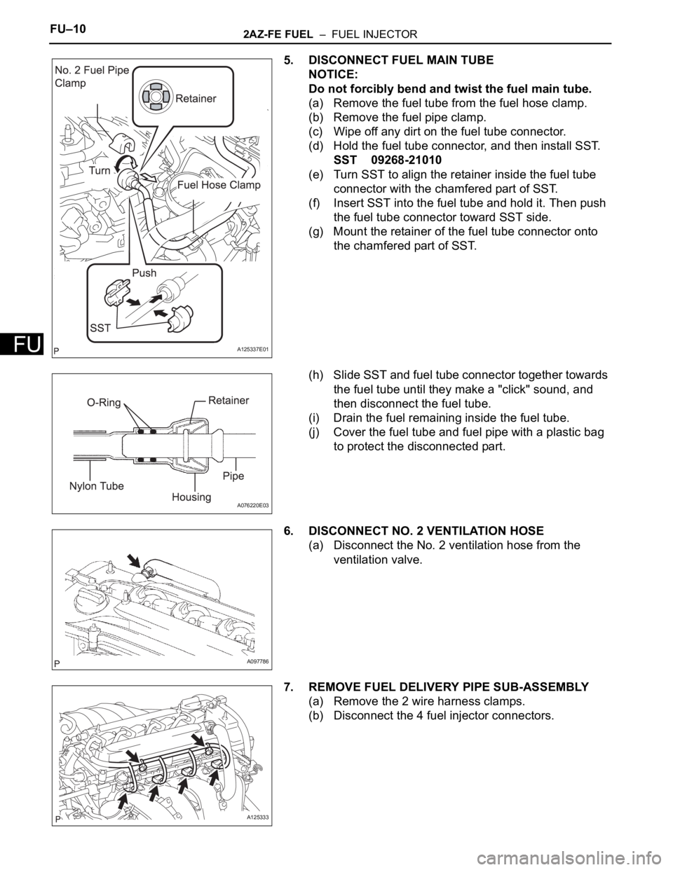
5. DISCONNECT FUEL MAIN TUBE
NOTICE:
Do not forcibly bend and twist the fuel main tube.
(a) Remove the fuel tube from the fuel hose clamp.
(b) Remove the fuel pipe clamp.
(c) Wipe off any dirt on the fuel tube connector.
(d) Hold the fuel tube connector, and then install SST.
SST 09268-21010
(e) Turn SST to align the retainer inside the fuel tube
connector with the chamfered part of SST.
(f) Insert SST into the fuel tube and hold it. Then push
the fuel tube connector toward SST side.
(g) Mount the retainer of the fuel tube connector onto
the chamfered part of SST.
(h) Slide SST and fuel tube connector together towards
the fuel tube until they make a "click" sound, and
then disconnect the fuel tube.
(i) Drain the fuel remaining inside the fuel tube.
(j) Cover the fuel tube and fuel pipe with a plastic bag
to protect the disconnected part.
6. DISCONNECT NO. 2 VENTILATION HOSE
(a) Disconnect the No. 2 ventilation hose from the
ventilation valve.
7. REMOVE FUEL DELIVERY PIPE SUB-ASSEMBLY
(a) Remove the 2 wire harness clamps.
(b) Disconnect the 4 fuel injector connectors.
A125337E01
A076220E03
A097786
A125333