Page 806 of 2000

FU–162GR-FE FUEL – FUEL INJECTOR
FU
INSPECTION
1. INSPECT FUEL INJECTOR ASSEMBLY
(a) Inspect injector resistance.
(1) Measure the resistance between the terminals.
Standard resistance:
11.6 to 12.4
at 20C (68F)
If the result is not as specified, replace the
injector.
(b) Inspect the injection volume.
CAUTION:
This test involves high-pressure fuel and
electricity. Take every precaution regarding safe
handling of both the fuel and the electricity.
Perform this test in a safe area, and avoid any
sparks or flames. Do not smoke.
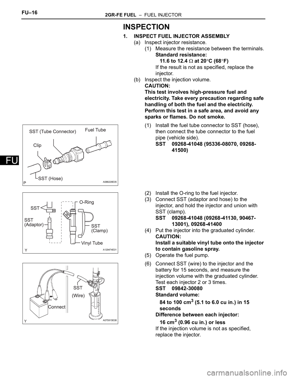
(1) Install the fuel tube connector to SST (hose),
then connect the tube connector to the fuel
pipe (vehicle side).
SST 09268-41048 (95336-08070, 09268-
41500)
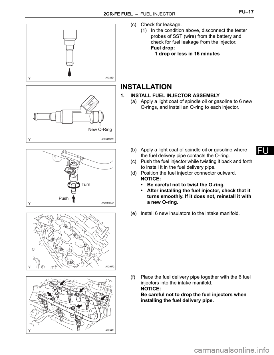
(2) Install the O-ring to the fuel injector.
(3) Connect SST (adaptor and hose) to the
injector, and hold the injector and union with
SST (clamp).
SST 09268-41048 (09268-41130, 90467-
13001), 09268-41400
(4) Put the injector into the graduated cylinder.
CAUTION:
Install a suitable vinyl tube onto the injector
to contain gasoline spray.
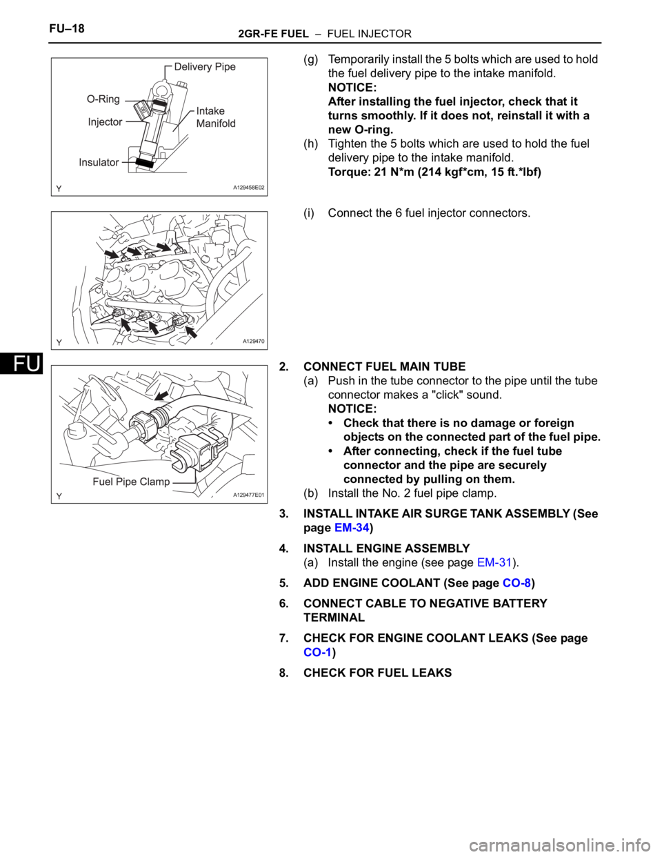
(5) Operate the fuel pump.
(6) Connect SST (wire) to the injector and the
battery for 15 seconds, and measure the
injection volume with the graduated cylinder.
Test each injector 2 or 3 times.
SST 09842-30080
Standard volume:
84 to 100 cm
3 (5.1 to 6.0 cu in.) in 15
seconds
Difference between each injector:
16 cm
3 (0.96 cu in.) or less
If the injection volume is not as specified,
replace the injector.
A088228E05
A129474E01
A075915E08
Page 807 of 2000

2GR-FE FUEL – FUEL INJECTORFU–17
FU
(c) Check for leakage.
(1) In the condition above, disconnect the tester
probes of SST (wire) from the battery and
check for fuel leakage from the injector.
Fuel drop:
1 drop or less in 16 minutes
INSTALLATION
1. INSTALL FUEL INJECTOR ASSEMBLY
(a) Apply a light coat of spindle oil or gasoline to 6 new
O-rings, and install an O-ring to each injector.
(b) Apply a light coat of spindle oil or gasoline where
the fuel delivery pipe contacts the O-ring.
(c) Push the fuel injector while twisting it back and forth
to install it in the fuel delivery pipe.
(d) Position the fuel injector connector outward.
NOTICE:
• Be careful not to twist the O-ring.
• After installing the fuel injector, check that it
turns smoothly. If it does not, reinstall it with
a new O-ring.
(e) Install 6 new insulators to the intake manifold.
(f) Place the fuel delivery pipe together with the 6 fuel
injectors into the intake manifold.
NOTICE:
Be careful not to drop the fuel injectors when
installing the fuel delivery pipe.
A132391
A129475E01
A129476E01
A129472
A129471
Page 808 of 2000

FU–182GR-FE FUEL – FUEL INJECTOR
FU
(g) Temporarily install the 5 bolts which are used to hold
the fuel delivery pipe to the intake manifold.
NOTICE:
After installing the fuel injector, check that it
turns smoothly. If it does not, reinstall it with a
new O-ring.
(h) Tighten the 5 bolts which are used to hold the fuel
delivery pipe to the intake manifold.
Torque: 21 N*m (214 kgf*cm, 15 ft.*lbf)
(i) Connect the 6 fuel injector connectors.
2. CONNECT FUEL MAIN TUBE
(a) Push in the tube connector to the pipe until the tube
connector makes a "click" sound.
NOTICE:
• Check that there is no damage or foreign
objects on the connected part of the fuel pipe.
• After connecting, check if the fuel tube
connector and the pipe are securely
connected by pulling on them.
(b) Install the No. 2 fuel pipe clamp.
3. INSTALL INTAKE AIR SURGE TANK ASSEMBLY (See
page EM-34)
4. INSTALL ENGINE ASSEMBLY
(a) Install the engine (see page EM-31).
5. ADD ENGINE COOLANT (See page CO-8)
6. CONNECT CABLE TO NEGATIVE BATTERY
TERMINAL
7. CHECK FOR ENGINE COOLANT LEAKS (See page
CO-1)
8. CHECK FOR FUEL LEAKS
A129458E02
A129470
A129477E01
Page 832 of 2000

EC–82GR-FE EMISSION CONTROL – EMISSION CONTROL SYSTEM
EC
ON-VEHICLE INSPECTION
1. CHECK FUEL CUT RPM
(a) Increase the engine speed to at least 3,500 rpm.
(b) Use a sound scope to check for injector operating
noise.
(c) Check that the operating sounds stop momentarily
and then resume when the throttle lever is released.
HINT:
Measure with the A/C OFF.
Fuel return rpm:
1,400 rpm
2. CHECK FOR LEAKS
(a) Visually check that the hoses, connections and
gaskets have no cracks, leaks or damage.
NOTICE:
• Detachment or other problems with the
engine oil dipstick, filler cap, PCV hose and
other components may cause the engine to
run improperly.
• Disconnection, looseness or cracks in the
parts of the air induction system between the
throttle body and cylinder head will allow air
suction and cause an engine failure or engine
malfunctions.
If the result is not as specified, replace parts as
necessary.
3. CHECK LINE AND CONNECTORS
(a) Visually check for loose connections, sharp bends
or damage.
4. CHECK FUEL TANK ASSEMBLY
(a) Visually check for deformation, cracks or fuel
leakage.
5. CHECK FUEL TANK AND VENT LINE
(a) Disconnect the vent line tube from the canister.
(b) Connect a pressure gauge to the vent line tube.
A094394E01
A127736E01
Page 885 of 2000

2AZ-FE IGNITION – IGNITION SYSTEMIG–5
IG
ON-VEHICLE INSPECTION
1. CHECK IGNITION COIL ASSEMBLY AND PERFORM
SPARK TEST
NOTICE:
In this section, the terms "cold" and "hot" refer to
the temperature of the coils. "Cold" means
approximately -10 to 50
C (14 to 122F). "Hot" means
approximately 50 to 100
C (122 to 212F).
(a) Check the DTCs.
NOTICE:
If a DTC is present, perform troubleshooting in
accordance with the procedure for that DTC.
(b) Check that sparks occur.
(1) Remove the No. 1 engine cover.
(2) Remove the bolt and ignition coil.
(3) Using a 16 mm spark plug wrench, remove the
spark plug.
(4) Disconnect the 4 fuel injector connectors.
(5) Install the spark plug into the ignition coil, and
then connect the ignition coil connectors.
(6) Ground the spark plug.
(7) Check that sparks occur at the spark plug while
the engine is being cranked.
NOTICE:
• Be sure to ground the spark plugs when
checking them.
• If the ignition coil has been struck or
dropped, replace it.
• Do not crank the engine for more than 2
seconds.
If sparks do not occur, Perform the spark test.
(8) Using a 16 mm plug wrench, install the spark
plug.
Torque: 25 N*m (254 kgf*cm, 18 ft.*lbf)
A124849E01
A097448E01
A124396
Page 886 of 2000

IG–62AZ-FE IGNITION – IGNITION SYSTEM
IG
(9) Install the ignition coil with the bolt.
Torque: 9.0 N*m (92 kgf*cm, 80 in.*lbf)
(10) Connect the 4 fuel injector connectors.
(11) Install the No. 1 engine cover.
(c) Spark test flow chart.
(1) Check that the ignition coil connector is
securely connected.
Result
(2) Perform the spark test on each ignition coil.
1. Replace the ignition coil with a normal one.
2. Perform the spark test again.
Result
(3) Check the power supply to the ignition coil.
1. Disconnect the ignition coil connector.
2. Turn the ignition switch ON.
3. Measure the voltage of the wire harness
side connector.
Standard voltage
Result
(4) Check the resistance of the camshaft position
sensor.
Standard resistance
Result
(5) Check the resistance of the crankshaft position
sensor.
Standard resistance
Result Proceed to
NG Connect securely
OK Go to next step
Result Proceed to
OK Replace ignition coil
NG Go to next step
A124397
Tester Connection Specified Condition
1 (+B) - 4 (GND) 9 to 14 V
Result Proceed to
NG Check wire harness and connector
OK Go to next step
Temperature Condition Specified Condition
Cold 835 to 1,400
Hot 1,060 to 1,645
Result Proceed to
NG Replace camshaft position sensor
OK Go to next step
Temperature Condition Specified Condition
Cold 985 to 1,600
Hot 1,265 to 1,890
Page 895 of 2000

2GR-FE IGNITION – IGNITION SYSTEMIG–5
IG
ON-VEHICLE INSPECTION
1. CHECK IGNITION COIL ASSEMBLY AND PERFORM
SPARK TEST
NOTICE:
In this section, the terms "Cold" and "Hot" refer to
the temperature of the sensor. "Cold" means
approximately -10 to 50
C (14 to 122F). "Hot" means
approximately 50 to 100
C (122 to 212F).
(a) Check the DTCs.
NOTICE:
If a DTC is present, perform troubleshooting in
accordance with the procedure for that DTC.
(b) Check that sparks occur.
(1) Remove the V-bank cover.
(2) Remove the intake air surge tank (see page
EM-27).
(3) Remove the bolt and ignition coil.
(4) Using a 16 mm spark plug wrench, remove the
spark plug.
(5) Disconnect the 6 fuel injector connectors.
(6) Install the spark plug into the ignition coil, and
then connect the ignition coil connectors.
(7) Ground the spark plug.
(8) Check that sparks occur at the spark plug while
the engine is being cranked.
NOTICE:
• Be sure to ground the spark plugs when
checking them.
• If the ignition coil has been struck or
dropped, replace it.
• Do not crank the engine for more than 2
seconds.
If sparks do not occur, perform troubleshooting
using the spark test flowchart.
(9) Using a 16 mm plug wrench, install the spark
plug.
Torque: 25 N*m (254 kgf*cm, 18 ft.*lbf)
(10) Install the ignition coil with the bolt.
Torque: 10 N*m (102 kgf*cm, 7 ft.*lbf)
(11) Connect the 6 fuel injector connectors.
(12) Install the intake air surge tank (see page EM-
34).
(13) Install the V-bank cover.
A136823
A136826
Page 1620 of 2000
PS–20POWER STEERING – ELECTRONIC POWER STEERING SYSTEM
PS
HINT:
: Warning light comes on
X: Warning light turns off (normal reset)
U0105/41 Lost Communication
with Fuel Injector
Control Module- CAN
communication
system
- ECMIgnition switch ON
again or after normal
confirmationX PS-34
U0121/42 Lost Communication
with Anti-Lock Brake
System (ABS)
Control Module- CAN
communication
system
- Skid control ECUIgnition switch ON
again or after normal
confirmation
PS-34 DTC No. Detection Item Trouble Area Normal Function
Return ConditionP/S Warning Light See page