2006 NISSAN PATROL battery
[x] Cancel search: batteryPage 607 of 1226
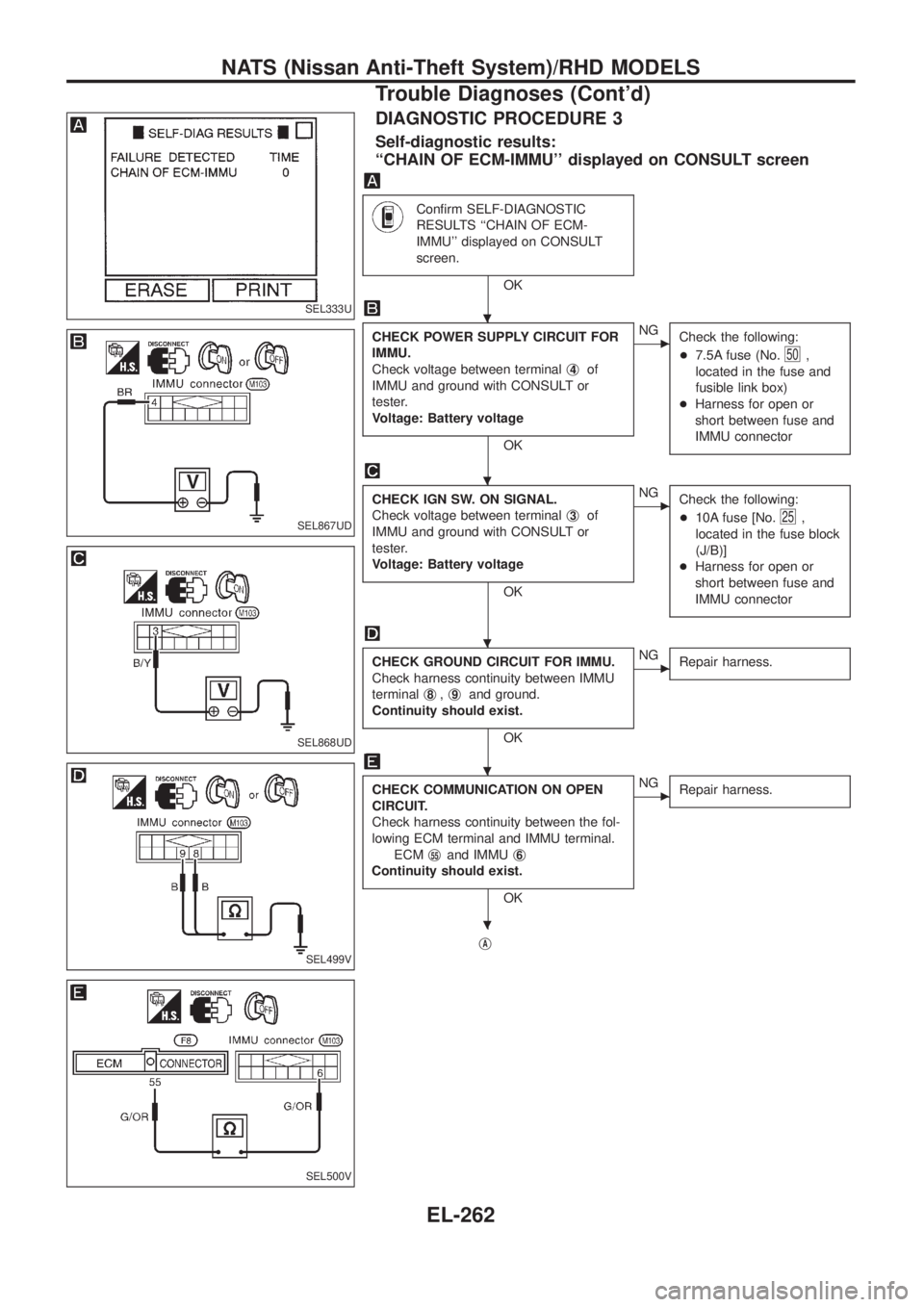
DIAGNOSTIC PROCEDURE 3
Self-diagnostic results:
``CHAIN OF ECM-IMMU'' displayed on CONSULT screen
Con®rm SELF-DIAGNOSTIC
RESULTS ``CHAIN OF ECM-
IMMU'' displayed on CONSULT
screen.
OK
CHECK POWER SUPPLY CIRCUIT FOR
IMMU.
Check voltage between terminalj
4of
IMMU and ground with CONSULT or
tester.
Voltage: Battery voltage
OK
cNG
Check the following:
+7.5A fuse (No.
50,
located in the fuse and
fusible link box)
+Harness for open or
short between fuse and
IMMU connector
CHECK IGN SW. ON SIGNAL.
Check voltage between terminalj
3of
IMMU and ground with CONSULT or
tester.
Voltage: Battery voltage
OK
cNG
Check the following:
+10A fuse [No.
25,
located in the fuse block
(J/B)]
+Harness for open or
short between fuse and
IMMU connector
CHECK GROUND CIRCUIT FOR IMMU.
Check harness continuity between IMMU
terminalj
8,j9and ground.
Continuity should exist.
OK
cNG
Repair harness.
CHECK COMMUNICATION ON OPEN
CIRCUIT.
Check harness continuity between the fol-
lowing ECM terminal and IMMU terminal.
ECMj
55and IMMUj6
Continuity should exist.
OK
cNG
Repair harness.
jA
SEL333U
SEL867UD
SEL868UD
SEL499V
SEL500V
.
.
.
.
.
NATS (Nissan Anti-Theft System)/RHD MODELS
Trouble Diagnoses (Cont'd)
EL-262
Page 612 of 1226
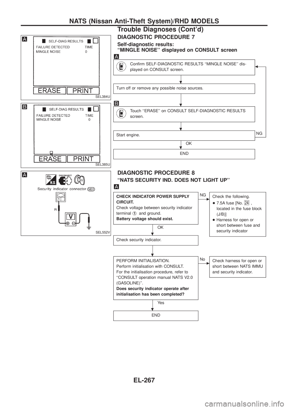
DIAGNOSTIC PROCEDURE 7
Self-diagnostic results:
``MINGLE NOISE'' displayed on CONSULT screen
Con®rm SELF-DIAGNOSTIC RESULTS ``MINGLE NOISE'' dis-
played on CONSULT screen.b
Turn off or remove any possible noise sources.
Touch ``ERASE'' on CONSULT SELF-DIAGNOSTIC RESULTS
screen.
Start engine.
OKNG
END
DIAGNOSTIC PROCEDURE 8
``NATS SECURITY IND. DOES NOT LIGHT UP''
CHECK INDICATOR POWER SUPPLY
CIRCUIT.
Check voltage between security indicator
terminalj
1and ground.
Battery voltage should exist.
OK
cNG
Check the following.
+7.5A fuse [No.
24,
located in the fuse block
(J/B)]
+Harness for open or
short between fuse and
security indicator
Check security indicator.
PERFORM INITIALISATION.
Perform initialisation with CONSULT.
For the initialisation procedure, refer to
``CONSULT operation manual NATS V2.0
(GASOLINE)''.
Does security indicator operate after
initialisation has been completed?
Ye s
cNo
Check harness for open or
short between NATS IMMU
and security indicator.
END
SEL384U
SEL385U
SEL552V
.
.
.
.
.
.
.
NATS (Nissan Anti-Theft System)/RHD MODELS
Trouble Diagnoses (Cont'd)
EL-267
Page 773 of 1226
GENERAL INFORMATION
SECTION
GI
CONTENTS
PRECAUTIONS...............................................................1
Precaution for Supplemental Restraint System
(SRS) ``AIR BAG'' and ``SEAT BELT
PRE-TENSIONER'' ......................................................1
General Precautions ....................................................2
Precautions for Multiport Fuel Injection System
or ECCS Engine ..........................................................3
Precautions for Three Way Catalyst
(If so equipped)............................................................4
Precautions for Engine Oils .........................................4
Precautions for Fuel ....................................................5
Precautions for Air Conditioning ..................................5
HOW TO USE THIS MANUAL........................................6
HOW TO READ WIRING DIAGRAMS............................8
Sample/Wiring Diagram Ð EXAMPL Ð......................8
Description .................................................................10
HOW TO CHECK TERMINAL.......................................17
How to Probe Connectors .........................................17
How to Check Enlarged Contact Spring of
Terminal .....................................................................18
Waterproof Connector Inspection ..............................19
Terminal Lock Inspection ...........................................19
HOW TO PERFORM EFFICIENT DIAGNOSIS FOR
AN ELECTRICAL INCIDENT........................................20Work Flow ..................................................................20
Incident Simulation Tests ...........................................21
Circuit Inspection .......................................................24
HOW TO FOLLOW FLOW CHART IN TROUBLE
DIAGNOSES..................................................................30
How to Follow This Flow Chart .................................31
CONSULT CHECKING SYSTEM..................................33
Function and System Application ..............................33
Lithium Battery Replacement ....................................33
Checking Equipment..................................................33
Loading Procedure ....................................................34
CONSULT Data Link Connector (DLC) Circuit..........34
IDENTIFICATION INFORMATION.................................35
Model Variation ..........................................................35
Identi®cation Number .................................................36
Dimensions ................................................................38
Wheels & Tires ..........................................................38
LIFTING POINTS AND TOW TRUCK TOWING...........39
Screw Jack ................................................................39
Garage Jack and Safety Stand .................................39
2-pole Lift ...................................................................40
Tow Truck Towing ......................................................41
SAE J1930 TERMINOLOGY LIST................................43
SAE J1930 Terminology List .....................................43
GI
Page 775 of 1226

General Precautions
+Do not operate the engine for an extended period of time with-
out proper exhaust ventilation.
Keep the work area well ventilated and free of any in¯ammable
materials. Special care should be taken when handling any
in¯ammable or poisonous materials, such as gasoline, refriger-
ant gas, etc. When working in a pit or other enclosed area, be
sure to properly ventilate the area before working with hazard-
ous materials.
Do not smoke while working on the vehicle.
+Before jacking up the vehicle, apply wheel chocks or other tire
blocks to the wheels to prevent the vehicle from moving. After
jacking up the vehicle, support the vehicle weight with safety
stands at the points designated for proper lifting before work-
ing on the vehicle.
These operations should be done on a level surface.
+When removing a heavy component such as the engine or
transaxle/transmission, be careful not to lose your balance and
drop it. Also, do not allow it to strike adjacent parts, especially
the brake tubes and master cylinder.
+Before starting repairs which do not require battery power:
Turn off ignition switch.
Disconnect the negative battery terminal.
+To prevent serious burns:
Avoid contact with hot metal parts.
Do not remove the radiator cap when the engine is hot.
+Before servicing the vehicle:
Protect fenders, upholstery and carpeting with appropriate cov-
ers.
Take caution that keys, buckles or buttons do not scratch paint.
SGI285
SGI231
SEF289H
SGI233
SGI234
PRECAUTIONS
GI-2
Page 776 of 1226
+Clean all disassembled parts in the designated liquid or solvent
prior to inspection or assembly.
+Replace oil seals, gaskets, packings, O-rings, locking washers,
cotter pins, self-locking nuts, etc. with new ones.
+Replace inner and outer races of tapered roller bearings and
needle bearings as a set.
+Arrange the disassembled parts in accordance with their
assembled locations and sequence.
+Do not touch the terminals of electrical components which use
microcomputers (such as ECMs).
Static electricity may damage internal electronic components.
+After disconnecting vacuum or air hoses, attach a tag to indi-
cate the proper connection.
+Use only the ¯uids and lubricants speci®ed in this manual.
+Use approved bonding agent, sealants or their equivalents
when required.
+Use tools and recommended special tools where speci®ed for
safe and efficient service repairs.
+When repairing the fuel, oil, water, vacuum or exhaust systems,
check all affected lines for leaks.
+Dispose of drained oil or the solvent used for cleaning parts in
an appropriate manner.
WARNING:
To prevent ECM from storing the diagnostic trouble codes, do
not carelessly disconnect the harness connectors which are
related to the ECCS system and TCM (Transmission Control
Module) system. The connectors should be disconnected only
when working according to the WORK FLOW of TROUBLE
DIAGNOSES in EC and AT sections.
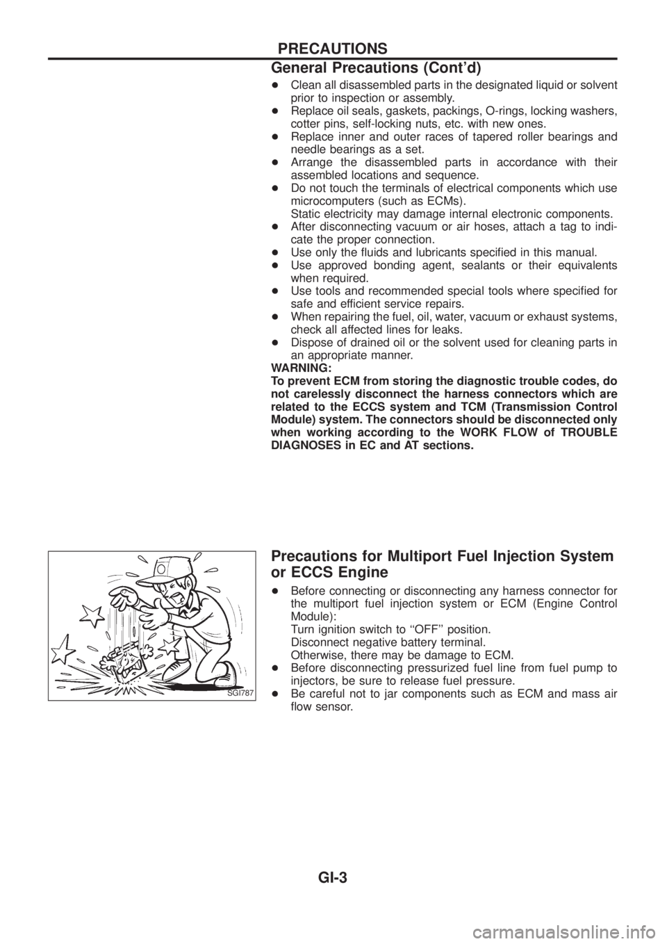
Precautions for Multiport Fuel Injection System
or ECCS Engine
+Before connecting or disconnecting any harness connector for
the multiport fuel injection system or ECM (Engine Control
Module):
Turn ignition switch to ``OFF'' position.
Disconnect negative battery terminal.
Otherwise, there may be damage to ECM.
+
Before disconnecting pressurized fuel line from fuel pump to
injectors, be sure to release fuel pressure.
+Be careful not to jar components such as ECM and mass air
¯ow sensor.SGI787
PRECAUTIONS
General Precautions (Cont'd)
GI-3
Page 783 of 1226
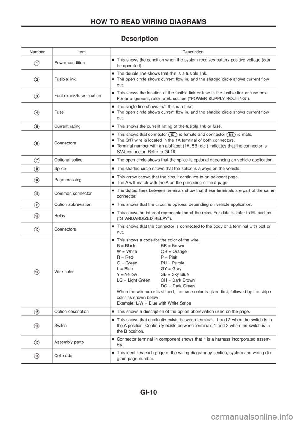
Description
Number Item Description
V1Power condition+This shows the condition when the system receives battery positive voltage (can
be operated).
V2Fusible link+The double line shows that this is a fusible link.
+The open circle shows current ¯ow in, and the shaded circle shows current ¯ow
out.
V3Fusible link/fuse location+This shows the location of the fusible link or fuse in the fusible link or fuse box.
For arrangement, refer to EL section (``POWER SUPPLY ROUTING'').
V4Fuse+The single line shows that this is a fuse.
+The open circle shows current ¯ow in, and the shaded circle shows current ¯ow
out.
V5Current rating+This shows the current rating of the fusible link or fuse.
V6Connectors+This shows that connector
E3is female and connectorM1is male.
+The G/R wire is located in the 1A terminal of both connectors.
+Terminal number with an alphabet (1A, 5B, etc.) indicates that the connector is
SMJ connector. Refer to GI-16.
V7Optional splice+The open circle shows that the splice is optional depending on vehicle application.
V8Splice+The shaded circle shows that the splice is always on the vehicle.
V9Page crossing+This arrow shows that the circuit continues to an adjacent page.
+The A will match with the A on the preceding or next page.
V10Common connector+The dotted lines between terminals show that these terminals are part of the same
connector.
V11Option abbreviation+This shows that the circuit is optional depending on vehicle application.
V12Relay+This shows an internal representation of the relay. For details, refer to EL section
(``STANDARDIZED RELAY'').
V13Connectors+This shows that the connector is connected to the body or a terminal with bolt or
nut.
V14Wire color+This shows a code for the color of the wire.
B = Black BR = Brown
W = White OR = Orange
R = Red P = Pink
G = Green PU = Purple
L = Blue GY = Gray
Y = Yellow SB = Sky Blue
LG = Light Green CH = Dark Brown
DG = Dark Green
When the wire color is striped, the base color is given ®rst, followed by the stripe
color as shown below:
Example: L/W = Blue with White Stripe
V15Option description+This shows a description of the option abbreviation used on the page.
V16Switch+This shows that continuity exists between terminals 1 and 2 when the switch is in
the A position. Continuity exists between terminals 1 and 3 when the switch is in
the B position.
V17Assembly parts+Connector terminal in component shows that it is a harness incorporated assem-
bly.
V18Cell code+This identi®es each page of the wiring diagram by section, system and wiring dia-
gram page number.
HOW TO READ WIRING DIAGRAMS
GI-10
Page 797 of 1226
Circuit Inspection
INTRODUCTION
In general, testing electrical circuits is an easy task if it is approached in a logical and organized method. Before
beginning it is important to have all available information on the system to be tested. Also, get a thorough
understanding of system operation. Then you will be able to use the appropriate equipment and follow the
correct test procedure.
You may have to simulate vehicle vibrations while testing electrical components.Gently shakethe wiring
harness or electrical component to do this.
OPEN A circuit is open when there is no continuity through a section of the circuit.
SHORT There are two types of shorts.
+SHORT CIRCUITWhen a circuit contacts another circuit and causes the
normal resistance to change.
+SHORT TO GROUNDWhen a circuit contacts a ground source and grounds the
circuit.
TESTING FOR ``OPENS'' IN THE CIRCUIT
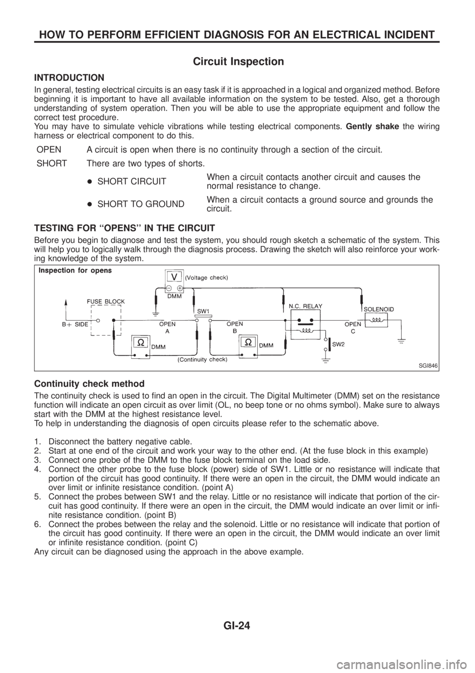
Before you begin to diagnose and test the system, you should rough sketch a schematic of the system. This
will help you to logically walk through the diagnosis process. Drawing the sketch will also reinforce your work-
ing knowledge of the system.
Continuity check method
The continuity check is used to ®nd an open in the circuit. The Digital Multimeter (DMM) set on the resistance
function will indicate an open circuit as over limit (OL, no beep tone or no ohms symbol). Make sure to always
start with the DMM at the highest resistance level.
To help in understanding the diagnosis of open circuits please refer to the schematic above.
1. Disconnect the battery negative cable.
2. Start at one end of the circuit and work your way to the other end. (At the fuse block in this example)
3. Connect one probe of the DMM to the fuse block terminal on the load side.
4. Connect the other probe to the fuse block (power) side of SW1. Little or no resistance will indicate that
portion of the circuit has good continuity. If there were an open in the circuit, the DMM would indicate an
over limit or in®nite resistance condition. (point A)
5. Connect the probes between SW1 and the relay. Little or no resistance will indicate that portion of the cir-
cuit has good continuity. If there were an open in the circuit, the DMM would indicate an over limit or in®-
nite resistance condition. (point B)
6. Connect the probes between the relay and the solenoid. Little or no resistance will indicate that portion of
the circuit has good continuity. If there were an open in the circuit, the DMM would indicate an over limit
or in®nite resistance condition. (point C)
Any circuit can be diagnosed using the approach in the above example.
SGI846
HOW TO PERFORM EFFICIENT DIAGNOSIS FOR AN ELECTRICAL INCIDENT
GI-24
Page 798 of 1226
Voltage check method
To help in understanding the diagnosis of open circuits please refer to the previous schematic.
In any powered circuit, an open can be found by methodically checking the system for the presence of volt-
age. This is done by switching the DMM to the voltage function.
1. Connect one probe of the DMM to a known good ground.
2. Begin probing at one end of the circuit and work your way to the other end.
3. With SW1 open, probe at SW1 to check for voltage.
voltage; open is further down the circuit than SW1.
no voltage; open is between fuse block and SW1 (point A).
4. Close SW1 and probe at relay.
voltage; open is further down the circuit than the relay.
no voltage; open is between SW1 and relay (point B).
5. Close the relay and probe at the solenoid.
voltage; open is further down the circuit than the solenoid.
no voltage; open is between relay and solenoid (point C).
Any powered circuit can be diagnosed using the approach in the above example.
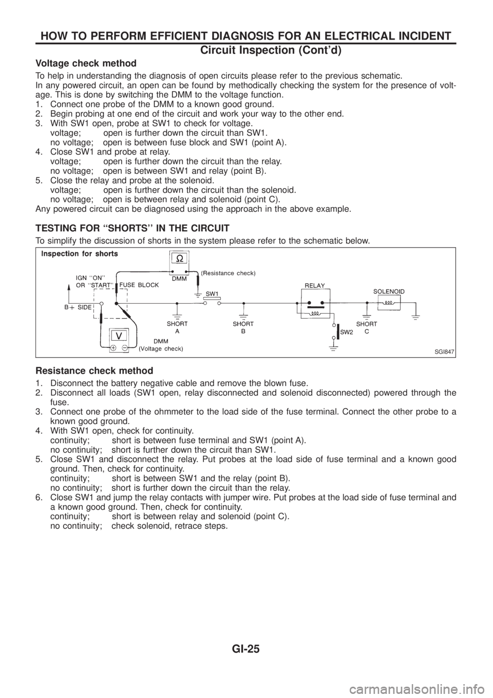
TESTING FOR ``SHORTS'' IN THE CIRCUIT
To simplify the discussion of shorts in the system please refer to the schematic below.
Resistance check method
1. Disconnect the battery negative cable and remove the blown fuse.
2. Disconnect all loads (SW1 open, relay disconnected and solenoid disconnected) powered through the
fuse.
3. Connect one probe of the ohmmeter to the load side of the fuse terminal. Connect the other probe to a
known good ground.
4. With SW1 open, check for continuity.
continuity; short is between fuse terminal and SW1 (point A).
no continuity; short is further down the circuit than SW1.
5. Close SW1 and disconnect the relay. Put probes at the load side of fuse terminal and a known good
ground. Then, check for continuity.
continuity; short is between SW1 and the relay (point B).
no continuity; short is further down the circuit than the relay.
6. Close SW1 and jump the relay contacts with jumper wire. Put probes at the load side of fuse terminal and
a known good ground. Then, check for continuity.
continuity; short is between relay and solenoid (point C).
no continuity; check solenoid, retrace steps.
SGI847
HOW TO PERFORM EFFICIENT DIAGNOSIS FOR AN ELECTRICAL INCIDENT
Circuit Inspection (Cont'd)
GI-25