2006 NISSAN PATROL battery
[x] Cancel search: batteryPage 959 of 1226
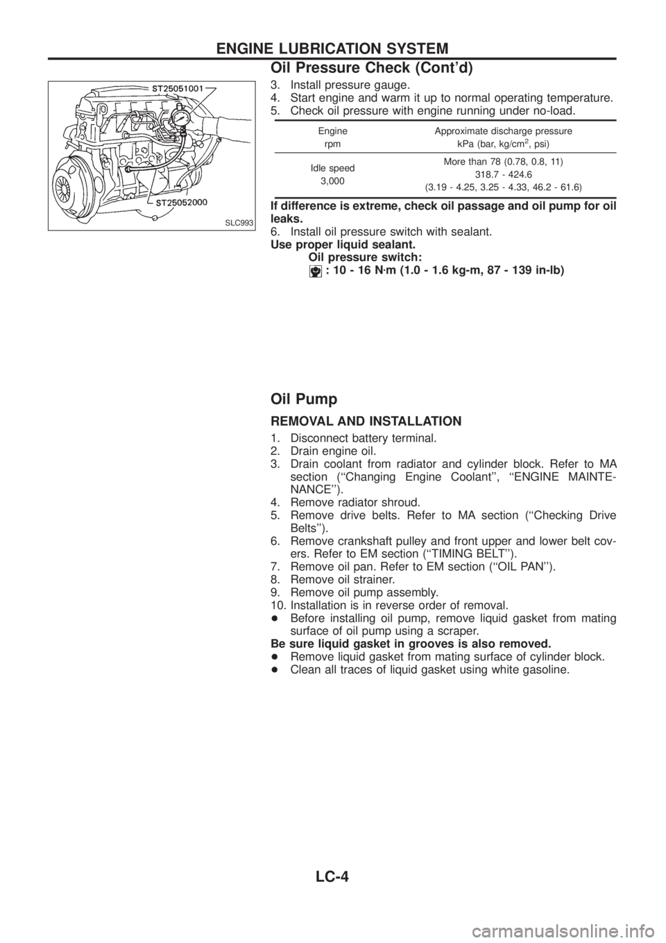
3. Install pressure gauge.
4. Start engine and warm it up to normal operating temperature.
5. Check oil pressure with engine running under no-load.
Engine
rpmApproximate discharge pressure
kPa (bar, kg/cm2, psi)
Idle speed
3,000More than 78 (0.78, 0.8, 11)
318.7 - 424.6
(3.19 - 4.25, 3.25 - 4.33, 46.2 - 61.6)
If difference is extreme, check oil passage and oil pump for oil
leaks.
6. Install oil pressure switch with sealant.
Use proper liquid sealant.
Oil pressure switch:
:10-16Nzm (1.0 - 1.6 kg-m, 87 - 139 in-lb)
Oil Pump
REMOVAL AND INSTALLATION
1. Disconnect battery terminal.
2. Drain engine oil.
3. Drain coolant from radiator and cylinder block. Refer to MA
section (``Changing Engine Coolant'', ``ENGINE MAINTE-
NANCE'').
4. Remove radiator shroud.
5. Remove drive belts. Refer to MA section (``Checking Drive
Belts'').
6. Remove crankshaft pulley and front upper and lower belt cov-
ers. Refer to EM section (``TIMING BELT'').
7. Remove oil pan. Refer to EM section (``OIL PAN'').
8. Remove oil strainer.
9. Remove oil pump assembly.
10. Installation is in reverse order of removal.
+Before installing oil pump, remove liquid gasket from mating
surface of oil pump using a scraper.
Be sure liquid gasket in grooves is also removed.
+Remove liquid gasket from mating surface of cylinder block.
+Clean all traces of liquid gasket using white gasoline.
SLC993
ENGINE LUBRICATION SYSTEM
Oil Pressure Check (Cont'd)
LC-4
Page 979 of 1226
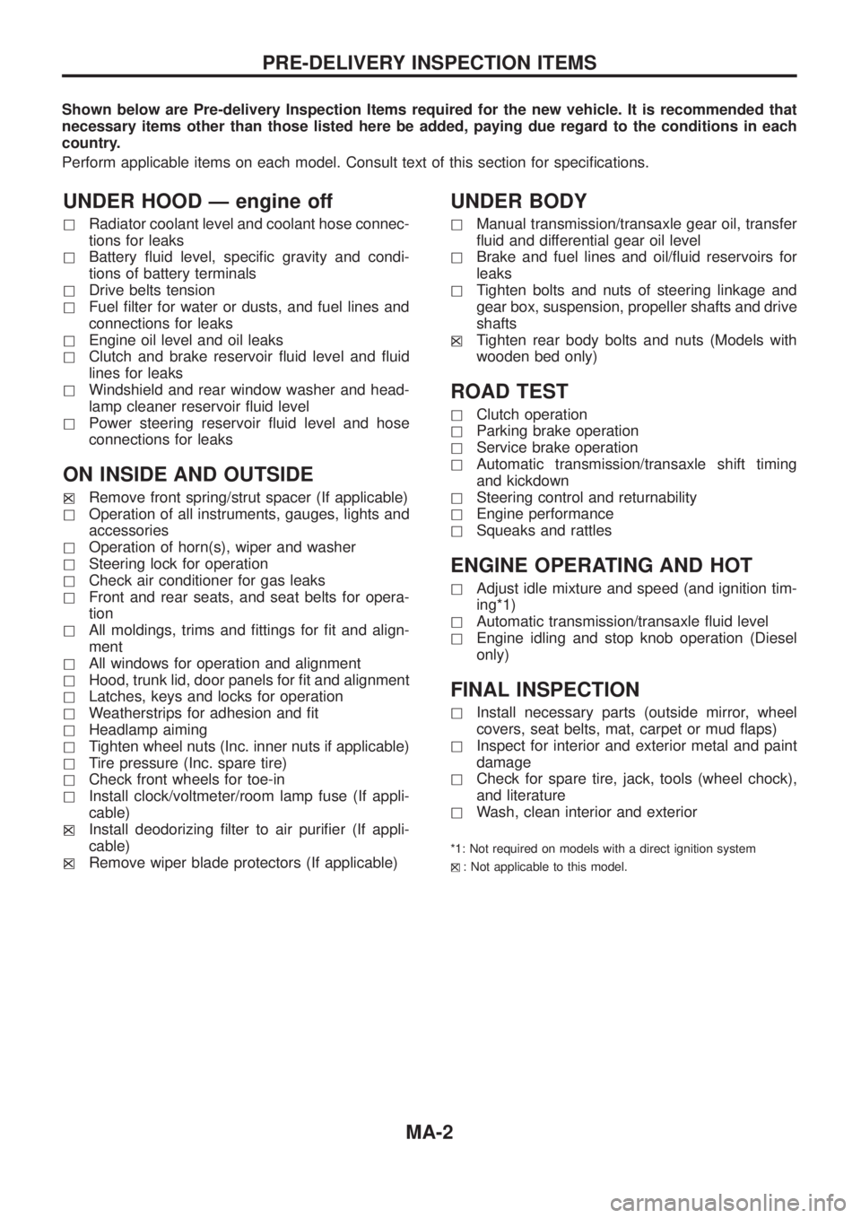
Shown below are Pre-delivery Inspection Items required for the new vehicle. It is recommended that
necessary items other than those listed here be added, paying due regard to the conditions in each
country.
Perform applicable items on each model. Consult text of this section for speci®cations.
UNDER HOOD Ð engine off
hRadiator coolant level and coolant hose connec-
tions for leaks
hBattery ¯uid level, speci®c gravity and condi-
tions of battery terminals
hDrive belts tension
hFuel ®lter for water or dusts, and fuel lines and
connections for leaks
hEngine oil level and oil leaks
hClutch and brake reservoir ¯uid level and ¯uid
lines for leaks
hWindshield and rear window washer and head-
lamp cleaner reservoir ¯uid level
hPower steering reservoir ¯uid level and hose
connections for leaks
ON INSIDE AND OUTSIDE
hXRemove front spring/strut spacer (If applicable)
hOperation of all instruments, gauges, lights and
accessories
hOperation of horn(s), wiper and washer
hSteering lock for operation
hCheck air conditioner for gas leaks
hFront and rear seats, and seat belts for opera-
tion
hAll moldings, trims and ®ttings for ®t and align-
ment
hAll windows for operation and alignment
hHood, trunk lid, door panels for ®t and alignment
hLatches, keys and locks for operation
hWeatherstrips for adhesion and ®t
hHeadlamp aiming
hTighten wheel nuts (Inc. inner nuts if applicable)
hTire pressure (Inc. spare tire)
hCheck front wheels for toe-in
hInstall clock/voltmeter/room lamp fuse (If appli-
cable)
h
XInstall deodorizing ®lter to air puri®er (If appli-
cable)
h
XRemove wiper blade protectors (If applicable)
UNDER BODY
hManual transmission/transaxle gear oil, transfer
¯uid and differential gear oil level
hBrake and fuel lines and oil/¯uid reservoirs for
leaks
hTighten bolts and nuts of steering linkage and
gear box, suspension, propeller shafts and drive
shafts
h
XTighten rear body bolts and nuts (Models with
wooden bed only)
ROAD TEST
hClutch operation
hParking brake operation
hService brake operation
hAutomatic transmission/transaxle shift timing
and kickdown
hSteering control and returnability
hEngine performance
hSqueaks and rattles
ENGINE OPERATING AND HOT
hAdjust idle mixture and speed (and ignition tim-
ing*1)
hAutomatic transmission/transaxle ¯uid level
hEngine idling and stop knob operation (Diesel
only)
FINAL INSPECTION
hInstall necessary parts (outside mirror, wheel
covers, seat belts, mat, carpet or mud ¯aps)
hInspect for interior and exterior metal and paint
damage
hCheck for spare tire, jack, tools (wheel chock),
and literature
hWash, clean interior and exterior
*1: Not required on models with a direct ignition system
h
X: Not applicable to this model.
PRE-DELIVERY INSPECTION ITEMS
MA-2
Page 980 of 1226
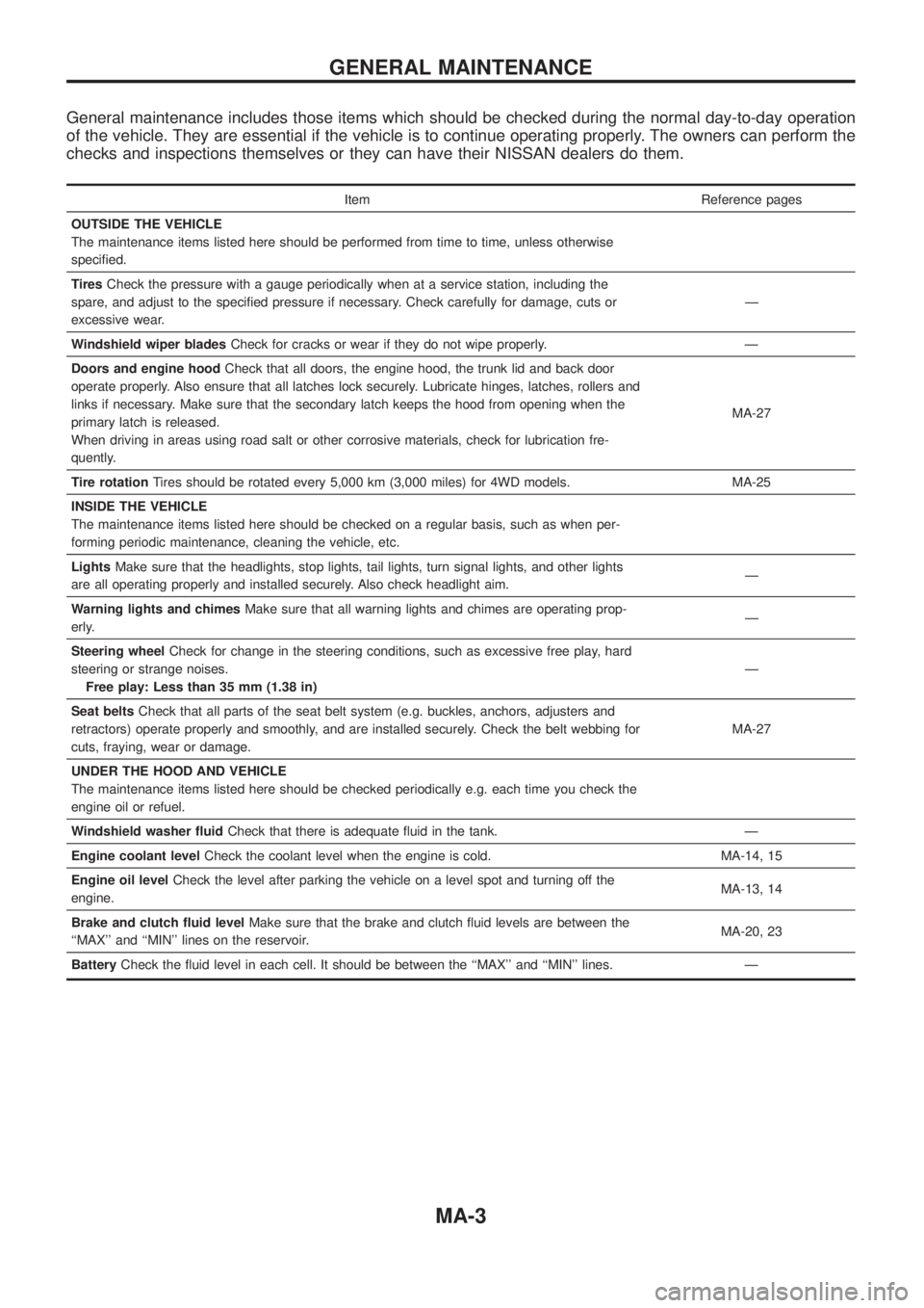
General maintenance includes those items which should be checked during the normal day-to-day operation
of the vehicle. They are essential if the vehicle is to continue operating properly. The owners can perform the
checks and inspections themselves or they can have their NISSAN dealers do them.
Item Reference pages
OUTSIDE THE VEHICLE
The maintenance items listed here should be performed from time to time, unless otherwise
speci®ed.
TiresCheck the pressure with a gauge periodically when at a service station, including the
spare, and adjust to the speci®ed pressure if necessary. Check carefully for damage, cuts or
excessive wear.Ð
Windshield wiper bladesCheck for cracks or wear if they do not wipe properly. Ð
Doors and engine hoodCheck that all doors, the engine hood, the trunk lid and back door
operate properly. Also ensure that all latches lock securely. Lubricate hinges, latches, rollers and
links if necessary. Make sure that the secondary latch keeps the hood from opening when the
primary latch is released.
When driving in areas using road salt or other corrosive materials, check for lubrication fre-
quently.MA-27
Tire rotationTires should be rotated every 5,000 km (3,000 miles) for 4WD models. MA-25
INSIDE THE VEHICLE
The maintenance items listed here should be checked on a regular basis, such as when per-
forming periodic maintenance, cleaning the vehicle, etc.
LightsMake sure that the headlights, stop lights, tail lights, turn signal lights, and other lights
are all operating properly and installed securely. Also check headlight aim.Ð
Warning lights and chimesMake sure that all warning lights and chimes are operating prop-
erly.Ð
Steering wheelCheck for change in the steering conditions, such as excessive free play, hard
steering or strange noises.
Free play: Less than 35 mm (1.38 in)Ð
Seat beltsCheck that all parts of the seat belt system (e.g. buckles, anchors, adjusters and
retractors) operate properly and smoothly, and are installed securely. Check the belt webbing for
cuts, fraying, wear or damage.MA-27
UNDER THE HOOD AND VEHICLE
The maintenance items listed here should be checked periodically e.g. each time you check the
engine oil or refuel.
Windshield washer ¯uidCheck that there is adequate ¯uid in the tank. Ð
Engine coolant levelCheck the coolant level when the engine is cold. MA-14, 15
Engine oil levelCheck the level after parking the vehicle on a level spot and turning off the
engine.MA-13, 14
Brake and clutch ¯uid levelMake sure that the brake and clutch ¯uid levels are between the
``MAX'' and ``MIN'' lines on the reservoir.MA-20, 23
BatteryCheck the ¯uid level in each cell. It should be between the ``MAX'' and ``MIN'' lines. Ð
GENERAL MAINTENANCE
MA-3
Page 1116 of 1226
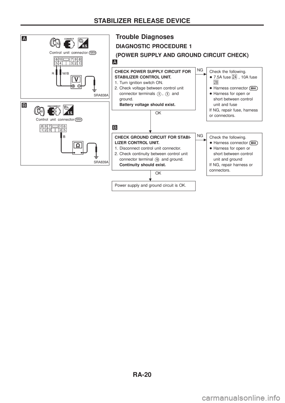
Trouble Diagnoses
DIAGNOSTIC PROCEDURE 1
(POWER SUPPLY AND GROUND CIRCUIT CHECK)
CHECK POWER SUPPLY CIRCUIT FOR
STABILIZER CONTROL UNIT.
1. Turn ignition switch ON.
2. Check voltage between control unit
connector terminals
V4,V5and
ground.
Battery voltage should exist.
OK
cNG
Check the following.
+7.5A fuse
24, 10A fuse
28
+Harness connectorM44
+Harness for open or
short between control
unit and fuse
If NG, repair fuse, harness
or connectors.
CHECK GROUND CIRCUIT FOR STABI-
LIZER CONTROL UNIT.
1. Disconnect control unit connector.
2. Check continuity between control unit
connector terminal
V10and ground.
Continuity should exist.
OK
cNG
Check the following.
+Harness connector
M44
+Harness for open or
short between control
unit and ground
If NG, repair harness or
connectors.
Power supply and ground circuit is OK.
SRA838A
SRA839A
.
.
STABILIZER RELEASE DEVICE
RA-20
Page 1118 of 1226
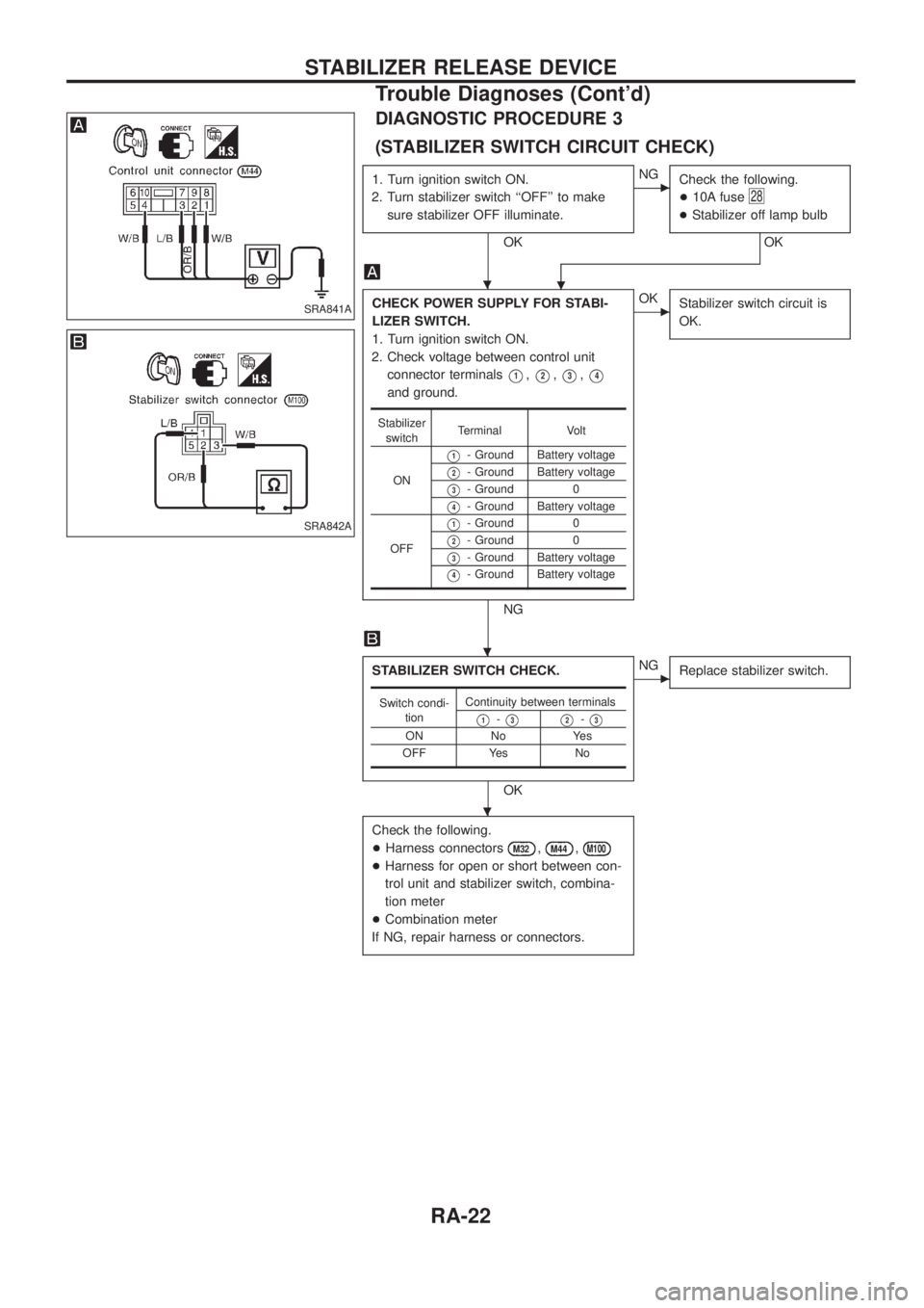
DIAGNOSTIC PROCEDURE 3
(STABILIZER SWITCH CIRCUIT CHECK)
1. Turn ignition switch ON.
2. Turn stabilizer switch ``OFF'' to make
sure stabilizer OFF illuminate.
OK
cNG
Check the following.
+10A fuse
28
+Stabilizer off lamp bulb
OK
.
CHECK POWER SUPPLY FOR STABI-
LIZER SWITCH.
1. Turn ignition switch ON.
2. Check voltage between control unit
connector terminals
V1,V2,V3,V4
and ground.
NG
cOK
Stabilizer switch circuit is
OK.
STABILIZER SWITCH CHECK.
OK
cNG
Replace stabilizer switch.
Check the following.
+Harness connectors
M32,M44,M100
+Harness for open or short between con-
trol unit and stabilizer switch, combina-
tion meter
+Combination meter
If NG, repair harness or connectors.
Stabilizer
switchTerminal Volt
ON
V1- Ground Battery voltage
V2- Ground Battery voltage
V3- Ground 0
V4- Ground Battery voltage
OFF
V1- Ground 0
V2- Ground 0
V3- Ground Battery voltage
V4- Ground Battery voltage
Switch condi-
tionContinuity between terminals
V1-V3V2-V3
ON No Yes
OFF Yes No
SRA841A
SRA842A
.
.
.
STABILIZER RELEASE DEVICE
Trouble Diagnoses (Cont'd)
RA-22
Page 1119 of 1226
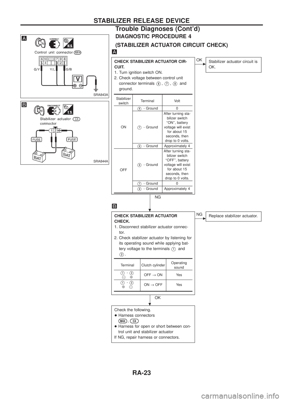
DIAGNOSTIC PROCEDURE 4
(STABILIZER ACTUATOR CIRCUIT CHECK)
CHECK STABILIZER ACTUATOR CIR-
CUIT.
1. Turn ignition switch ON.
2. Check voltage between control unit
connector terminals
V6,V7,V8and
ground.
NG
cOK
Stabilizer actuator circuit is
OK.
CHECK STABILIZER ACTUATOR
CHECK.
1. Disconnect stabilizer actuator connec-
tor.
2. Check stabilizer actuator by listening for
its operating sound while applying bat-
tery voltage to the terminals
V1and
V2.
OK
cNG
Replace stabilizer actuator.
Check the following.
+Harness connectors
M44,C4
+Harness for open or short between con-
trol unit and stabilizer actuator
If NG, repair harness or connectors.
Stabilizer
switchTerminal Volt
ON
V6- Ground 0
V7- GroundAfter turning sta-
bilizer switch
``ON'', battery
voltage will exist
for about 15
seconds, then
drop to 0 volts.
V8- Ground Approximately 4
OFF
V6- GroundAfter turning sta-
bilizer switch
``OFF'', battery
voltage will exist
for about 15
seconds, then
drop to 0 volts.
V7- Ground 0
V8- Ground Approximately 4
Terminal Clutch cylinderOperating
sound
V1-V2@ÅOFF®ON Yes
V1-V2Å@ON®OFF Yes
SRA843A
SRA844A
.
.
STABILIZER RELEASE DEVICE
Trouble Diagnoses (Cont'd)
RA-23
Page 1120 of 1226
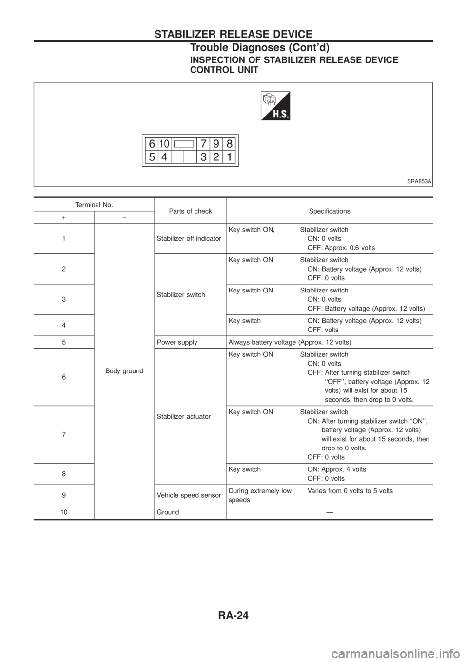
INSPECTION OF STABILIZER RELEASE DEVICE
CONTROL UNIT
Terminal No.
Parts of check Speci®cations
+þ
1
Body groundStabilizer off indicatorKey switch ON, Stabilizer switch
ON: 0 volts
OFF: Approx. 0.6 volts
2
Stabilizer switchKey switch ON Stabilizer switch
ON: Battery voltage (Approx. 12 volts)
OFF: 0 volts
3Key switch ON Stabilizer switch
ON: 0 volts
OFF: Battery voltage (Approx. 12 volts)
4Key switch ON: Battery voltage (Approx. 12 volts)
OFF: volts
5 Power supply Always battery voltage (Approx. 12 volts)
6
Stabilizer actuatorKey switch ON Stabilizer switch
ON: 0 volts
OFF: After turning stabilizer switch
``OFF'', battery voltage (Approx. 12
volts) will exist for about 15
seconds, then drop to 0 volts.
7Key switch ON Stabilizer switch
ON: After turning stabilizer switch ``ON'',
battery voltage (Approx. 12 volts)
will exist for about 15 seconds, then
drop to 0 volts.
OFF: 0 volts
8Key switch ON: Approx. 4 volts
OFF: 0 volts
9 Vehicle speed sensorDuring extremely low
speedsVaries from 0 volts to 5 volts
10 Ground Ð
SRA853A
STABILIZER RELEASE DEVICE
Trouble Diagnoses (Cont'd)
RA-24
Page 1124 of 1226
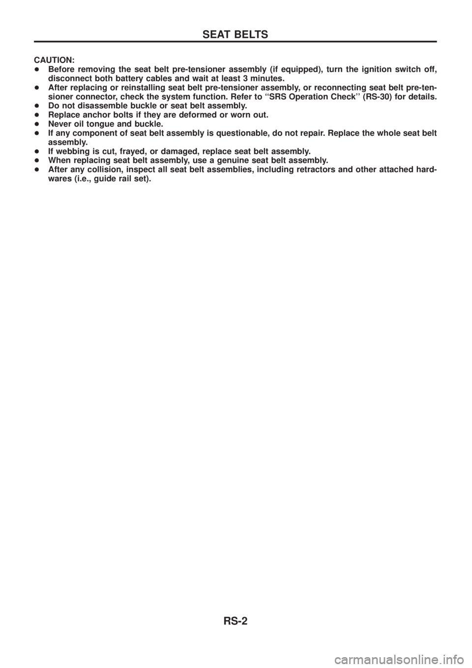
CAUTION:
+Before removing the seat belt pre-tensioner assembly (if equipped), turn the ignition switch off,
disconnect both battery cables and wait at least 3 minutes.
+After replacing or reinstalling seat belt pre-tensioner assembly, or reconnecting seat belt pre-ten-
sioner connector, check the system function. Refer to ``SRS Operation Check'' (RS-30) for details.
+Do not disassemble buckle or seat belt assembly.
+Replace anchor bolts if they are deformed or worn out.
+Never oil tongue and buckle.
+If any component of seat belt assembly is questionable, do not repair. Replace the whole seat belt
assembly.
+If webbing is cut, frayed, or damaged, replace seat belt assembly.
+When replacing seat belt assembly, use a genuine seat belt assembly.
+After any collision, inspect all seat belt assemblies, including retractors and other attached hard-
wares (i.e., guide rail set).
SEAT BELTS
RS-2