2006 NISSAN PATROL battery
[x] Cancel search: batteryPage 799 of 1226
Voltage check method
1. Remove the blown fuse and disconnect all loads (i.e. SW1 open, relay disconnected and solenoid discon-
nected) powered through the fuse.
2. Turn the ignition key to the ON or START position. Verify battery voltage at the B
+side of the fuse ter-
minal (one lead on the B
+terminal side of the fuse block and one lead on a known good ground).
3. With SW1 open and the DMM leads across both fuse terminals, check for voltage.
voltage; short is between fuse block and SW1 (point A).
no voltage; short is further down the circuit than SW1.
4. With SW1 closed, relay and solenoid disconnected and the DMM leads across both fuse terminals, check
for voltage.
voltage; short is between SW1 and the relay (point B).
no voltage; short is further down the circuit than the relay.
5. With SW1 closed, relay contacts jumped with fused jumper wire check for voltage.
voltage; short is down the circuit of the relay or between the relay and the disconnected solenoid
(point C).
no voltage; retrace steps and check power to fuse block.
GROUND INSPECTION
Ground connections are very important to the proper operation of electrical and electronic circuits. Ground
connections are often exposed to moisture, dirt and other corrosive elements. The corrosion (rust) can become
an unwanted resistance. This unwanted resistance can change the way a circuit works.
Electronically controlled circuits are very sensitive to proper grounding. A loose or corroded ground can dras-
tically affect an electronically controlled circuit. A poor or corroded ground can easily affect the circuit. Even
when the ground connection looks clean, there can be a thin ®lm of rust on the surface.
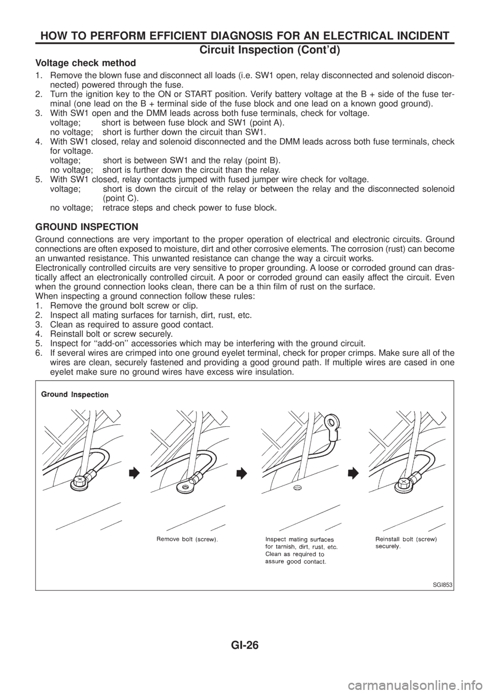
When inspecting a ground connection follow these rules:
1. Remove the ground bolt screw or clip.
2. Inspect all mating surfaces for tarnish, dirt, rust, etc.
3. Clean as required to assure good contact.
4. Reinstall bolt or screw securely.
5. Inspect for ``add-on'' accessories which may be interfering with the ground circuit.
6. If several wires are crimped into one ground eyelet terminal, check for proper crimps. Make sure all of the
wires are clean, securely fastened and providing a good ground path. If multiple wires are cased in one
eyelet make sure no ground wires have excess wire insulation.
SGI853
HOW TO PERFORM EFFICIENT DIAGNOSIS FOR AN ELECTRICAL INCIDENT
Circuit Inspection (Cont'd)
GI-26
Page 800 of 1226
VOLTAGE DROP TESTS
Voltage drop tests are often used to ®nd components or circuits which have excessive resistance. A voltage
drop in a circuit is caused by a resistancewhen the circuit is in operation.
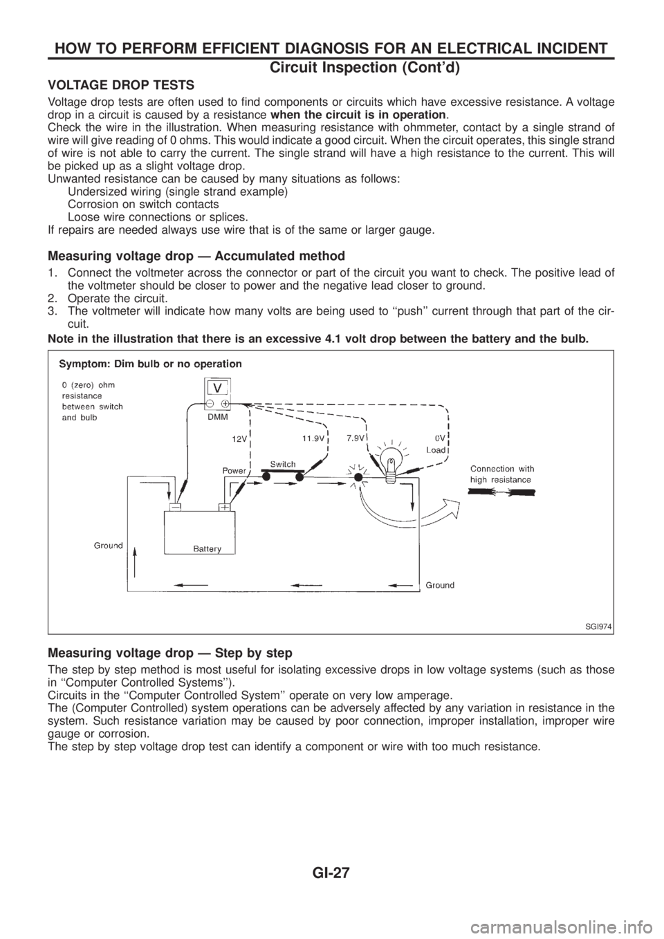
Check the wire in the illustration. When measuring resistance with ohmmeter, contact by a single strand of
wire will give reading of 0 ohms. This would indicate a good circuit. When the circuit operates, this single strand
of wire is not able to carry the current. The single strand will have a high resistance to the current. This will
be picked up as a slight voltage drop.
Unwanted resistance can be caused by many situations as follows:
Undersized wiring (single strand example)
Corrosion on switch contacts
Loose wire connections or splices.
If repairs are needed always use wire that is of the same or larger gauge.
Measuring voltage drop Ð Accumulated method
1. Connect the voltmeter across the connector or part of the circuit you want to check. The positive lead of
the voltmeter should be closer to power and the negative lead closer to ground.
2. Operate the circuit.
3. The voltmeter will indicate how many volts are being used to ``push'' current through that part of the cir-
cuit.
Note in the illustration that there is an excessive 4.1 volt drop between the battery and the bulb.
Measuring voltage drop Ð Step by step
The step by step method is most useful for isolating excessive drops in low voltage systems (such as those
in ``Computer Controlled Systems'').
Circuits in the ``Computer Controlled System'' operate on very low amperage.
The (Computer Controlled) system operations can be adversely affected by any variation in resistance in the
system. Such resistance variation may be caused by poor connection, improper installation, improper wire
gauge or corrosion.
The step by step voltage drop test can identify a component or wire with too much resistance.
SGI974
HOW TO PERFORM EFFICIENT DIAGNOSIS FOR AN ELECTRICAL INCIDENT
Circuit Inspection (Cont'd)
GI-27
Page 803 of 1226
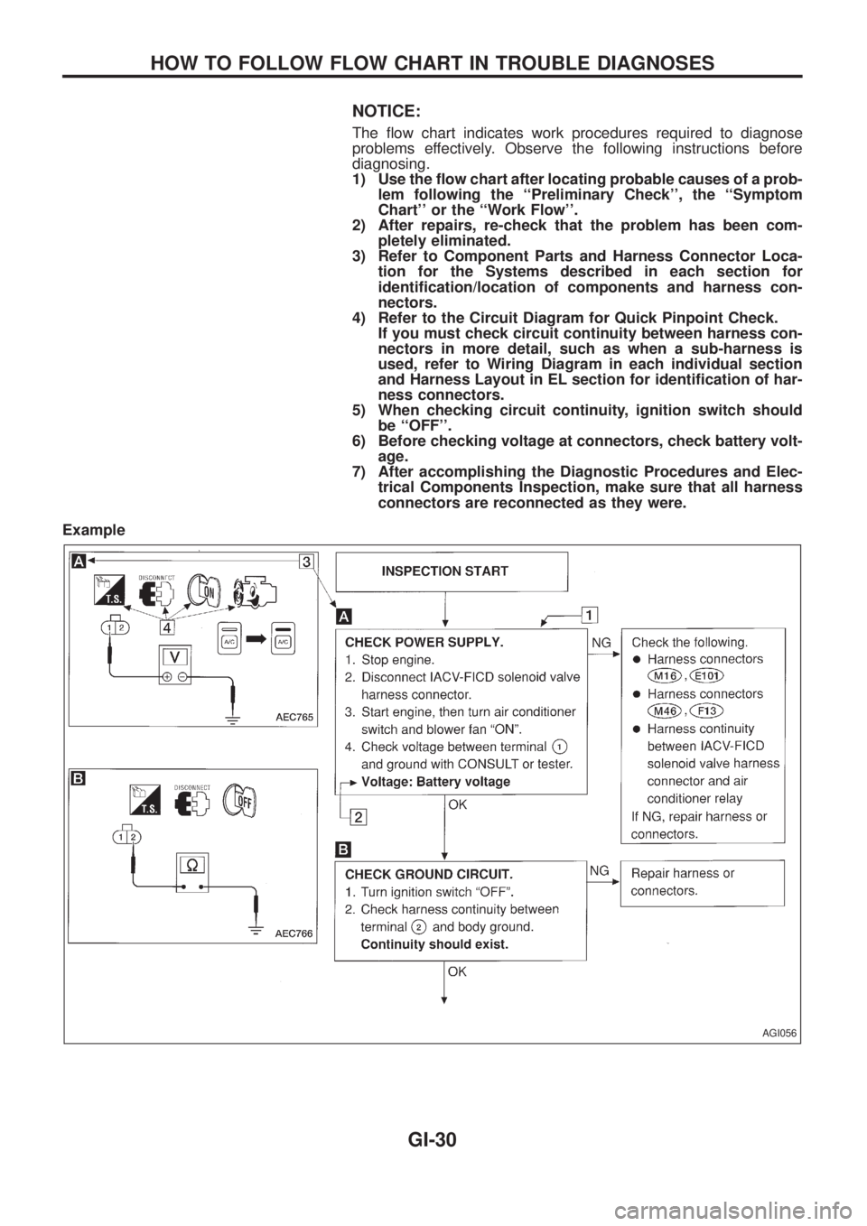
NOTICE:
The ¯ow chart indicates work procedures required to diagnose
problems effectively. Observe the following instructions before
diagnosing.
1) Use the ¯ow chart after locating probable causes of a prob-
lem following the ``Preliminary Check'', the ``Symptom
Chart'' or the ``Work Flow''.
2) After repairs, re-check that the problem has been com-
pletely eliminated.
3) Refer to Component Parts and Harness Connector Loca-
tion for the Systems described in each section for
identi®cation/location of components and harness con-
nectors.
4) Refer to the Circuit Diagram for Quick Pinpoint Check.
If you must check circuit continuity between harness con-
nectors in more detail, such as when a sub-harness is
used, refer to Wiring Diagram in each individual section
and Harness Layout in EL section for identi®cation of har-
ness connectors.
5) When checking circuit continuity, ignition switch should
be ``OFF''.
6) Before checking voltage at connectors, check battery volt-
age.
7) After accomplishing the Diagnostic Procedures and Elec-
trical Components Inspection, make sure that all harness
connectors are reconnected as they were.
Example
AGI056
HOW TO FOLLOW FLOW CHART IN TROUBLE DIAGNOSES
GI-30
Page 804 of 1226
How to Follow This Flow Chart
Work and diagnostic procedure
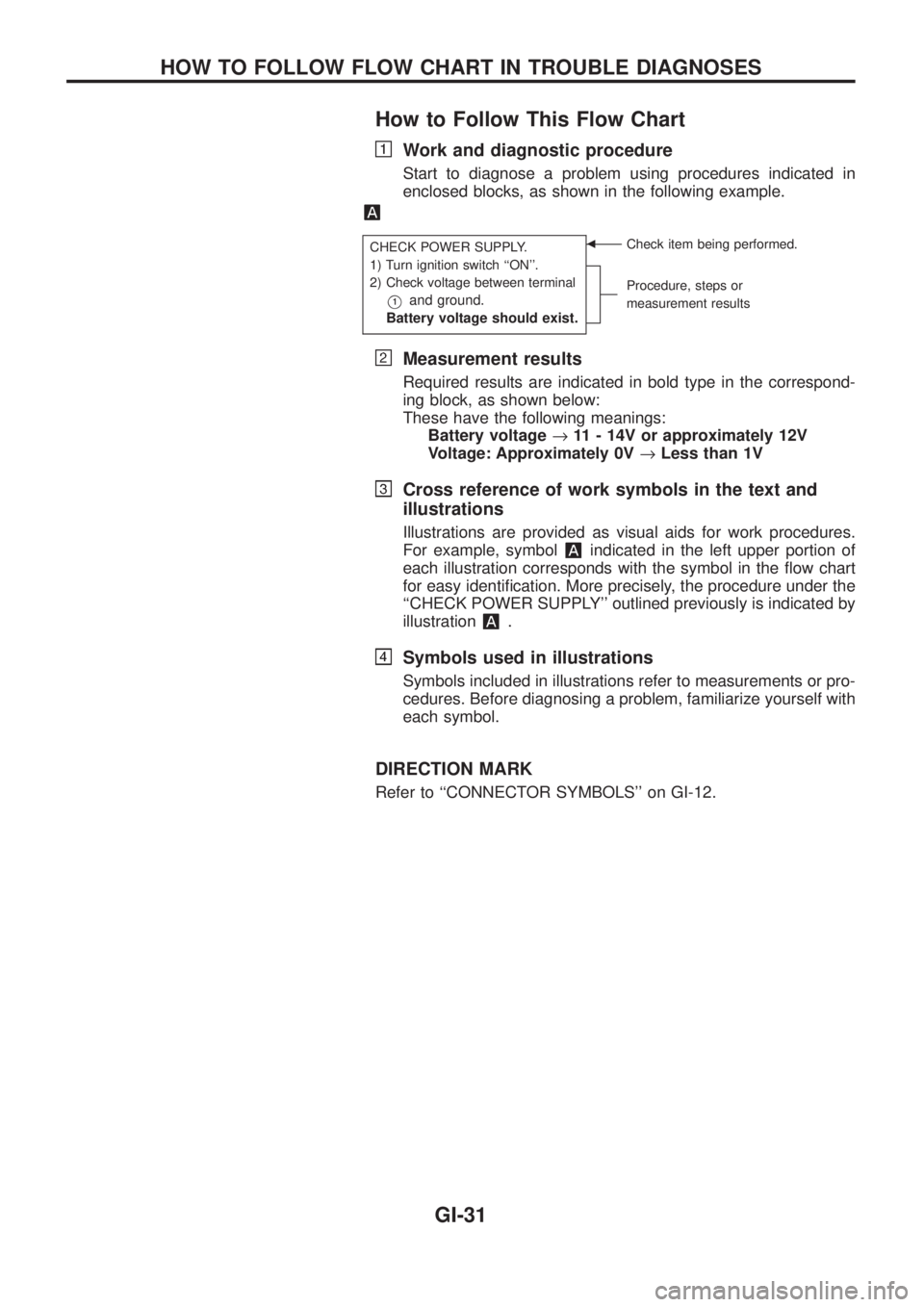
Start to diagnose a problem using procedures indicated in
enclosed blocks, as shown in the following example.
CHECK POWER SUPPLY.
1) Turn ignition switch ``ON''.
2) Check voltage between terminal
V1and ground.
Battery voltage should exist.
bCheck item being performed.
Procedure, steps or
measurement results
Measurement results
Required results are indicated in bold type in the correspond-
ing block, as shown below:
These have the following meanings:
Battery voltage®11 - 14V or approximately 12V
Voltage: Approximately 0V®Less than 1V
Cross reference of work symbols in the text and
illustrations
Illustrations are provided as visual aids for work procedures.
For example, symbol
indicated in the left upper portion of
each illustration corresponds with the symbol in the ¯ow chart
for easy identi®cation. More precisely, the procedure under the
``CHECK POWER SUPPLY'' outlined previously is indicated by
illustration
.
Symbols used in illustrations
Symbols included in illustrations refer to measurements or pro-
cedures. Before diagnosing a problem, familiarize yourself with
each symbol.
DIRECTION MARK
Refer to ``CONNECTOR SYMBOLS'' on GI-12.
HOW TO FOLLOW FLOW CHART IN TROUBLE DIAGNOSES
GI-31
Page 805 of 1226
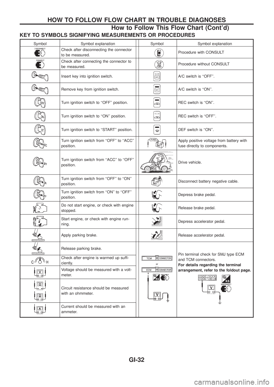
KEY TO SYMBOLS SIGNIFYING MEASUREMENTS OR PROCEDURES
Symbol Symbol explanation Symbol Symbol explanation
Check after disconnecting the connector
to be measured.Procedure with CONSULT
Check after connecting the connector to
be measured.Procedure without CONSULT
Insert key into ignition switch.A/C switch is ``OFF''.
Remove key from ignition switch.A/C switch is ``ON''.
Turn ignition switch to ``OFF'' position.REC switch is ``ON''.
Turn ignition switch to ``ON'' position.REC switch is ``OFF''.
Turn ignition switch to ``START'' position.DEF switch is ``ON''.
Turn ignition switch from ``OFF'' to ``ACC''
position.Apply positive voltage from battery with
fuse directly to components.
Turn ignition switch from ``ACC'' to ``OFF''
position.Drive vehicle.
Turn ignition switch from ``OFF'' to ``ON''
position.Disconnect battery negative cable.
Turn ignition switch from ``ON'' to ``OFF''
position.Depress brake pedal.
Do not start engine, or check with engine
stopped.Release brake pedal.
Start engine, or check with engine run-
ning.Depress accelerator pedal.
Apply parking brake.Release accelerator pedal.
Release parking brake.
Pin terminal check for SMJ type ECM
and TCM connectors.
For details regarding the terminal
arrangement, refer to the foldout page.Check after engine is warmed up suffi-
ciently.
Voltage should be measured with a volt-
meter.
Circuit resistance should be measured
with an ohmmeter.
Current should be measured with an
ammeter.
HOW TO FOLLOW FLOW CHART IN TROUBLE DIAGNOSES
How to Follow This Flow Chart (Cont'd)
GI-32
Page 806 of 1226
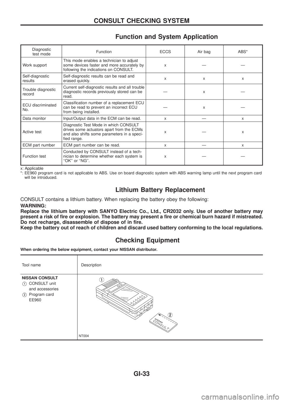
Function and System Application
Diagnostic
test modeFunction ECCS Air bag ABS*
Work supportThis mode enables a technician to adjust
some devices faster and more accurately by
following the indications on CONSULT.xÐÐ
Self-diagnostic
resultsSelf-diagnostic results can be read and
erased quickly.xxx
Trouble diagnostic
recordCurrent self-diagnostic results and all trouble
diagnostic records previously stored can be
read.ÐxÐ
ECU discriminated
No.Classi®cation number of a replacement ECU
can be read to prevent an incorrect ECU
from being installed.ÐxÐ
Data monitor Input/Output data in the ECM can be read. x Ð x
Active testDiagnostic Test Mode in which CONSULT
drives some actuators apart from the ECMs
and also shifts some parameters in a speci-
®ed range.xÐx
ECM part number ECM part number can be read. x Ð x
Function testConducted by CONSULT instead of a tech-
nician to determine whether each system is
``OK'' or ``NG''.xÐÐ
x: Applicable
*: EE960 program card is not applicable to ABS. Use on board diagnostic system with ABS warning lamp until the next program card
will be introduced.
Lithium Battery Replacement
CONSULT contains a lithium battery. When replacing the battery obey the following:
WARNING:
Replace the lithium battery with SANYO Electric Co., Ltd., CR2032 only. Use of another battery may
present a risk of ®re or explosion. The battery may present a ®re or chemical burn hazard if mistreated.
Do not recharge, disassemble of dispose of in ®re.
Keep the battery out of reach of children and discard used battery conforming to the local regulations.
Checking Equipment
When ordering the below equipment, contact your NISSAN distributor.
Tool name Description
NISSAN CONSULT
V1CONSULT unit
and accessories
V2Program card
EE960
NT004
CONSULT CHECKING SYSTEM
GI-33
Page 889 of 1226
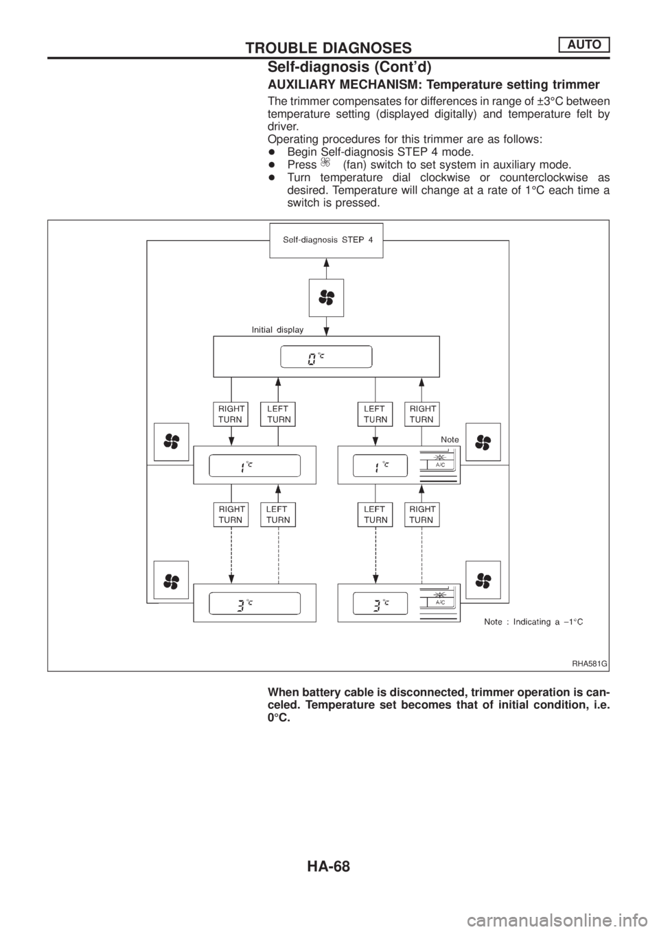
AUXILIARY MECHANISM: Temperature setting trimmer
The trimmer compensates for differences in range of 3ÉC between
temperature setting (displayed digitally) and temperature felt by
driver.
Operating procedures for this trimmer are as follows:
+Begin Self-diagnosis STEP 4 mode.
+Press
(fan) switch to set system in auxiliary mode.
+Turn temperature dial clockwise or counterclockwise as
desired. Temperature will change at a rate of 1ÉC each time a
switch is pressed.
When battery cable is disconnected, trimmer operation is can-
celed. Temperature set becomes that of initial condition, i.e.
0ÉC.
RHA581G
TROUBLE DIAGNOSESAUTO
Self-diagnosis (Cont'd)
HA-68
Page 949 of 1226
A
A/C HFC134a (R134a) system service
procedure ..................................................HA-112
A/C HFC134a system service equip-
ment precaution ............................................HA-9
A/C air ¯ow .....................................................HA-13
A/C component layout ....................................HA-12
A/C compressor precaution..............................HA-6
A/C compressor special service tool ...........HA-6, 7
A/C control linkage adjustment (auto
A/C).............................................................HA-77
A/C control operation (manual A/C) ...............HA-16
A/C harness layout (manual A/C) ..................HA-17
A/C lubricant (R134a) ...................................HA-114
A/C relay.........................................................HA-97
A/C self-diagnoses (auto A/C)........................HA-63
A/CCUT - Wiring diagram ............................EC-186
A/T control ....................................................EC-174
ABS sensor rotor ............................................FA-15
ACC/SW - Wiring diagram ...........................EC-105
ACL/SW - Wiring diagram ............................EC-164
ADJRES - Wiring diagram .............................EC-91
APS - Wiring diagram ..................................EC-138
AT/C - Wiring diagram..................................EC-174
AUDIO - Wiring diagram ...............................EL-168
Accelerator position sensor ..........................EC-138
Accelerator position switch...........................EC-164
Accelerator switch (F/C) ...............................EC-105
Adjustment resistor.........................................EC-91
Air bag disposal..............................................RS-17
Air bag ..............................................................RS-8
Air bleeding (hydraulic clutch) ..........................CL-6
Air bleeding for brake system ..........................BR-4
Air cleaner ®lter replacement .........................MA-18
Air conditioner cut control ..............................EC-19
Air ¯ow meter - See Mass air ¯ow
sensor .........................................................EC-73
Air mix door control linkage
adjustment ................................................HA-81
Alternator.........................................................EL-56
Antenna - See Power antenna .....................EL-181
Audio and A/C control removal and
installation - See Instrument panel .............BT-11
Audio .............................................................EL-168
Auto lock free running hub .............................FA-13
Automatic ampli®er .........................................HA-61
Axle housing (rear) ...........................................RA-9
B
BACK/L - Wiring diagram................................EL-78
Back door opener - See Back door ..................BT-6
Back door trim.................................................BT-24
Back door window...........................................BT-45
Back door ..........................................................BT-6Back-up lamp switch (M/T) ..............................MT-4
Back-up lamp ..................................................EL-78
Battery .............................................................EL-37
Baulk ring (M/T)..............................................MT-10
Body alignment ...............................................BT-49
Body mounting ................................................BT-48
Brake booster .................................................BR-15
Brake ¯uid change ...........................................BR-3
Brake ¯uid level and line check .......................BR-3
Brake ¯uid level .............................................MA-23
Brake hydraulic line ..........................................BR-5
Brake inspection ............................................MA-24
Brake master cylinder ....................................BR-12
Brake pedal ....................................................BR-10
Bulb speci®cations ........................................EL-314
Bumper, front ................................................... BT-4
Bumper, rear .....................................................BT-6
C
CD/CHG - Wiring diagram ............................EL-176
CHIME - Wiring diagram...............................EL-136
CIGAR - Wiring diagram ...............................EL-156
CKPS - Wiring diagram ................................EC-143
CLOCK - Wiring diagram ..............................EL-157
CMPS - Wiring diagram .................................EC-68
COMPAS - Wiring diagram ...........................EL-117
CONSULT for ECCS ......................................EC-36
CONSULT general information ........................GI-33
COOL/F - Wiring diagram ............................EC-112
CSPS - Wiring diagram ..................................EC-86
Cab body.........................................................BT-47
Camshaft inspection ......................................EM-36
Camshaft position sensor (PUMP).................EC-68
Center case (Transfer) ....................................TF-10
Charge air cooler fan control .......................EC-177
Charge air temperature sensor ....................EC-121
Chassis and body maintenance ....................MA-20
Cigarette lighter.............................................EL-156
Circuit breaker.................................................EL-14
Clock .............................................................EL-157
Clutch booster...................................................CL-9
Clutch cover ....................................................CL-14
Clutch damper ..................................................CL-7
Clutch disc ......................................................CL-13
Clutch ¯uid level.............................................MA-20
Clutch master cylinder ......................................CL-7
Clutch operating cylinder ..................................CL-8
Clutch pedal ......................................................CL-5
Clutch release bearing ....................................CL-11
Clutch release mechanism .............................CL-11
Clutch withdrawal lever ...................................CL-11
Coil spring (front) ............................................FA-25
Coil spring (rear) ............................................RA-14
Collision diagnosis..........................................RS-45
Combination meter removal and instal-
lation - See Instrument panel ......................BT-11
ALPHABETICAL INDEX
IDX-2