2006 MITSUBISHI COLT ABS
[x] Cancel search: ABSPage 209 of 364
TECHNICAL FEATURES
GENERAL00-24
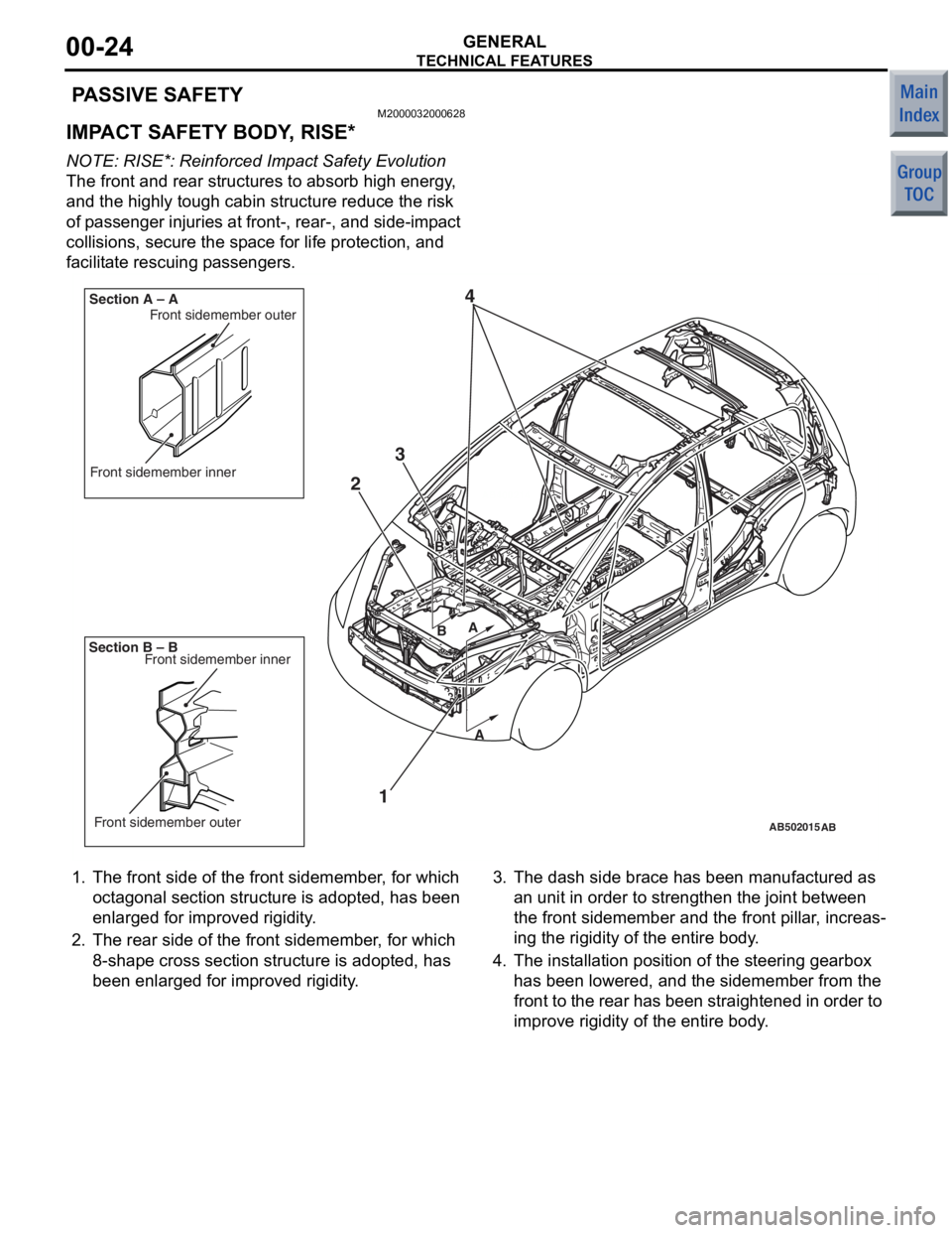
PASSIVE SAFETY
M2000032000628
IMPACT SAFETY BODY, RISE*
NOTE: RISE*: Reinforced Impact Safety Evolution
The front and rear structures to absorb high energy,
and the highly tough cabin structure reduce the risk
of passenger injuries at front-, rear-, and side-impact
collisions, secure the space for life protection, and
facilitate rescuing passengers.
AB201266
AB201267AB502015
AB400214
AB
1
2
4
Front sidemember inner
Front sidemember outer
B AA
B
Section B – B Section A – A
Front sidemember inner
Front sidemember outer
3
1.
The front side of the front sidemember , for which
oct agonal section structure is a dopted, has been
enlarged for improved rigidity .
2.The rear side o f the fro nt sidememb er, for which
8-shape cross section structu re is adop ted, has
bee n enlarged f or improved rig idit y.
3. The dash side brace ha s been manufactured a s
an unit in ord er to strength en the joint betwee n
the front side member and the front pillar , increas
-
in g the rigid ity of the e ntire body .
4.The inst allation po sition o f the steering gea rbox
has bee n lowere d, and the sidememb er from the
fron t to the re ar has been straigh tened in orde r to
improve rig idit y of t he ent ire body.
Page 212 of 364
TECHNICAL FEATURES
GENERAL00-27
POWER WINDOW WITH SAFETY MECHA-
NISM
The power window with safety mechanism has been
adopted to automatically roll down and stop the door
window glass as soon as the occurrence of jamming
is detected at the time of rolling up the door window
glass.
SUNROOF WITH SA FETY MECHANISM
The sunroof with safe ty mechanism has been
adopted so that the roof lid glass can move in the
reverse direction and stop when application of exter
-
nal force hinders the movement during the sliding to
close or tilt down operation.
TRIMS AND HEADLINING
The head impact absorption structure has been
adopted for the pillar trim, quarter trim, and headlin
-
ing so that impact towards the head of a passenger
can be reduced.
OTHER SAFETY FEATURES
•3-point ELR seat belts
•Child-protection rear door locks
•Front fog lamps
EQUIPMENTSM2000026000221
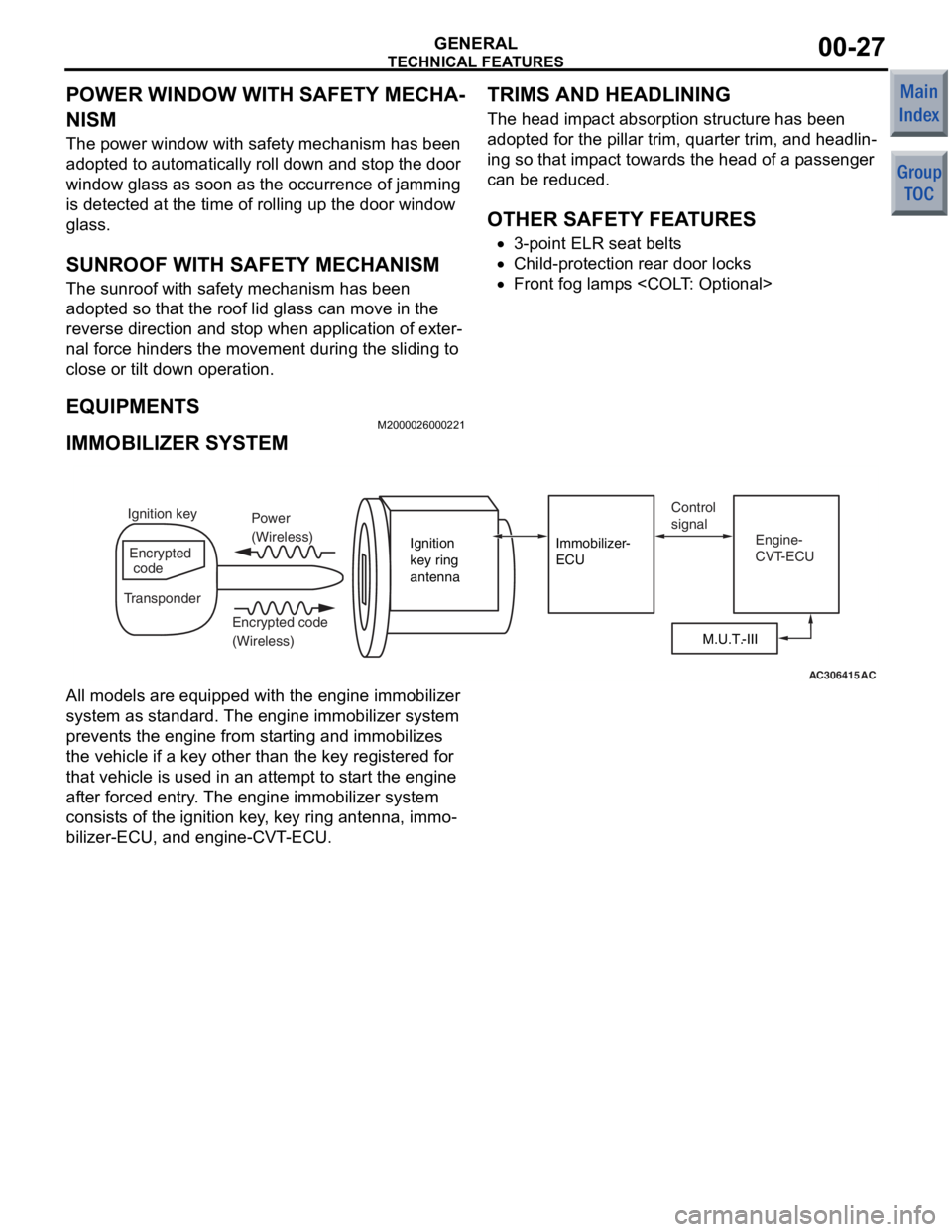
IMMOBILIZER SYSTEM
AC306415AC
M.U.T.-III
Ignition
key ring
antenna
Immobilizer-
ECU
Ignition key
Encrypted
code
Transponder Power
(Wireless)
Encrypted code
(Wireless) Control
signal
Engine-
CVT-ECU
All models are equipped with the e ngine immobilizer
system as st andard. The en gine immobilizer syst em
preve nts the engin e from starting and immobilizes
the vehicle if a key o ther tha n the key registered for
that vehicle is used in an attempt to start the e ngine
af te r forced entry . The en gine immobilizer syst em
consist s of the ignition key, key ring antenna, immo
-
bilizer-ECU, and engine-CVT-ECU.
Page 213 of 364

TECHNICAL FEATURES
GENERAL00-28
ENVIRONMENTAL PROTECTION
M2000027000279
Mitsubishi has given careful consideration to protec-
tion of natural resources and the environment in the
vehicle. Environmentally friendly features are shown
below.
IMPROVEMENT ON RECYCLING EFFICIENCY
ClassificationMain Components
Components made
of recycled
materialsChip materials produced during manufacturing process has been reused as the
following components: Door inside handle, bu mper, radiator grille, instrument panel,
door trims, or floor padding.
Waste materials produced by other i ndustries have been reused as the following
components: Engine oil level gauge, air filter casing, and sound absorbing materials
for dash panel
Components made
of materials which
can be easily
recycledThermoplastic resin has been utilised as the following components: Inside door
handle, bumper, radiator grille, instrument panel, door trim
Thermoplastic resin has been utilised as t he following components: Vacuum hose for
engine control, air intake hose, hood weather strip, tailgate opening weather strip
REDUCTION OF MATERIAL BURDEN ON ENVIRONMENT
ItemMain Components
Elimination of
environmental
burden materialsLead-free materials have been utilised as the following components: Radiator, fuel
tank, power steering oil pressure hose, el ectrodeposition paint for body, glass ceramic
print, heater core, battery terminals, wiring harness
Non-asbestos material has been used for engine gaskets.
PVC(polyvinyl chloride)-free materials ha ve been used for the waterproofing film.
Prevention of
ozone depletionAir conditioner filled with new refrigerant (HFC 134a) has been installed.
Prevention of air
pollutionEmployment of a metal cylinder head gasket reduces the volume of incomplete
combustion generated between the cylinder block and cylinder head, and suppresses
the level of unburned hydrocarbon (HC).
SERVICEABILITY AND RELIABILITY
M2000028000528
MULTI USE TESTER-III (M.U.T.-III) SUB
ASSEMBLY
Comprehensive improvements have been made to
the M.U.T.-II, a tester for diagnosing problems with
the electronic control system. For easier servicing,
the newly developed M.U.T.-III has greatly improved
functions and is much easier to use. The M.U.T.-III
expands the functions of the M.U.T.-II in the following
ways:
1.CAN* bus diagnosis
•Auto diagnosis function for the CAN commu-
nications bus line is added.
NOTE: *CAN: Controller Area Network (for further
details, refer to GROUP 54C
P.54C-2).
Page 219 of 364
GENERAL INFORMATION
POWER PLANT MOUNT32-2
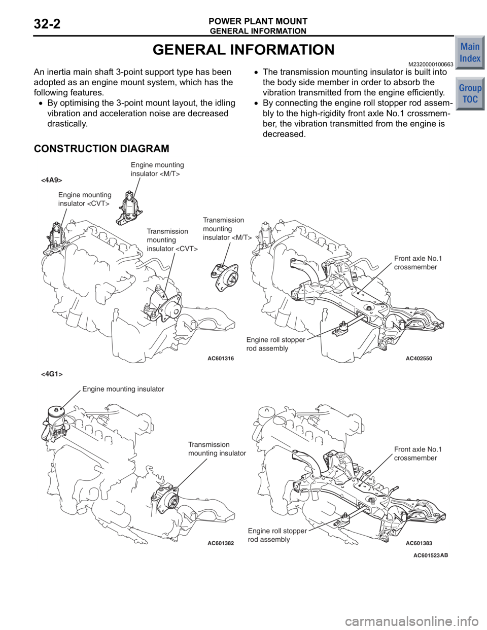
GENERAL INFORMATION
M2320000100663
An inertia main shaft 3-point support type has been
adopted as an engine mount system, which has the
following features.
•By optimising the 3-point mount layout, the idling
vibration and acceleration noise are decreased
drastically.
•The transmission mounting insulator is built into
the body side member in order to absorb the
vibration transmitted from the engine efficiently.
•By connecting the engine roll stopper rod assem-
bly to the high-rigidity front axle No.1 crossmem-
ber, the vibration transmitted from the engine is
decreased.
CONSTRUCTION DIAGRAM
AC601523
AC402550
AC601316
AC601382AC601383
<4A9>
<4G1>
AB
Engine mounting
insulator
mounting
insulator
Transmission
mounting insulator Front axle No.1
crossmember
Front axle No.1
crossmember
Engine roll stopper
rod assembly
Engine mounting
insulator
Transmission
mounting
insulator
Engine roll stopper
rod assembly
Page 235 of 364

GENERAL INFORMATION
POWER STEERING37-2
GENERAL INFORMATION
M2370000100851
Electric power steering system has been adopted for
all models in order to ensure an optimised steering
feeling.
FEATURES
•Improved fuel consumption by reduction of
engine load, and weight saving by decrease of
the number of parts have been achieved with the
introduction of the electric power steering system.
•3-spoke type steering wheel integrated with an
SRS airbag has been adopted.
•Impact-absorbing mechanism and tilt steering
mechanism have been adopted.
SPECIFICATIONS
ItemSpecifications
Vehicles with
14-inch wheelsVehicles with
15-inch wheelsVehicles with
16-inch wheels
Steering wheelTy p e3-spoke type
Outside diameter mm370
Maximum number of turns3.43.22.6
Steering columnColumn mechanismShock absorbing mechanism and tilt steering
mechanism
Power steering typeElectric powered type
Steering gearTy p eRack and pinion
Stroke ratio (Rack
stroke/Steering wheel
maximum turning radius)44.1550.46
Rack stroke mm150143130
Steering angleInner wheel41 ° 40’39 ° 00’34 ° 10’
Outer wheel35 ° 30’33 ° 40’30 ° 00’
Page 238 of 364
CONSTRUCTION DESCRIPTION
POWER STEERING37-5
CONSTRUCTION DESCRIPTION
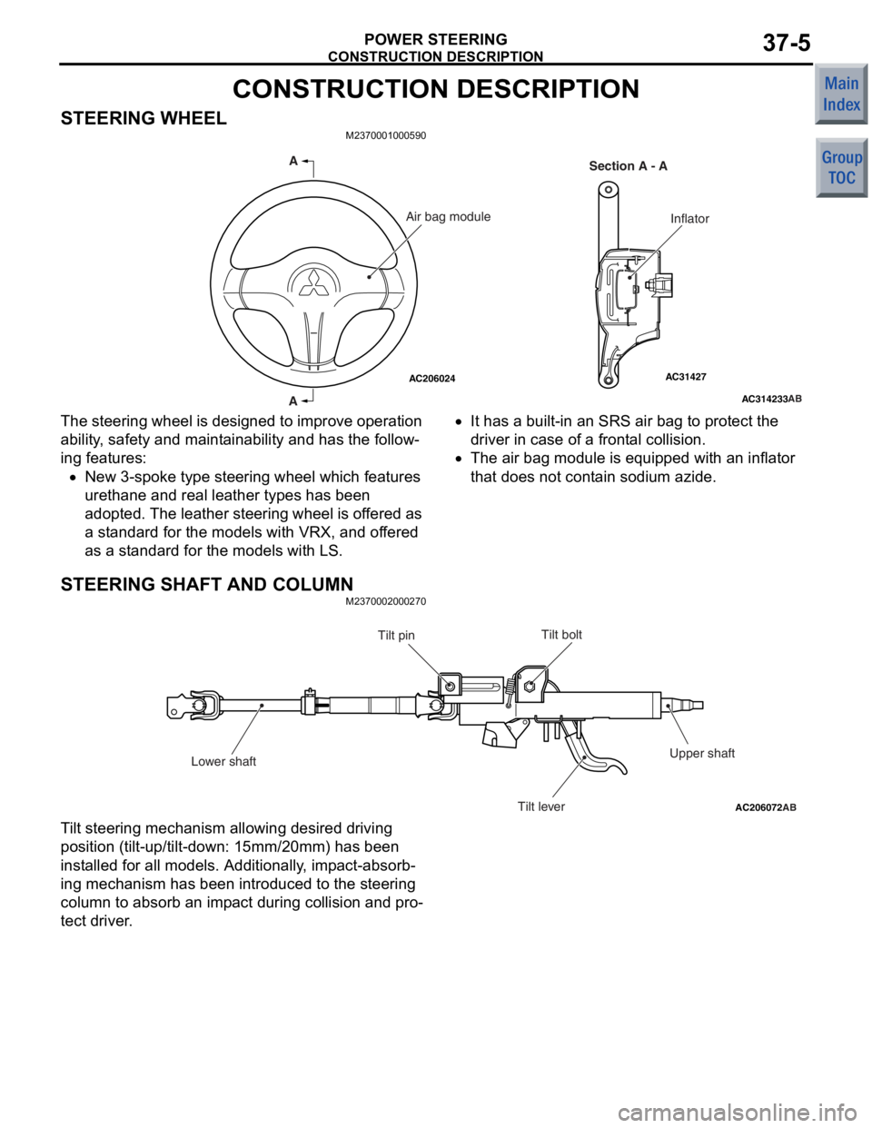
STEERING WHEELM2370001000590
AC314233
AC31427AC206024AB
A
A Section A - A
InflatorAir bag module
The steering wh
eel is de sig ned to impro v e operat ion
ability
, safety and main t a inabilit y and has the follow
-
ing features:
•New 3-spoke type stee ring whe e l which fe atures
uret
hane a nd real lea t her types has been
ado
pted. The leather stee ring wh eel is o f fere d as
a st
a ndard f o r the models with VRX, and of fered
as a st
an dard for the models with LS.
•It ha s a built-in a n SRS a i r ba g to pro t ect t he
driv
er in c a s e of a front a l c o ll is i o n.
•The air b ag mo dule is equip ped wit h an inflat or
tha
t does not cont ain sod i um azide.
STEERING SHAFT AND COLUMN
M23700020 0027 0
AC206072AB
Tilt bolt
Tilt pin
Lower shaft Tilt leverUpper shaft
T
i lt steering mecha n ism allowing desired d r iving
position
(tilt -up/tilt-down: 1 5 mm/20mm) ha s be en
inst
alled for all mo dels. Additiona lly , imp a ct-absorb
-
ing mechanism h a s be en in troduced to the steering
colu
mn t o absorb an imp a ct during collision an d pro
-
te c t dri v er .
Page 239 of 364
CONSTRUCTION DESCRIPTION
POWER STEERING37-6
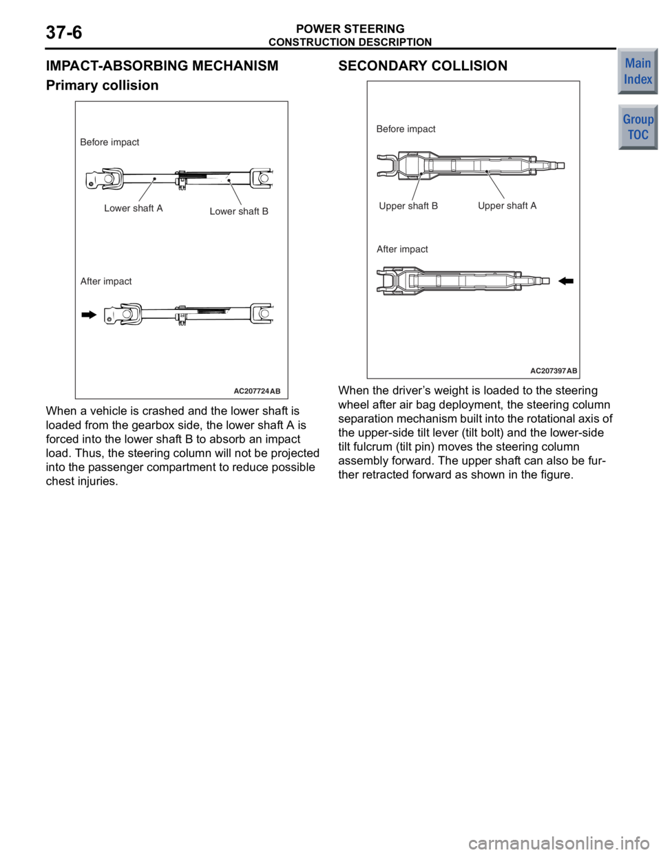
IMPACT-ABSORBING MECHANISM
Primary collision
AC207724AB
Lower shaft ALower shaft B
After impact
Before impact
When a
vehicle is crashed a nd the lower shaf t is
loade
d from the g earbox side, the lower shaf t A is
forced
into the lower sha f t B t o absorb an imp a ct
load.
Thus, the steering column will not be projecte d
into t
he p a ssenge r comp artme n t to red u ce possible
chest in
jurie s .
SECONDARY COLLISION
AC207397AB
Upper shaft B
Before impact
After impact Upper shaft A
When th
e driver ’ s we ight is loaded to the stee ring
wh
eel a f ter air ba g deployment, the steerin g co lumn
sep
a ration mechanism built into the rot a tiona l a x is of
the upp
er-side tilt lever (t ilt b o lt) a nd the lower-side
tilt
fulcrum (t ilt p i n) move s the stee ring colu mn
assembly fo
rwa r d. The upper shaf t can also b e fur
-
ther retrac ted forward as sh own in the figure.
Page 241 of 364
ELECTRICAL POWER STEERING
POWER STEERING37-8
ELECTRICAL PARTS AND FUNCTIONS
Parts nameDescription about function
SensorVehicle speed sensor (ABS-ECU)Sends the vehicle speed signal to the electric power
steering-ECU.
Torque sensorDetects a steering force, converts it into the voltage signal,
and then sends the signal to the electric power
steering-ECU.
ActuatorMotorGenerates assist torque by the steering operation to the
steering gear using the signals sent from the electric power
steering-ECU.
Electric power steering warning
lampWarns a driver of the system malfunction using the signal
sent from the electric power steering-ECU.
Electric power steering-ECUControl the actuator (motor) based on the signal sent from
sensor.
Controls the self-diagnostic fu nction and fail-safe function.
Controls diagnostic function (Compatible with M.U.T.-III).
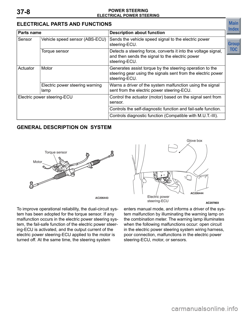
GENERAL DESCRIPTION ON SYSTEM
AC207803
AC206444
AC206443
AB
Electric power
steering-ECU
Glove box
Torque sensor
Motor
T o improve opera t iona l reliabi lity , th e dual-circuit sys-
tem ha s be en ad opted f o r the t o rque sensor . If a n y
malfunct
i on occurs in the electric power st eering sys
-
tem, the fail-sa f e fun c tio n of th e ele c tric power steer-
ing-ECU is activated, and the ou tput current of the
electric power steerin
g-ECU a pplied to the motor is
turned o
f f. At th e sa me time, the steerin g syste m enters man ual mode, and informs a dr iver of the sys
-
tem malfu
n ction by illuminating th e warnin g lamp on
the
comb in at io n me te r . Th e warn in g la mp il lu min a te s
wh
en the following malfu n ct ions occur: ope n circuit
in the
e l ectric power stee ring system wiring harness,
poor connectio
n , ma lfunction s in the e l ectric power
steering-ECU, mo
tor , or sensors.