2006 MITSUBISHI COLT ABS
[x] Cancel search: ABSPage 130 of 364

DIAGNOSIS SYSTEM
MULTIPOINT FUEL INJECTION (MPI) <4G1>13B-16
P0500Vehicle speed sensor systemOpen circuit or short-circuit in
sensor-related circuitsON
P0513Immobilizer malfunctionOpen circuit or short-circuit in
sensor-related circuits−
P0603EEPROM malfunctionAbnormality in engine-ECU−
P0606Engine-ECU main processor
malfunctionAbnormality in engine-ECUON
P0622Alternator FR terminal systemOpen circuit or short-circuit in
system-related circuits−
P0638Throttle valve control servo circuit
range/performance problemAbnormal throttle valve control
servoON
P0642Throttle position sensor power
supply malfunctionOpen circuit or short-circuit in
sensor-related circuitsON
P0657Throttle valve control servo relay
circuit malfunctionOpen circuit or short-circuit in
sensor-related circuitsON
P1021Oil feeder control valve systemOpen circuit and short-circuit in
solenoid valve-related circuits−
P1231Trustful check active stability
control (ASC)ABS/ASC-ECU−
P1233Trustful check throttle position
sensor (main)Abnormality in throttle position
sensor (main)ON
P1234Trustful check throttle position
sensor (sub)Abnormality in throttle position
sensor (sub)ON
P1235Trustful check air flow sensorAbnormality in air flow sensorON
P1236A/D converter systemAbnormality in engine-ECUON
P1237Trustful check accelerator pedal
position sensorAbnormality in accelerator pedal
position sensorON
P1238Air flow sensor trustful for torque
monitoringAbnormality in engine-ECUON
P1239Trustful check engine speedAbnormality in engine-ECUON
P1240Trustful check ignition angleAbnormality in ABS/ASC-ECU−
P1241Torque monitoringAbnormality in engine-ECUON
P1602Communication malfunction
(between engine-ECU main
processor and system LSI)Abnormality in engine-ECUON
P1603Battery back-up circuit malfunctionOpen circuit or short-circuit in
system-related circuitsON
P2100Throttle valve control servo circuit
(open)Open circuit in throttle valve control
servo-related circuitON
P2101Throttle valve control servo
magneto malfunctionShort-circuit in system-related
circuitsON
P2108Throttle valve control servo
processor malfunctionAbnormality in engine-CVT-ECUON
Code No. Diagnosis item Main diagnosis contents Engine
warning lamp
Page 137 of 364

GROUP 35
SERVICE BRAKE
CONTENTS
BASIC BRAKE SYSTEM . . . . . . . . . . . . . . . . . . . . . . . . . . . . . .35A
ANTI-SKID BRAKE SYSTEM (ABS) . . . . . . . . . . . . . . . . . . . . .35B
ACTIVE STABILITY CONTROL SYSTEM (ASC). . . . . . . . . . . .35C
Page 140 of 364

STRUCTURE
CONTROLLER AREA NETWORK (CAN)54C-3
STRUCTURE
M2542000200383
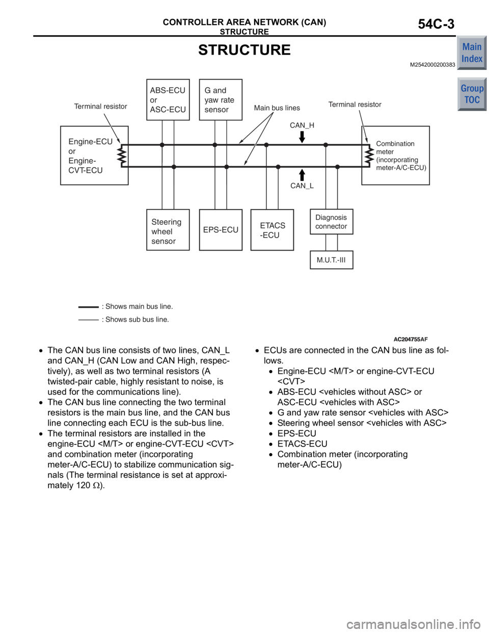
AC204755AC204755AF
Engine-ECU
or
Engine-
CVT-ECUEPS-ECU
M.U.T.-III
ETACS
-ECU
ABS-ECU
or
ASC-ECU
Steering
wheel
sensor G and
yaw rate
sensor
CAN_H
CAN_L Diagnosis
connector
Combination
meter
(incorporating
meter-A/C-ECU)
: Shows sub bus line. : Shows main bus line. Terminal resistor
Terminal resistor Main bus lines
•The CAN bu s line consist s of two lines, CAN_L
and
CAN_H (CAN Low and CAN Hig h , respec
-
tively), as well as two terminal re sistors (A
twisted-p
a ir cable, highly resist ant to noise, is
used for
the communicatio n s line) .
•The CAN bu s line connectin g the two terminal
resist
ors is th e main bus line, an d the CAN bus
line connecting
each ECU is th e su b-bus lin e.
•The terminal resistors are inst alled in the
eng
ine-ECU
and
combin ation mete r (incorpora t ing
meter-A/C-ECU) to st
abi lize co mmunicatio n sig
-
nals (The terminal resist ance is se t at ap proxi-
mately 120 Ω).
•ECUs are conn ected in th e CAN bus line as fo l-
lows.
•En gine -ECU
•ABS-ECU
A
S C-ECU
•G and ya w ra te se nsor
•St e e ring wh eel sensor
•EPS-ECU
•E T ACS-ECU
•Co mbinatio n me ter (in c orpo rating
meter-A/C-ECU)
Page 147 of 364

MAIN BODY
BODY42-4
•RISE (Reinforced Impact Safety Evolution) has
been adopted for the main body in order to
ensure all-round impact safety at high level.
•The use range of rust-resistant steel plates has
been expanded and high strength steel plates
have been optimally arranged. In addition,
rust-resistant steel plates are adopted for items
such as the hood, doors, inner panels of tailgate,
and reinforcements in order to improve the rust
resistance of the main body and to reduce its
weight.
•Sealer has been applied to the entire folded area
of the flanges for the doors, hood, and tailgate in
order to improve rust resistance.
BODY SHELL
M2420003000651
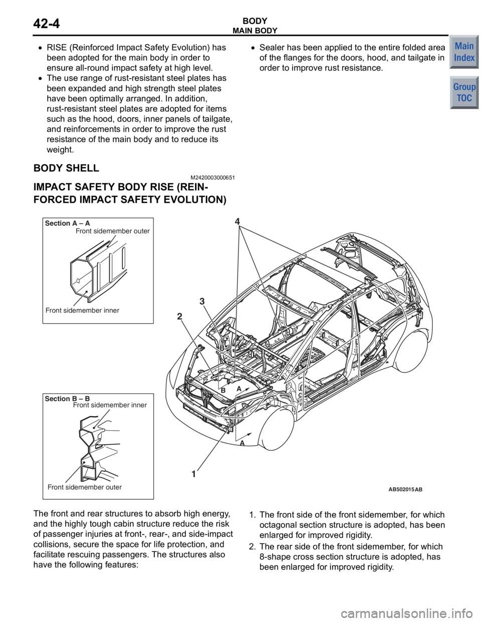
IMPACT SAFETY BODY RISE (REIN-
FORCED IMPACT SAFETY EVOLUTION)
AB201266
AB201267AB502015
AB400214
AB
1
2
4
Front sidemember inner
Front sidemember outer
B AA
B
Section B – B Section A – A
Front sidemember inner
Front sidemember outer
3
The fron
t and re ar st ructure s to abso r b hig h ener gy ,
and the
high ly tough cabin str u cture reduce the risk
of p
a ssenger inju ries at fron t-, rear-, and side-imp a ct
collisions, se
cure the sp a c e fo r life protection , and
facilit
ate rescuing p a sse ngers. The structures also
have
the followin g feat ures:1.The front side of the front sidemember , for wh ich
oct a gonal section stru cture is a dopted , has been
enlarged for improved rigidity .
2.The rear side o f the fr ont sidememb e r , for which
8-shape cross section struct ure is adop ted, ha s
bee n enlarged for improved rig i dity .
Page 162 of 364

WINDOW GLASS
BODY42-19
STRUCTURAL DESCRIPTION
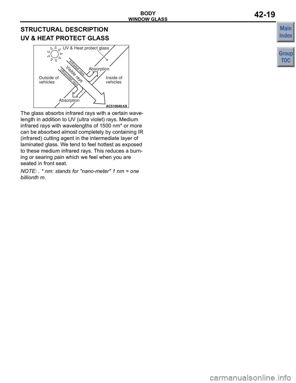
UV & HEAT PROTECT GLASS
AC510040AB
UV & Heat protect glass
Outside of
vehicles Inside of
vehicles
Infrared rays
Ultraviolet rays
Absorption
AbsorptionVisible rays
The glass absorbs infrare d rays with a ce rt ain wave-
length in a ddition to UV (u ltra violet) rays. Medium
infrare
d rays with wa velengths of 15 00 nm* or mo re
can
be absorbed almost comple tely by cont aining IR
(infrare
d) cu tting agent in the inte rmediate layer of
laminate
d gla ss. W e te nd to f eel h o ttest as expo sed
to these medium in
frared ra ys. This reduces a burn
-
ing or searing p a in which we feel when you ar e
seate
d in front seat.
NOTE: . * nm: stand s for "nano-meter" 1 nm = one
billiont
h m.
Page 174 of 364

DIAGNOSIS SYSTEM
CHASSIS ELECTRICAL54A-3
DIAGNOSIS SYSTEM
M2540001000472
For improved serviceability, a diagnosis connector
for M.U.T.-III inspection is built into the instrument
panel near the position of the driver's left foot.
Diagnostic
FunctionMPIABS or
ASCCVTEPSCombination meterSRS air
bagImmobilizerETACS
MeterA/C
Diagnosis code setApplicableApplicableApplicableApplicableApplicableApplicableApplicableApplicableApplicable
Service data sentApplicableApplicableApplicableApplicableApplicableApplicableApplicableApplicableNot
applicable
Actuator testApplicableApplicableApplicableApplicableApplicableApplicableNot
applicableNot
applicableNot
applicable
Diagnosis record
storedApplicableApplicableApplicableApplicableApplicableApplicableApplicableApplicableApplicable
Diagnosis deletion
using M.U.T.-IIIApplicableApplicableApplicableApplicableApplicableApplicableApplicableApplicableApplicable
Pulse check using
M.U.T.-IIINot
applicableNot
applicableNot
applicableNot
applicableNot
applicableNot
applicableNot
applicableNot
applicableApplicable
Status indication by
diagnosis code
*
Not
applicableApplicableNot
applicableApplicableApplicableApplicableNot
applicableNot
applicableApplicable
Estimated vehicle
speed sentNot
applicableNot
applicableNot
applicableApplicable
(via CAN)Applicable
(via CAN)Not
applicableNot
applicableNot
applicableApplicable
(via CAN)
ECU version No.
displayedNot
applicableApplicableNot
applicableApplicableApplicableApplicableNot
applicableNot
applicableNot
applicable
NOTE: *: If a diagnosis code is sent for this function,
the display informs users whether a mechanical
problem currently exists or whether it existed before
but normal operation has been restored. The mes
-
sage for the former state identifies it as active trouble
and the message for the latter identifies it as stored
trouble.
Page 183 of 364

COMBINATION METER
CHASSIS ELECTRICAL54A-12
STEPPING MOTOR
AC208264
When the battery line is connected or
a voltage drops from cranking or the like.
AD
AC107161
Deviation of
needleNo deviation of
needle
15˚
AE
Ignition switch at ON or LOCK (OFF) position
These
gauge s use a stepp ing motor a s the drive
mechanism for
the indica tor s (calle d the "move
-
ment"). Compared with conventional movement s, the
torque f
o r driving the indicators is much gre a ter for
supe
rior indicator a ccu racy and more st able respo n se. The indicator po sit i on d i sp layed is dete r
-
min
ed a s t he microcon troller circuit in the gauge co n-
trols the stepping moto r . In conve n tion al gaug es, the
indicato
r revo lves 360
° in response to 3 6 0° driving
contro
ls.
Ho
we
ver
,
a ste
pping
mot
o
r is designed so
that the
ind
i
cat
o
r revolves on
ly
15
°, even in
respo
n
se
to a drive contro
l of 3
6
0
°. The 15 ° drive
c
ont
ro
l m
u
st
be
rep
eat
ed
t
o
ma
ke
th
e
ind
i
cat
o r rot a t e
36
0
°. Th us , at a po sit i o n 15 ° a w a y fr om th e in dicat o r
display positio
n, there
will be an iden tica l control. As
a resu
lt, in the
case of a
great imp a ct such as from
an accide
nt wh
en the indicator becomes misalign ed,
if the
ignition
is
switched o
n
to st art driving while t he
indicato
r is
misaligned,
the indicator will fu nction
wh
ile
misaligned.
Thus, to retu rn the indicator to the
norma
l position in
case this ha ppens, when the ig ni
-
tion is switched on , the indicator p o sitions are re set
to their respective
position s af ter th e batte ry line is
conn
ected af ter it is cut. Af ter th e batte ry line is cut
and reconne
cted , the indicators simply retu rn to th e
zero
positio n. Th e same ope ration is pe rforme d af ter
volt
ag e is resto r ed if gauge functions are lost
beca
u se o f a volt age d r op from cra n king or t he like.
Furthermore, t
he in dicator only re turns 15
° after the
ignition
is switched on
or the
lock is turne
d
of f. The
indicato
r is
not moved
if it is not misa
lig
ned.
CAN COMMUNICA TION INPUT SIGNALS T ABLE
SignalTransmitter ECU
Engine speed signalEngine-ECU
engine-CVT-ECU
Vehicle speed signal
Engine malfunction indicator lamp request signal
Engine coolant temperature signal
Shift lever indicator signal
ABS warning lamp request signalABS-ECU or ASC-ECU
EBD (brake) malfunction indicator lamp request signal
ASC indicator lamp request signal
EPS malfunction indicator lamp request signalEPS-ECU
Page 184 of 364

CIGARETTE LIGHTER
CHASSIS ELECTRICAL54A-13
DIAGNOSIS CODE TABLE
Code No.Diagnostic item
U1073Bus Off
U1100Engine-ECU
engine)
U1101Engine-CVT-ECU
U1102ABS-ECU or ASC-ECU time-out
U1106EPS-ECU time-out
U1109ETACS-ECU time-out
U1120Failure information on engine-ECU
(related to engine)
U1206Flag invalid
CIGARETTE LIGHTER
M2540003300060
The cigarette lighter is installed to the centre lower
panel.
AC600730
Cigarette lighter Cigarette lighter
AC
Commun ication st andb y signalETACS-E C U
Driver's door "open" sign als
Ignition switch (ACC) signa l
Ignition switch (IG1 ) sig nal
High-beam indicator re quest signal
Tu rn-signal indicato r reque st signa l
Fog lamp indicator request signal
Illumination sig nal
All doors "Open" sign al
Signal T r a nsmitter ECU