Page 198 of 364
TECHNICAL FEATURES
GENERAL00-13
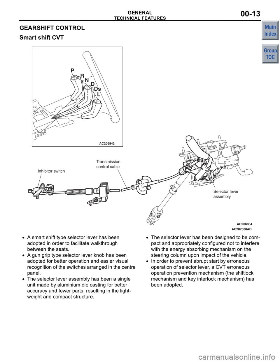
GEARSHIFT CONTROL
Smart shift CVT
AC206842
AC206864
AC207638
AB
P R
ND
Ds
L
Inhibitor switch Transmission
control cable
Selector lever
assembly
•A smart shift type selector lever h as b een
ado pted in orde r to facilitate walkthrou gh
bet wee n the seats.
•A gun grip type selector lever kno b has been
ado pted fo r better operat ion and easier visual
re cog nitio n of th e swit ches ar ra ng ed in th e ce ntre
p anel.
•The selecto r lever assembly has been a single
unit ma de by alu minium die casting f or bette r
accura cy and fewer pa rts, resu lting in the light
-
weig ht and compact struct ure.
•The selecto r lever has been designed to be com-
pa ct a nd appro priate ly configured no t to interf ere
with the en ergy absor bing mechanism on the
steerin g column upon impact of th e vehicle.
•In order to prevent abru pt st art b y erro neous
ope ration of selector lever , a CVT errone ous
ope ration preventio n mechanism (the shiftlock
m echa nis m and key interloc k mech anis m) h as
bee n adop ted.
Page 199 of 364
TECHNICAL FEATURES
GENERAL00-14
SUSPENSION
M2000023000460
AC405092AB
Lower arm
Front axle No.1
crossmember Stabilizer bar
Coil spring
Strut assembly
Front axle No.1
crossmember
Lower arm Strut assembly
Coil spring
Stabilizer bar
Shock absorber Coil spring
Torsion beam
and arm assembly
<4A9> <4G1>
•The
MacPherso n Strut suspe nsio n with comp ati-
ble characteristics of high rig idity and lig ht weight
has bee n adopted for the fron t suspension to
realise suf ficien t driving comfort.
•H-shaped to rsion bea m type suspe nsion has
bee n int roduced for t he rear suspension. This
suspe nsion has larg e suspen sion stro ke and pro
-
vides suf ficient driving comfort. With it s comp act
design , spe cio us interior sp ace has been
reserved.
Page 200 of 364

TECHNICAL FEATURES
GENERAL00-15
BRAKE
M2000024000270
SERVICE BRAKE
Brake system with high reliability and durability have
achieved distinguished braking performance.
AC601327AB
Brake booster (with variable
boosting mechanism)
Master cylinder Front disc brake
Hydraulic unit
(Integrated with ABS-ECU)
Rear drum brake
Brake booster (with variable
boosting mechanism)
Master cylinder
Front disc brake
Hydraulic unit
(Integrated with ABS-ECU) Rear disc brake
BRAKING PERFORMANCE
•Brake booster with 9-inch variab le amplificatio n
ratio me chanism by which greate r braking f orce
ca n be o bta ined with a less ped al pressure has
bee n inst alled (with b rake assist function).
•14-inch disc bra ke is inst alled on the front
wheels.
•15-inch disc bra ke is inst alled on the front
wheels.
•8-inch leading trailing type drum brake is installed
on the rear wheels.
•14-inch disc bra ke is inst alled on the rear
wheels.
ST ABILITY
•4-wheel anti-skid brak ing system (4ABS) is
ado pted to pre vent slippin g cause d by the vehicle
wheels locking up, in order t o maint ain a ppropri
-
ate bra kin g dist an ce, an d also t o ma inta in ve hicle
st ab ility an d steering function.
•Electronic br ake-force distribution (EBD) is
ad opted to m ain ta in th e max imu m am ount of rea r
braking force even whe n the vehicle's loa d is var
-
ie d.
•Diag onal split (X-type) brake fluid line is adopte d.
•V entilate d discs have bee n adopted to front
brakes to improve anti-fading per formance.
•A brake pe dal retraction suppression structu re
tha t restr ains the re traction of the brake pe dal
and reduces the shock to th e feet of the d rive r in
the even t of a frontal collision ha s been ado pted.
SERVICEABILITY
•Diagnosis function is adopted for the ABS system
in order t o make inspe ctio n easier .
•For the fron t disc bra kes, brake disc separate d
fron t hub is a dapted to make removal a nd instal
-
la tion easier .
•ABS-ECU and hydraulic unit have been inte-
grated to make them mor e comp act and lighte r.
Page 204 of 364
TECHNICAL FEATURES
GENERAL00-19
ACTIVE SAFETY
M2000031000528
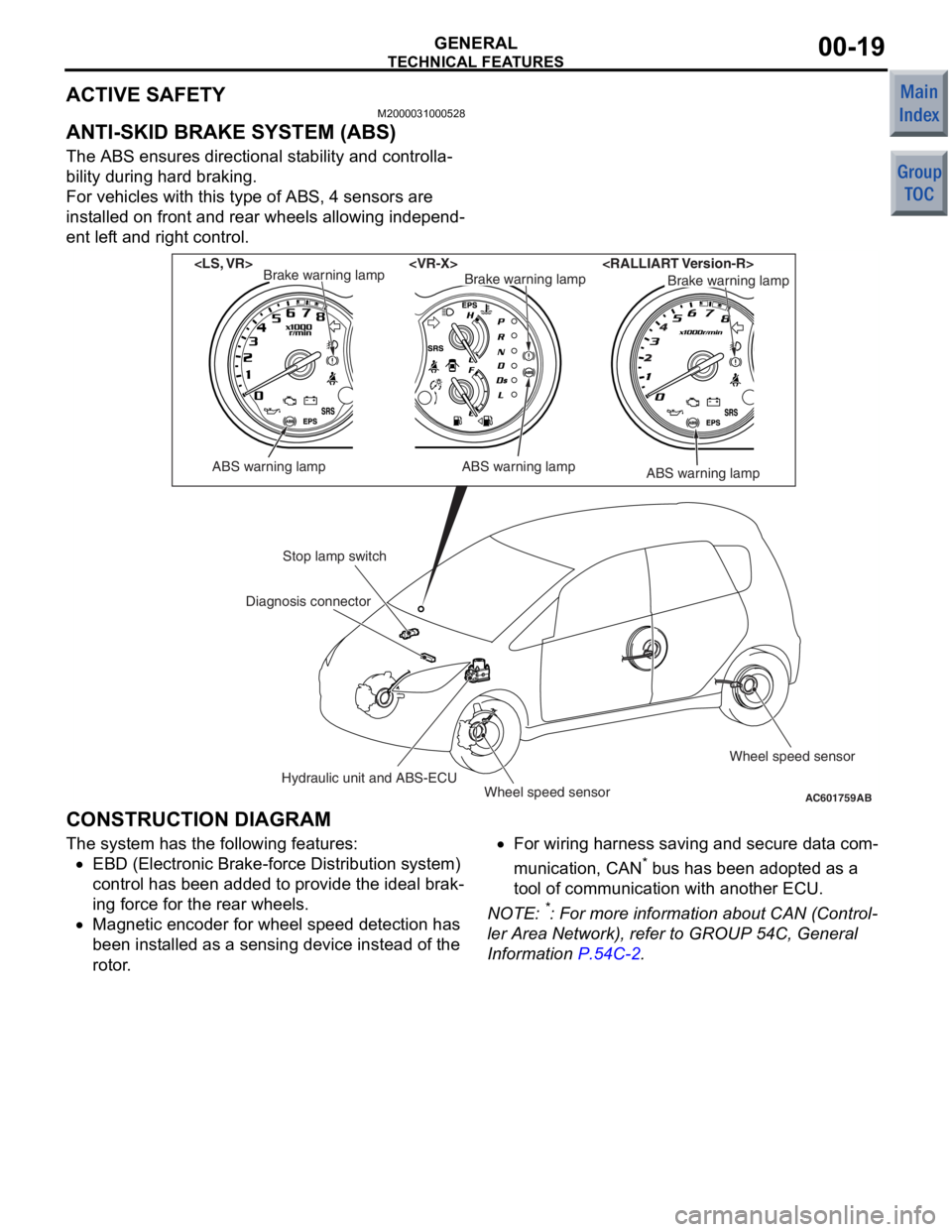
ANTI-SKID BRAKE SYSTEM (ABS)
The ABS ensures directional stability and controlla-
bility during hard braking.
For vehicles with this type of ABS, 4 sensors are
installed on front and rear wheels allowing independ
-
ent left and right control.
AC601759AB
ABS warning lamp
Brake warning lamp
ABS warning lamp
Brake warning lampBrake warning lamp
ABS warning lamp
Stop lamp switch
Hydraulic unit and ABS-ECUWheel speed sensor Wheel speed sensor
Diagnosis connector
CONSTRUCTION DIAGRAM
The syst
em has the following features:
•EBD (Electronic Bra ke-fo rce Distributio n system)
co ntrol has been added to provide t he ideal brak
-
in g force for th e rear wheels.
•Magnetic en coder for whee l speed de tection ha s
bee n inst alled as a se nsing device instead of the
rotor .
•For wiring h arness saving an d secure data com-
municatio n, CAN* b us h as be en ad opted a s a
too l of communication with another ECU.
NO TE: *: Fo r more information abo ut CAN (Control-
ler Area Netwo rk), re fer to GROUP 54C, Genera l
Information
P.54C-2.
Page 205 of 364
TECHNICAL FEATURES
GENERAL00-20
ELECTRONIC BRAKE FORCE DISTRIBU-
TION SYSTEM (EBD) CONTROL
In ABS, electronic control is used so the rear wheel
brake hydraulic pressure during braking is regulated
by rear wheel control solenoid valves in accordance
with the vehicle's rate of deceleration, and the front
and rear wheel slippage which are calculated from
the signals received from the various wheel speed
sensors. EBD control provides a high level of control
for both vehicle braking force and vehicle stability.
Page 206 of 364
TECHNICAL FEATURES
GENERAL00-21
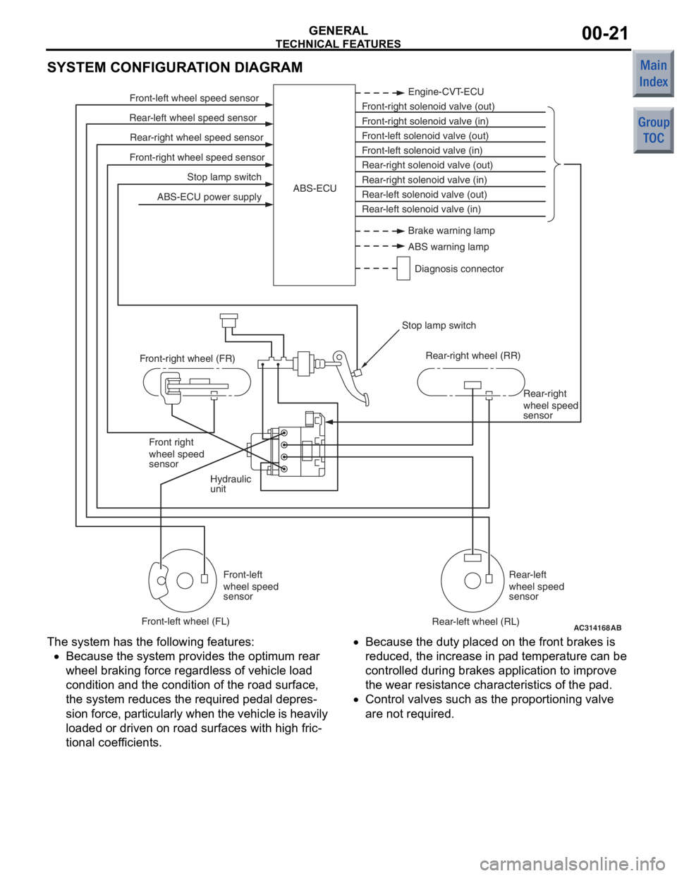
SYSTEM CONFIGURATION DIAGRAM
AC314168
Stop lamp switch
Front-right wheel speed sensor Rear-right wheel speed sensor
Rear-left wheel speed sensor Front-left wheel speed sensor
ABS-ECU power supply Engine-CVT-ECU
Front-right solenoid valve (out)
Front-right solenoid valve (in)
Front-left solenoid valve (out)
Front-left solenoid valve (in)
Rear-right solenoid valve (out)
Rear-right solenoid valve (in)
Rear-left solenoid valve (out)
Rear-left solenoid valve (in)
ABS-ECU
Hydraulic
unit Rear-right
wheel speed
sensor
Front right
wheel speed
sensor
Front-left
wheel speed
sensor Rear-left
wheel speed
sensor
Front-right wheel (FR)
Front-left wheel (FL) Rear-right wheel (RR)
Rear-left wheel (RL)
Stop lamp switch
AB
Brake warning lamp
ABS warning lamp
Diagnosis connector
The syst em has the following features:
•Because the system p rovides t he optimum rea r
wheel braking force regardless of vehicle load
co ndition a nd the condition of the road surface,
the system reduces the required pedal depre s
-
sion fo rce, particularly wh en th e veh icle is h eavily
lo aded o r driven on road surfaces with high fric
-
tional coef ficients.
•Because the duty place d on th e front brakes is
redu ced, th e increase in p ad tempe rature can be
controlled d uring brake s ap plication to impro ve
the we ar resist ance characteristics of the pad.
•Contro l valves such as the propo rtioning valve
are not required.
Page 207 of 364
TECHNICAL FEATURES
GENERAL00-22
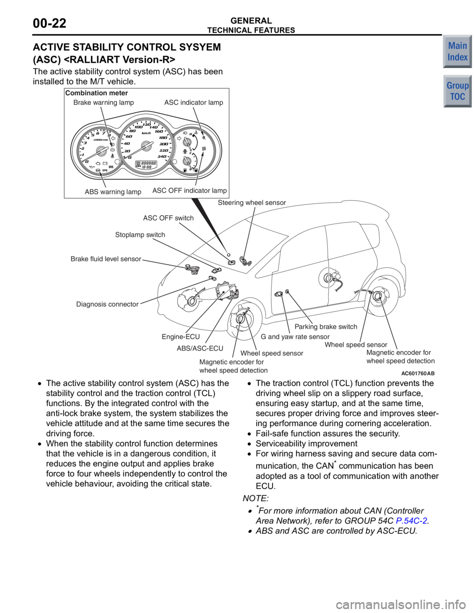
ACTIVE STABILITY CONTROL SYSYEM
(ASC)
The active stability control system (ASC) has been
installed to the M/T vehicle.
AC601760AB
ABS warning lamp
Diagnosis connector Stoplamp switch
Steering wheel sensor
Wheel speed sensor Wheel speed sensor
G and yaw rate sensorParking brake switch
ASC OFF switch ASC indicator lamp
ASC OFF indicator lamp
Brake warning lamp
Combination meter
Brake fluid level sensor ABS/ASC-ECU
Engine-ECU
Magnetic encoder for
wheel speed detection Magnetic encoder for
wheel speed detection
•The
active st ability control syst em (ASC) has the
st ab ility control and t he traction control (TCL)
fun ctio ns. By the integra ted control with th e
ant i-lock b rake system, the system stabilizes th e
ve hicle attitu de and at the same time secures the
drivin g force.
•When the st ability control fun ction dete rmin es
tha t the vehicle is in a dangerou s condition, it
redu ces the e ngine outpu t and a pplies b rake
force to f our wheels indepe ndently to control th e
ve hicle be haviour, avoiding the critical state.
•The tract ion control (TCL) fun ction prevent s the
drivin g wheel slip on a slippery road sur face,
ensurin g easy st artup, an d at the same time,
secure s proper drivin g force and improves ste er
-
in g perfo rmance du ring cornering acce leration.
•Fail-safe functio n assures the security.
•Serviceability imp rovement
•For wiring h arness saving an d secure data com-
municatio n, the CAN* co mmunicatio n has been
ado pted a s a t ool o f commun ication with ano ther
ECU.
NO TE: .
•*For more informatio n about CAN (Con troller
Area Net wor k), refe r to GROUP 54C
P.54C-2.
•ABS and ASC are controlled by ASC-ECU.
Page 208 of 364
TECHNICAL FEATURES
GENERAL00-23
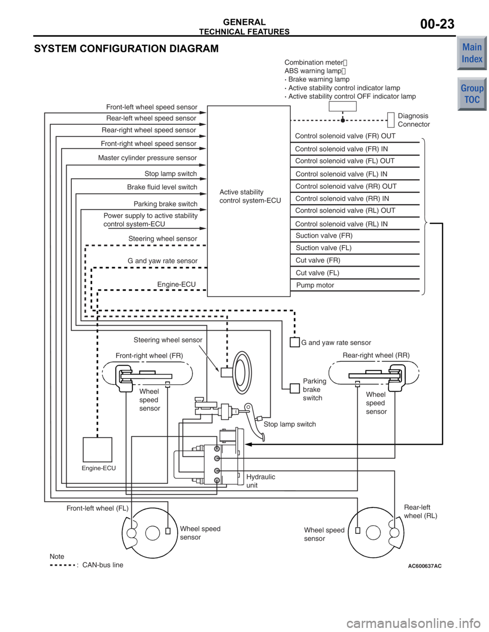
SYSTEM CONFIGURATION DIAGRAM
AC600637AC
Combination meter�
ABS warning lamp �
· Brake warning lamp
· Active stability control indicator lamp
· Active stability control OFF indicator lamp
Diagnosis
Connector
Control solenoid valve (FR) OUT
Control solenoid valve (FR) IN
Control solenoid valve (FL) OUT
Control solenoid valve (FL) IN
Control solenoid valve (RR) OUT
Control solenoid valve (RR) IN
Control solenoid valve (RL) OUT
Control solenoid valve (RL) IN Suction valve (FR)
Suction valve (FL)
Cut valve (FR)
Cut valve (FL) Pump motor
Active stability
control system-ECU
Front-left wheel speed sensor
Rear-left wheel speed sensor
Front-right wheel speed sensor Rear-right wheel speed sensor
Master cylinder pressure sensor Stop lamp switch
Parking brake switch
Brake fluid level switch
Power supply to active stability
control system-ECU Steering wheel sensor
G and yaw rate sensor
Engine-ECU
Steering wheel sensor
Front-right wheel (FR)
Wheel
speed
sensor
Engine-ECU
G and yaw rate sensor
Parking
brake
switch Rear-right wheel (RR)
Wheel
speed
sensor
Stop lamp switch
Hydraulic
unit Wheel speed
sensor Rear-left
wheel (RL)
Wheel speed
sensor
Front-left wheel (FL)
Note
: CAN-bus line