2006 MITSUBISHI COLT low oil pressure
[x] Cancel search: low oil pressurePage 64 of 364

BASE ENGINE
ENGINE MECHANICAL <4A9>11A-16
CAMSHAFT
AK304999
Intake camshaft
Exhaust camshaft
AB
Hollow section
Advance
oil channel
Retard
oil channel
Cam positon sensing ring
Dowel pinSealing cap
The lightweight camshaf t is ach i eved by the h o llo w
design.
Oil channels run through the int a ke camshaf t,
through
wh ich oil is sent from t he oil fee der co ntrol
valve to
the V . V . T . sprocket.
A cam position sen s in g ring is press-fitt ed onto the
rear port
i on o f the int a ke camshaf t.
ItemDimension
Overall length
mmIntake407.5
Exhaust361.9
Journal mm26
Valve lift mmIntake8.4
Exhaust7.9
OIL FEEDER CONT ROL V A L V E(OCV)
AK302997AB
Spring guideValve sleeve
Plunger spring Spool
O-ring
Insulation coilar
StatorGuide cap Bracket
Yo k eSeal cap
Plunger
Shaft Terminal
Bobbin
Tape
Enameled copper wire
Drain
Drain
Pump
Pressure
chamber
Default
pressure
chamber
The oil fee
der co ntrol valve is essen t ially a solenoid
valve, re
gulat ed by the en gine -ECU or
engin
e -A-M/T -ECU signals to feed o il to the V . V . T .
sprocket
assemb ly t o move the van e rotor .
Page 80 of 364

BASE ENGINE
ENGINE MECHANICAL <4A9>11A-32
CAMSHAFT
AK304999
Intake camshaft
Exhaust camshaft
AB
Hollow section
Advance
oil channel
Retard
oil channel
Cam positon sensing ring
Dowel pinSealing cap
The lightweight camshaf t is ach i eved by the h o llo w
design.
Oil channels run through the int a ke camshaf t,
through
wh ich oil is sent from t he oil fee der co ntrol
valve to
the V . V . T . sprocket.
A cam position sen s in g ring is press-fitt ed onto the
rear port
i on o f the int a ke camshaf t.
ItemDimension
Overall length
mmIntake407.5
Exhaust361.9
Journal mm26
Valve lift mmIntake8.4
Exhaust7.9
OIL FEEDER CONT ROL V A L V E(OCV)
AK302997AB
Spring guideValve sleeve
Plunger spring Spool
O-ring
Insulation coilar
StatorGuide cap Bracket
Yo k eSeal cap
Plunger
Shaft Terminal
Bobbin
Tape
Enameled copper wire
Drain
Drain
Pump
Pressure
chamber
Default
pressure
chamber
The oil fee
der co ntrol valve is essen t ially a solenoid
valve, re
gulat ed by the en gine -ECU or
engin
e -A-M/T -ECU signals to feed o il to the V . V . T .
sprocket
assemb ly t o move the van e rotor .
Page 89 of 364

GENERAL INFORMATION
ENGINE LUBRICATION12-2
GENERAL INFORMATION
M2120000100175
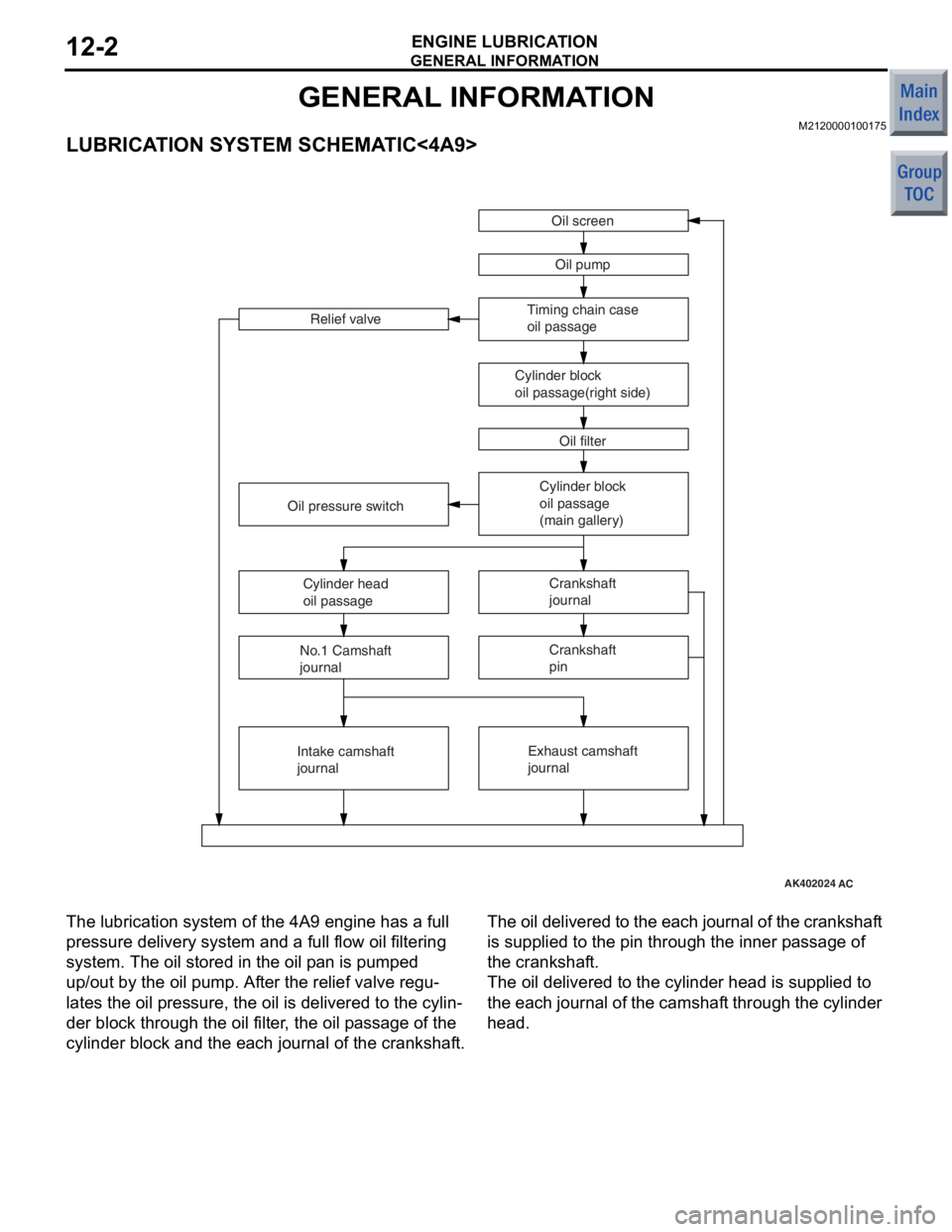
LUBRICATION SYSTEM SCHEMATIC<4A9>
AK402024AC
Oil screenOil pump
Timing chain case
oil passage
Cylinder block
oil passage(right side) Oil filter
Relief valve
Cylinder block
oil passage
(main gallery)Crankshaft
journal
Exhaust camshaft
journal
Oil pressure switch
Cylinder head
oil passage
No.1 Camshaft
journal
Intake camshaft
journal Crankshaft
pin
The lu
brication system of th e 4A9 en gine has a full
pressure de
livery system and a full flow oil filtering
system. The o
il stored in the oil p an is pumped
up/out
by th e oil pump. Af ter the relie f valve regu
-
lates the oil p r essure, th e oil is delivere d to th e cylin-
der block through the o il f ilte r , the o il p a ssag e of the
cylinde
r blo ck a nd the each jou r nal o f the crankshaf t.
The oil del ivered to the ea ch jo urnal of th e cranksh af t
is supplied
to the pin th rough the in ner p a ssage of
the crankshaf
t.
The oil delivered to the cylinder head is supplied t o
the ea
ch journa l of the camshaf t th rough the cylinde r
head.
Page 91 of 364

OIL PUMP<4A9>
ENGINE LUBRICATION12-4
OIL PUMP<4A9>
M2120002000044
AK305367AB
Timing chain caseOil pump
inner rotor
Oil pump
outer rotor Oil seal
Cover
Machine screw
A
A-A
A
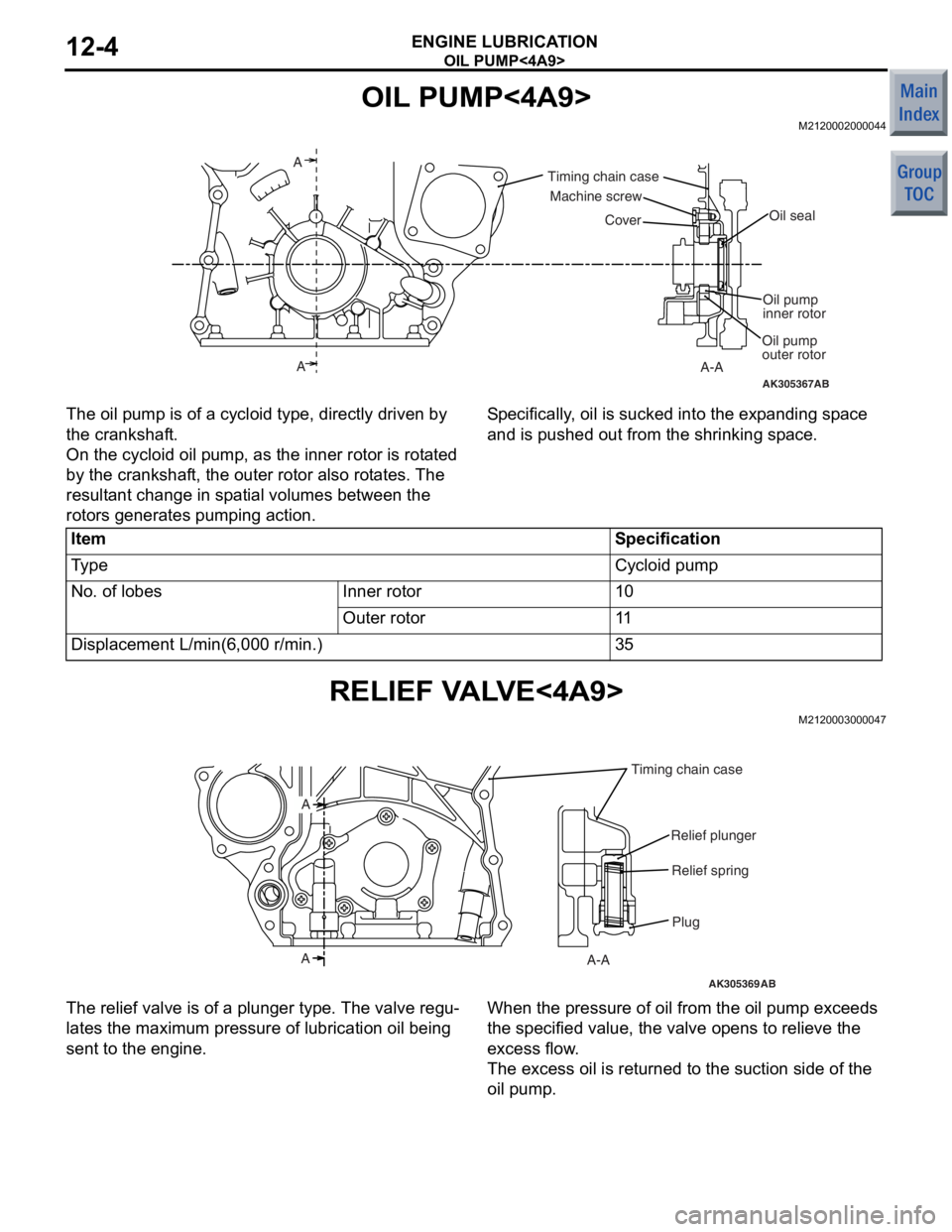
The oil pump is of a
cyclo i d type, d i rectly driven by
the crankshaf
t.
On the cycloid o il p u mp, as th e inn e r rotor is ro t a ted
by th
e cran kshaf t, the o u ter rot o r also rot a tes. The
result
a n t ch ange in sp at ial volu mes betwee n the
rotors
genera t es p u mping action .
Sp e c ifically , o il is sucked into the exp and ing sp ace
and is pushed
out from the shrinking sp ace.
ItemSpecification
Ty p eCycloid pump
No. of lobesInner rotor10
Outer rotor11
Displacement L/min(6,000 r/min.)35
RELIEF V A L V E<4A9>
M21200030 0004 7
AK305369AB
Plug
A-A
A A
Relief spring
Relief plunger
Timing chain case
The relief valve is of a
plun ger type. The valve re gu-
lates the maximum pre ssu re of lubricatio n oil being
sent
to the e ngin e .
When the pressure of oil from the oil p u mp exceeds
the specified
value, the valve o pens to relieve the
excess flow
.
The excess o il is ret u rned t o the suct ion side of the
oil pump
.
Page 105 of 364

IGNITION TIMING AND DISTRIBUTION CONTROL
MULTIPOINT FUEL INJECTION (MPI) <4A9>13A-11
IGNITION TIMING AND DISTRIBUTION CONTROL
M2132005000750
This control system is basically the same as that of
the 4G1-Non-Turbo engine used in the COLT.
System Configuration Diagram
AK402031
Ignition switch-IG
Ignition
coil Battery
Spark plug
Cylinder No. 1 2 3 4
Manifold absolute
pressure sensor
Intake air temperature sensor
Barometric pressure sensor
Engine coolant
temperature sensor
Camshaft position sensor
Crank angle sensor
Detonation sensor
Ignition switch-ST
Engine-ECU
CVT-ECU
AG
OTHER CONTROL FUNCTI O NS
M21320100 0059 6
The following co ntrols are b a sically t he sa me a s
those
of the 4G1 - No n
−turbo eng ine u s ed in the
CO
L
T
.
•ENGINE CONTROL RELA Y CONTROL
•THROTTLE VA L V E C O NTROL SER VO R E LA Y
CONTROL
•MIVEC (Mitsub i sh i Inno vative V a lve T i ming Elec-
tronic Con t rol System)
•FUEL PUMP RELA Y CONTROL
•OXYGEN S E NSOR HEA T E R CONTR O L
•A/C RELAY CONTROL
•ALTER N A T OR CONTROL
Page 110 of 364

DIAGNOSIS SYSTEM
MULTIPOINT FUEL INJECTION (MPI) <4A9>13A-16
P0606Microcomputer malfunctionAbnormality in engine-ECU
or engine-CVT-ECU
P0622Alternator FR terminal systemOpen circuit or short-circuit in
system-related circuits−
P0638*Throttle valve control servo circuit
range/performance problemAbnormal throttle valve control
servoON
P0642*Throttle position sensor power
supplyAbnormality in engine-ECU
or engine-CVT-ECU
P0657*Throttle valve control servo relay
circuit malfunctionOpen circuit or short-circuit in
sensor-related circuitsON
P1021Oil feeder control valve systemOpen circuit or short-circuit in
solenoid valve-related circuitsON
P1602*Communication malfunction
(between engine-ECU
engine-CVT-ECU
processor and system LSI)Abnormality in engine-ECU
or engine-CVT-ECU
P1603*Battery backup circuit malfunctionOpen circuit or short-circuit in
system-related circuitsON
P2100*Throttle valve control servo circuit
(open)Open circuit in throttle valve control
servo-related circuitON
P2101*Throttle valve control servo
magneto malfunctionShort-circuit in system-related
circuitsON
P2108*Throttle valve control servo
processor malfunctionAbnormality in engine-ECU
or engine-CVT-ECU
P2122*Accelerator pedal position sensor
(main) circuit low inputOpen circuit or short-circuit in
sensor-related circuitsON
P2123*Accelerator pedal position sensor
(main) circuit high inputOpen circuit in sensor-related
circuitsON
P2127*Accelerator pedal position sensor
(sub) circuit low inputOpen circuit or short-circuit in
sensor-related circuitsON
P2128*Accelerator pedal position sensor
(sub) circuit high inputOpen circuit in sensor-related
circuitsON
P2135*Throttle position sensor (main and
sub) range/performance problemAbnormal sensor outputON
P2138*Accelerator pedal position sensor
(main and sub) range/performance
problemAbnormal sensor outputON
P2226Barometric pressure sensor
systemAbnormality in engine-ECU
or engine-CVT-ECU
U1073Bus offAbnormality in CAN bus line−
U1102ABS-ECU time-outAbnormality in CAN bus line−
U1106EPS-ECU time-outAbnormality in CAN bus line−
U1108Combination meter time-outAbnormality in CAN bus lineON
U 111 0A/C-ECU time-outAbnormality in CAN bus line−
Code No. Diagnosis item Main diagnosis contents Engine
warning lamp
Page 117 of 364
![MITSUBISHI COLT 2006 Service Repair Manual
GENERAL INFORMATION
MULTIPOINT FUEL INJECTION (MPI) <4G1>13B-3
SYSTEM BLOCK DIAGRAM
AK600528
Barometric pressure sensorEngine control unitEngine-ECU
[1] Fuel injection control
[2] Throttle valve open MITSUBISHI COLT 2006 Service Repair Manual
GENERAL INFORMATION
MULTIPOINT FUEL INJECTION (MPI) <4G1>13B-3
SYSTEM BLOCK DIAGRAM
AK600528
Barometric pressure sensorEngine control unitEngine-ECU
[1] Fuel injection control
[2] Throttle valve open](/manual-img/19/57093/w960_57093-116.png)
GENERAL INFORMATION
MULTIPOINT FUEL INJECTION (MPI) <4G1>13B-3
SYSTEM BLOCK DIAGRAM
AK600528
Barometric pressure sensorEngine control unitEngine-ECU
[1] Fuel injection control
[2] Throttle valve opening control
and idle speed control
[3] MIVEC (Mitsubishi Innovative
Valve timing Electronic
control system)
[4] Ignition timing control
[5] Engine control relay control
[6] Throttle valve control servo
relay control
[7] Fuel pump relay control
[8] Oxygen sensor (front) heater
control
[9] Oxygen sensor (rear) heater
control
[10] Fuel pressure control
[11] Waste gate control
[12] Fan relay control
[13] A/C compressor relay
control
[14] Alternator control
[15] Purge control
[16] Diagnostic output
[17] RAM data transmission Throttle valve control unit
Throttle opening feedback control
Engine coolant
temperature sensor Intake air temperature sensor Air flow sensor
Accelerator pedal
position sensor (main) Throttle position sensor (sub)
Camshaft position sensor
Crank angle sensor
Oxygen sensor (front)
Oxygen sensor (rear)
Alternator FR terminal
Clutch switch
Detonation sensor
Ignition switch-IG
Ignition switch-ST
Stop lamp switch
Power supply
Throttle position sensor (main)
Accelerator pedel
position sensor (sub)
Throttle valve control servo No.1 injector
No.2 injector
No.3 injector
No.4 injector
No.1 Ignition coil
No.2 Ignition coil
No.3 Ignition coil
No.4 Ignition coil
Engine control relay
Throttle valve control servo relay
Waste gate solenoid valve
A/C compressor relay
Fuel pump relay
Alternator G terminal
Cooling fan control relay (Hi, Lo)
Purge control solenoid valve
Diagnostic output terminal
Oxygen sensor (front) heater
Oxygen sensor (rear) heater Oil feeder control valve
(for MIVEC)
Fuel pressure control
solenoid valve
AB
Page 118 of 364

GENERAL INFORMATION
MULTIPOINT FUEL INJECTION (MPI) <4G1>13B-4
CONTROL SYSTEM DIAGRAM
AK600529AB
6 Oil feeder control valve
1 Oxygen sensor
(front)
8 Engine coolant
temperature sensor
3
Throttle valve control servo
10
Throttle position sensor (main)
5 Throttle position sensor (sub)
2 Purge control
solenoid valve
4 Fuel pressure
solenoid valve
7 Crank angle sensor
9
Detonation sensor
4
Intake air
temperature
sensor
3
Air flow sensor
Waste gate
actuator Canister
Check
valve Air by-pass valve
Fuel pressure regulatorFrom
fuel pump
To fuel
tank
Catalytic converter
Catalytic
converter
Air
inlet
Oxygen sensor (front)
Oxygen sensor (rear)
Air flow sensor
Intake air temperature
sensor
Throttle position
sensor
(sub)
Camshaft position
sensor
Crank angle sensor
Engine coolant
temperature sensor
Detonation sensor
Throttle position
sensor (main) Power supply
Ignition switch-IG
Ignition switch-ST
Accelerator pedal
position sensor
(main)
Accelerator pedal
position sensor
(sub)
Alternator FR
terminal
Stop lamp switch
Clutch switchEngine-
ECUEngine control relay
Fuel pump relay
A/C compressor relay
Throttle valve
control servo relay
Ignition coil
Cooling fan
control relay
(Hi, Lo)
Diagnosis output
Alternator G terminal
Oxygen sensor (front)
heater
Oxygen sensor (rear)
heater
Barometric
pressure
sensor
1 Injector
5 Waste gate
solenoid valve
2 Oxygen sensor
(rear)
6 Camshaft position sensor
1
2
3
4
5
6
7
8
9
10 Injector
Purge control
solenoid valve
Throttle valve
control servo
Fuel pressure
solenoid valve
Waste gate
solenoid valve
Oil feeder control
valve
1
2
3
4
5
6