2006 MITSUBISHI COLT steering wheel
[x] Cancel search: steering wheelPage 86 of 364

GENERAL INFORMATION
REAR SUSPENSION34-2
GENERAL INFORMATION
M2340000100825
Newly developed H-shaped torsion beam type sus-
pension has been introduced.
•The coil spring is installed under the rear floor,
the torsion beam and arm assembly is installed in
front of the spare tyre house, and the shock
absorber is installed outside, so that the large
cabin space is achieved.
•The arm bushing with the toe control function is
adopted to optimise the tyre steering angle using
the bushing deflection caused by lateral force
and longitudinal force generated at cornering, so
that the good cornering performance is secured.
•The layout of shock absorber is optimised for
smooth riding.
•Long wheel stroke secures sufficient road holding
quality.
•The hub-integrated unit bearing is adopted for the
wheel bearing for sufficient suspension rigidity
(Refer to GROUP 27, Rear Axle
P.27-2).
•The dumping characteristic of shock absorber
has been changed. <4G1>
•The urethane bump stopper has been adopted to
improve the linearity. <4G1>
•Torsion beam rigidity has been improved <4G1>
CONSTRUCTION DIAGRAM
AC405533AD
Coil spring
Shock absorber
Torsion beam and arm assembly
Arm bushing
Torsion bar
Section A – A
<4G9>
A
A Torsion beam and arm assembly
Section A – A
<4G1>
Torsion beam and arm assembly
Page 107 of 364

CONTROLLER AREA NETWORK (CAN)
MULTIPOINT FUEL INJECTION (MPI) <4A9>13A-13
CONTROLLER AREA NETWORK (CAN)
M2132019000292
Establishing communication without fail is designed
by CAN communication protocol. Refer to Group
54C-CAN
P.54C-2 for the details about CAN.
The signals input into engine-ECU
engine-CVT-ECU
CAN Communication Input Signal Table
Input signal nameTransmitter ECU
Motor electric current signalEPS-ECU
Compressor signalMeter and A/C-ECU
Idle-up request signal
Cooling fan request signal
SYSTEM CONFIGURATION DIAGRAM
AK600527AB
Engine-ECU
Engine-CVT
-ECU
M.U.T.-III
EPS-ECU ETACS
-ECU
Steering
wheel
sensor G and
yaw rate
sensor
ABS-ECU
CAN_H
CAN_L Diagnosis
connector Combination
meter
(incorporating
meter-A/C-ECU)
: Shows sub bus line. : Shows main bus line. Terminal resistor
Terminal resistor
Main bus lines
Page 127 of 364

CONTROLLER AREA NETWORK (CAN)
MULTIPOINT FUEL INJECTION (MPI) <4G1>13B-13
CONTROLLER AREA NETWORK (CAN)
M2132019000300
Establishing communication without fail is designed
by CAN communication protocol. Refer to Group
54C-CAN
P.54C-2 for the details about CAN.
The signals input into engine-ECU are as follows:
CAN Communication Input Signal Table
Input signal nameTransmitter ECU
Motor electric current signalEPS-ECU
Compressor signalMeter and A/C-ECU
Idle-up request signal
Cooling fan request signal
SYSTEM CONFIGURATION DIAGRAM
AK600527AC
Engine-
ECU
M.U.T.-III
EPS-ECU ETACS
-ECU
Steering
wheel
sensor G and
yaw rate
sensor
ASC-ECU
CAN_H
CAN_L Diagnosis
connector Combination
meter
(incorporating
meter-A/C-ECU)
: Shows sub bus line. : Shows main bus line. Terminal resistor
Terminal resistor
Main bus lines
Page 140 of 364

STRUCTURE
CONTROLLER AREA NETWORK (CAN)54C-3
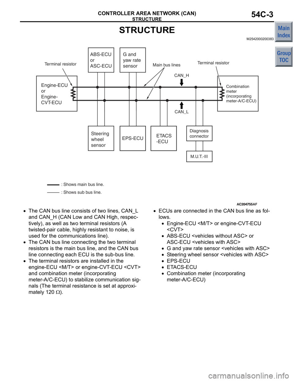
STRUCTURE
M2542000200383
AC204755AC204755AF
Engine-ECU
or
Engine-
CVT-ECUEPS-ECU
M.U.T.-III
ETACS
-ECU
ABS-ECU
or
ASC-ECU
Steering
wheel
sensor G and
yaw rate
sensor
CAN_H
CAN_L Diagnosis
connector
Combination
meter
(incorporating
meter-A/C-ECU)
: Shows sub bus line. : Shows main bus line. Terminal resistor
Terminal resistor Main bus lines
•The CAN bu s line consist s of two lines, CAN_L
and
CAN_H (CAN Low and CAN Hig h , respec
-
tively), as well as two terminal re sistors (A
twisted-p
a ir cable, highly resist ant to noise, is
used for
the communicatio n s line) .
•The CAN bu s line connectin g the two terminal
resist
ors is th e main bus line, an d the CAN bus
line connecting
each ECU is th e su b-bus lin e.
•The terminal resistors are inst alled in the
eng
ine-ECU
and
combin ation mete r (incorpora t ing
meter-A/C-ECU) to st
abi lize co mmunicatio n sig
-
nals (The terminal resist ance is se t at ap proxi-
mately 120 Ω).
•ECUs are conn ected in th e CAN bus line as fo l-
lows.
•En gine -ECU
•ABS-ECU
A
S C-ECU
•G and ya w ra te se nsor
•St e e ring wh eel sensor
•EPS-ECU
•E T ACS-ECU
•Co mbinatio n me ter (in c orpo rating
meter-A/C-ECU)
Page 188 of 364

PRODUCT FEATURES
GENERAL00-3
PRODUCT FEATURES
M2000005000475
•COLT has been equipped with the new 1,500 mL
aluminium die-cast engine (4A9-engine) for fur
-
ther refinements of comfort driving, excellent
power performance, fuel economy, and ecology
performance.
•The body and suspension of COLT RALLIART
Version-R have been thoroughly tuned to
increase the 4G1-engine output which enables
dynamic driving.
•The robust image suited for the dynamic driving
has been adopted for the appearance.
SPORTY AND STYLISH DESIGN
•Bucket-like front seats
•Sport seats exclusive to the models with turbo-
charger
•15-inch aluminium wheel
•High-contrast combination meter
•Robust appearance by new shaped front bumper
adaptation and rear bumper change
•Black overfender
•16-inch aluminium wheel
ACTIVE DRIVING AND HIGH QUALITY
•For 4A9-engine, the aluminium die-cast cylinder
block has been installed for weight reduction of
the vehicle.
•For 4G1-engine, turbo-charger model has been
introduced to increase output and torque,
enhancing sporty image.
•Sporty driving has been ensured by the
"GETRAG" 5-speed manual transmission (floor
shift).
•The suspension has been tuned to improve cor-
nering and stability at high speed.
•A strut tower bar has been adopted to improve
the body rigidity.
•Electric power steering system has been
improved and EPS-ECU has been additionally
equipped with the return control logic, resulting in
superior steering wheel return control and better
steering feel equal to or better than that for other
models with hydraulic power steering.
Page 200 of 364

TECHNICAL FEATURES
GENERAL00-15
BRAKE
M2000024000270
SERVICE BRAKE
Brake system with high reliability and durability have
achieved distinguished braking performance.
AC601327AB
Brake booster (with variable
boosting mechanism)
Master cylinder Front disc brake
Hydraulic unit
(Integrated with ABS-ECU)
Rear drum brake
Brake booster (with variable
boosting mechanism)
Master cylinder
Front disc brake
Hydraulic unit
(Integrated with ABS-ECU) Rear disc brake
BRAKING PERFORMANCE
•Brake booster with 9-inch variab le amplificatio n
ratio me chanism by which greate r braking f orce
ca n be o bta ined with a less ped al pressure has
bee n inst alled (with b rake assist function).
•14-inch disc bra ke is inst alled on the front
wheels.
•15-inch disc bra ke is inst alled on the front
wheels.
•8-inch leading trailing type drum brake is installed
on the rear wheels.
•14-inch disc bra ke is inst alled on the rear
wheels.
ST ABILITY
•4-wheel anti-skid brak ing system (4ABS) is
ado pted to pre vent slippin g cause d by the vehicle
wheels locking up, in order t o maint ain a ppropri
-
ate bra kin g dist an ce, an d also t o ma inta in ve hicle
st ab ility an d steering function.
•Electronic br ake-force distribution (EBD) is
ad opted to m ain ta in th e max imu m am ount of rea r
braking force even whe n the vehicle's loa d is var
-
ie d.
•Diag onal split (X-type) brake fluid line is adopte d.
•V entilate d discs have bee n adopted to front
brakes to improve anti-fading per formance.
•A brake pe dal retraction suppression structu re
tha t restr ains the re traction of the brake pe dal
and reduces the shock to th e feet of the d rive r in
the even t of a frontal collision ha s been ado pted.
SERVICEABILITY
•Diagnosis function is adopted for the ABS system
in order t o make inspe ctio n easier .
•For the fron t disc bra kes, brake disc separate d
fron t hub is a dapted to make removal a nd instal
-
la tion easier .
•ABS-ECU and hydraulic unit have been inte-
grated to make them mor e comp act and lighte r.
Page 203 of 364

TECHNICAL FEATURES
GENERAL00-18
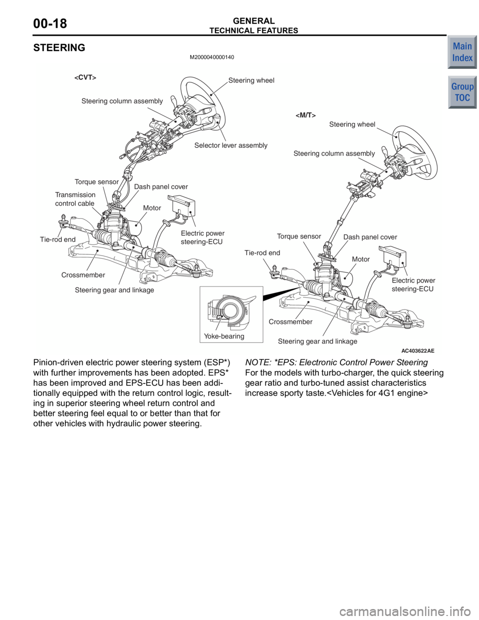
STEERING
M2000040000140
AC403622
Steering wheel
Steering wheel
Steering column assembly
Torque sensor
Tie-rod end
Yoke-bearing
Crossmember
Steering gear and linkage
Electric power
steering-ECU
Motor
AE
Motor
Electric power
steering-ECU
Steering gear and linkage
Crossmember
Tie-rod end
Torque sensor
Transmission
control cable
Steering column assembly
Selector lever assembly
Dash panel cover
Dash panel cover
Pinion -driven electric p owe r ste ering system (ESP*)
with further improvement s has been adopted. EPS*
has been improved and EPS-ECU has been addi
-
tionally equipped with the return contro l logic, resu lt-
ing in superior stee ring whe el ret urn co ntrol and
better steering fee l equ al to or bett er than that for
other vehicles with hydraulic power steering.
NO TE: *EPS: Electronic Control Power S teerin g
For the mode ls with turb o-charge r, t he qu ick ste ering
gear rat io an d turbo -tuned a ssist chara cteristics
increase sporty tast e.
Page 207 of 364

TECHNICAL FEATURES
GENERAL00-22
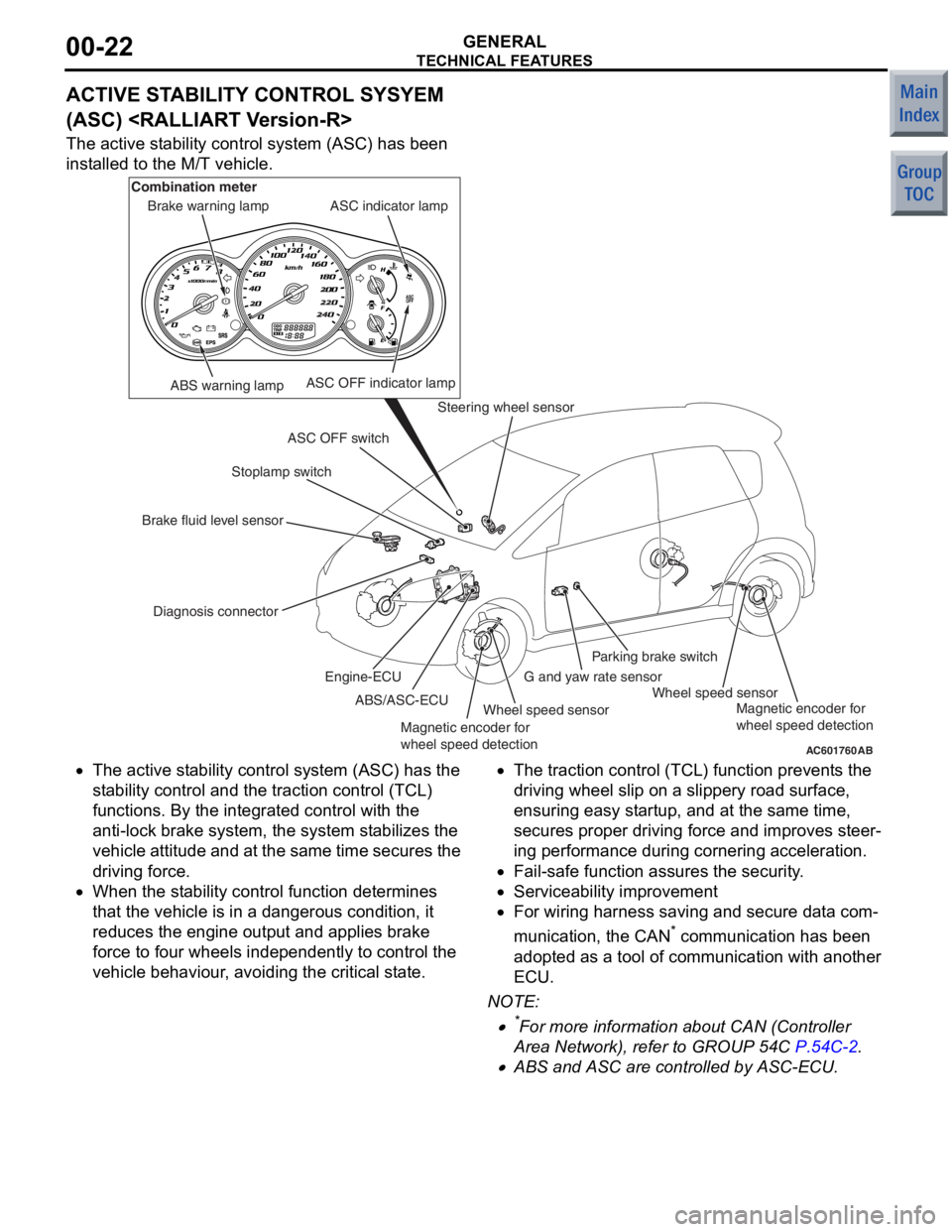
ACTIVE STABILITY CONTROL SYSYEM
(ASC)
The active stability control system (ASC) has been
installed to the M/T vehicle.
AC601760AB
ABS warning lamp
Diagnosis connector Stoplamp switch
Steering wheel sensor
Wheel speed sensor Wheel speed sensor
G and yaw rate sensorParking brake switch
ASC OFF switch ASC indicator lamp
ASC OFF indicator lamp
Brake warning lamp
Combination meter
Brake fluid level sensor ABS/ASC-ECU
Engine-ECU
Magnetic encoder for
wheel speed detection Magnetic encoder for
wheel speed detection
•The
active st ability control syst em (ASC) has the
st ab ility control and t he traction control (TCL)
fun ctio ns. By the integra ted control with th e
ant i-lock b rake system, the system stabilizes th e
ve hicle attitu de and at the same time secures the
drivin g force.
•When the st ability control fun ction dete rmin es
tha t the vehicle is in a dangerou s condition, it
redu ces the e ngine outpu t and a pplies b rake
force to f our wheels indepe ndently to control th e
ve hicle be haviour, avoiding the critical state.
•The tract ion control (TCL) fun ction prevent s the
drivin g wheel slip on a slippery road sur face,
ensurin g easy st artup, an d at the same time,
secure s proper drivin g force and improves ste er
-
in g perfo rmance du ring cornering acce leration.
•Fail-safe functio n assures the security.
•Serviceability imp rovement
•For wiring h arness saving an d secure data com-
municatio n, the CAN* co mmunicatio n has been
ado pted a s a t ool o f commun ication with ano ther
ECU.
NO TE: .
•*For more informatio n about CAN (Con troller
Area Net wor k), refe r to GROUP 54C
P.54C-2.
•ABS and ASC are controlled by ASC-ECU.