Page 2 of 364

GENERAL INFORMATION
ANTI-SKID BRAKE SYSTEM (ABS)35B-2
GENERAL INFORMATION
M2351000100409
FEATURES
The ABS ensures directional stability and controlla-
bility during hard braking.
For vehicles with this type of ABS, 4 sensors (4
channels) are installed on front and rear wheels
allowing independent left and right control.
The system has the following features:
•EBD (Electronic Brake-force Distribution system)
control has been added to provide the ideal brak
-
ing force for the rear wheels.
•Magnetic encoder for wheel speed detection has
been installed as a sensing device instead of the
rotor.
•For wiring harness saving and secure data com-
munication, CAN* bus has been adopted as a
tool of communication with another ECU.
NOTE: *: For more information about CAN (Control-
ler Area Network), refer to Group 54C, General Infor-
mation P.54C-2.
EBD CONTROL
In ABS, electronic control is used so the rear wheel
brake hydraulic pressure during braking is regulated
by rear wheel control solenoid valves in accordance
with the vehicle's rate of deceleration, and the front
and rear wheel slippage which are calculated from
the signals received from the various wheel speed
sensors. EBD control provides a high level of control
for both vehicle braking force and vehicle stability.
The system has the following features:
•Because the system provides the optimum rear
wheel braking force regardless of vehicle load
condition and the condition of the road surface,
the system reduces the required pedal depres
-
sion force, particularly when the vehicle is heavily
loaded or driven on road surfaces with high fric
-
tional coefficients.
•Because the duty placed on the front brakes is
reduced, the increase in pad temperature can be
controlled during brakes application to improve
the wear resistance characteristics of the pad.
•Control valves such as the proportioning valve
are not required.
SPECIFICATIONS
ItemSpecification
ABS control method4-sensor, 4-channel
Wheel speed
sensorMagnetic encoderFront86 (N pole:43 S pole:43)
Rear86 (N pole:43 S pole:43)
Ty p eSemiconductor
Page 200 of 364

TECHNICAL FEATURES
GENERAL00-15
BRAKE
M2000024000270
SERVICE BRAKE
Brake system with high reliability and durability have
achieved distinguished braking performance.
AC601327AB
Brake booster (with variable
boosting mechanism)
Master cylinder Front disc brake
Hydraulic unit
(Integrated with ABS-ECU)
Rear drum brake
Brake booster (with variable
boosting mechanism)
Master cylinder
Front disc brake
Hydraulic unit
(Integrated with ABS-ECU) Rear disc brake
BRAKING PERFORMANCE
•Brake booster with 9-inch variab le amplificatio n
ratio me chanism by which greate r braking f orce
ca n be o bta ined with a less ped al pressure has
bee n inst alled (with b rake assist function).
•14-inch disc bra ke is inst alled on the front
wheels.
•15-inch disc bra ke is inst alled on the front
wheels.
•8-inch leading trailing type drum brake is installed
on the rear wheels.
•14-inch disc bra ke is inst alled on the rear
wheels.
ST ABILITY
•4-wheel anti-skid brak ing system (4ABS) is
ado pted to pre vent slippin g cause d by the vehicle
wheels locking up, in order t o maint ain a ppropri
-
ate bra kin g dist an ce, an d also t o ma inta in ve hicle
st ab ility an d steering function.
•Electronic br ake-force distribution (EBD) is
ad opted to m ain ta in th e max imu m am ount of rea r
braking force even whe n the vehicle's loa d is var
-
ie d.
•Diag onal split (X-type) brake fluid line is adopte d.
•V entilate d discs have bee n adopted to front
brakes to improve anti-fading per formance.
•A brake pe dal retraction suppression structu re
tha t restr ains the re traction of the brake pe dal
and reduces the shock to th e feet of the d rive r in
the even t of a frontal collision ha s been ado pted.
SERVICEABILITY
•Diagnosis function is adopted for the ABS system
in order t o make inspe ctio n easier .
•For the fron t disc bra kes, brake disc separate d
fron t hub is a dapted to make removal a nd instal
-
la tion easier .
•ABS-ECU and hydraulic unit have been inte-
grated to make them mor e comp act and lighte r.
Page 206 of 364

TECHNICAL FEATURES
GENERAL00-21
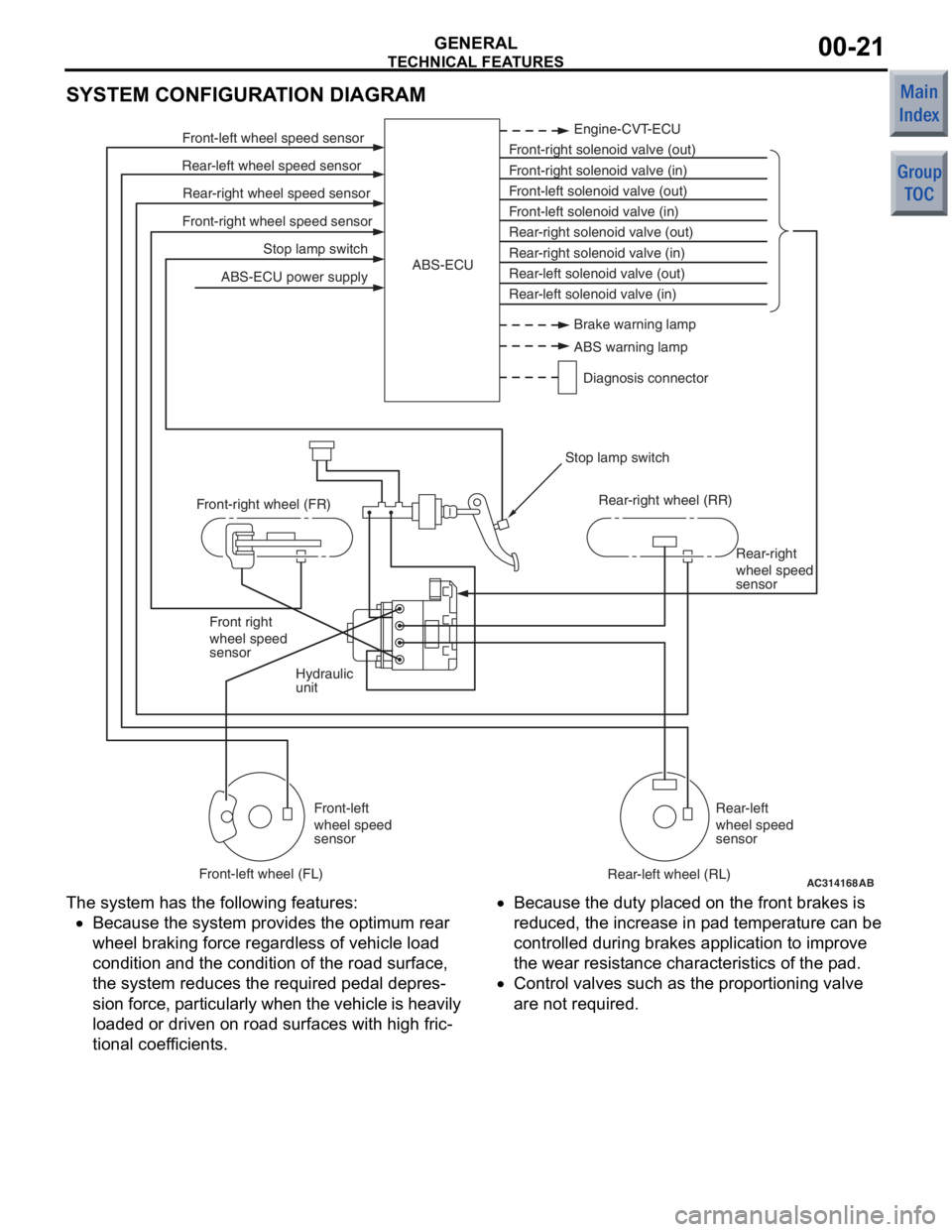
SYSTEM CONFIGURATION DIAGRAM
AC314168
Stop lamp switch
Front-right wheel speed sensor Rear-right wheel speed sensor
Rear-left wheel speed sensor Front-left wheel speed sensor
ABS-ECU power supply Engine-CVT-ECU
Front-right solenoid valve (out)
Front-right solenoid valve (in)
Front-left solenoid valve (out)
Front-left solenoid valve (in)
Rear-right solenoid valve (out)
Rear-right solenoid valve (in)
Rear-left solenoid valve (out)
Rear-left solenoid valve (in)
ABS-ECU
Hydraulic
unit Rear-right
wheel speed
sensor
Front right
wheel speed
sensor
Front-left
wheel speed
sensor Rear-left
wheel speed
sensor
Front-right wheel (FR)
Front-left wheel (FL) Rear-right wheel (RR)
Rear-left wheel (RL)
Stop lamp switch
AB
Brake warning lamp
ABS warning lamp
Diagnosis connector
The syst em has the following features:
•Because the system p rovides t he optimum rea r
wheel braking force regardless of vehicle load
co ndition a nd the condition of the road surface,
the system reduces the required pedal depre s
-
sion fo rce, particularly wh en th e veh icle is h eavily
lo aded o r driven on road surfaces with high fric
-
tional coef ficients.
•Because the duty place d on th e front brakes is
redu ced, th e increase in p ad tempe rature can be
controlled d uring brake s ap plication to impro ve
the we ar resist ance characteristics of the pad.
•Contro l valves such as the propo rtioning valve
are not required.
Page 245 of 364
GROUP 36
PARKING BRAKES
CONTENTS
GENERAL INFORMATION . . . . . . . .36-2
STRUCTURAL DESCRIPTION
. . . . . . . . . . . . . . . . . . . . . . . .36-4
OPERATIONAL DESCRIPTION
. . . . . . . . . . . . . . . . . . . . . . . . .36-5
Page 246 of 364
GENERAL INFORMATION
PARKING BRAKES36-2
GENERAL INFORMATION
M2360000100656
Employment of the parking brake pedal clears front
centre space to allow a walk through design.
PUSH-ON/PUSH-RELEASE type pedal has been
installed for easier operation.
The parking brake pedal retreat suppression mecha-
nism that restraints the retraction of the brake pedal
during collision has been adopted in order to reduce
the shock to the driver's feet. The mechanism of the
parking brake pedal is basically the same as that of
the brake pedal.
NOTE: For more information about brake pedal
retreat suppression mechanism, refer to GROUP
35A, Brake Pedal
P.35A-6.
AC506311AC
Parking brake cable cover
Parking brake pedal assembly
Page 248 of 364
STRUCTURAL DESCRIPTION
PARKING BRAKES36-4
STRUCTURAL DESCRIPTION
M2360000200192
AC207357AB
PawlSector
Release lever
Pawl return spring
Return spring
The pa rking b r ake pedal assemb ly consist s of the
p
a r k ing brake peda l, secto r , rele ase leve r , p a wl
return sprin
g , p a wl, an d return spring. Th e sector is
secured to
the p a rking b r ake pedal bracket b ody .
The p
a wl a nd release lever are f i xe d to the pin axle
by th
e sectio n with a n oblong ho le. Th e p a wl and
release lever
are co nnected by the p a wl returning
spring, an
d move tog e ther with the pedal.
Page 249 of 364

OPERATIONAL DESCRIPTION
PARKING BRAKES36-5
OPERATIONAL DESCRIPTION
M2360000300207
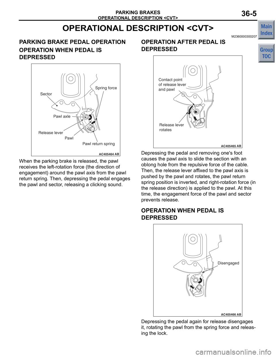
PARKING BRAKE PEDAL OPERATION
OPERATION WHEN PEDAL IS
DEPRESSED
AC405464
Pawl axle
AB
Sector
Release lever
Pawl Pawl return springSpring force
When th
e p a rking bra k e is released, the p a wl
receives the lef
t -rot a tion force (the d i rection o f
engage
ment ) around the p a wl axis from the p a wl
return sprin
g . Then , depre ssing th e peda l eng ages
the p
a wl an d se ctor , relea s ing a clickin g so und.
OPERAT ION AFTER PEDAL IS
DEPRESSED
AC405465
Contact point
of release lever
and pawl
Release lever
rotates
AB
De pressing the pe dal a nd removing on e's fo ot
causes
the p a wl axis to slid e the sect ion with an
oblon
g hole from the re pulsive force of th e cab l e.
Then, t
he release lever af fixe d to th e p a wl axis is
push
ed by the p a wl and rot a te s, the p a wl return
spring position
is inverted, an d r i ght-ro t a t i on force (in
the release dire
ctio n) is appl ied to the p a wl. At this
time
, the e ngage ment force of the p a wl and sect or
preve
n t s release .
OPERAT ION W H EN PEDAL IS
DEPRESSED
AC405466AB
Disengaged
Depressing the pe dal a gain for release disengag es
it, rot
a ting the p a wl from the sprin g force and releas
-
ing the lock.
Page 250 of 364
OPERATIONAL DESCRIPTION
PARKING BRAKES36-6
OPERATION WHEN PEDAL IS
RETURNED
AC405467
Lever
returning
part
AB
When returnin g the p edal, the release lever ret u rns
to the st
arting position from the lever returning se c
-
tion as the spring po sition is inverte d , ca using the
p
a wl to retu rn to th e positio n of release for th e p a rk
-
ing br eak.