2006 MITSUBISHI COLT tensioner
[x] Cancel search: tensionerPage 60 of 364

BASE ENGINE
ENGINE MECHANICAL <4A9>11A-12
TIMING CHAIN TRAIN
AK305075
V.V.T. sprocket
AB
V.V.T. sprocket
timing mark
Timing chain mark
link plate (bule)
Camshaft sprocket
Camshaft sprocket
timing mark Timing chain mark
link plate (bule)
Timing chain mark
link plate (bule)
Crankshaft
sprocket
timing mark
Crankshaft sprocket
Timing mark
Timing chain
tensioner
Tensioner lever
Chain guide
Timing mark
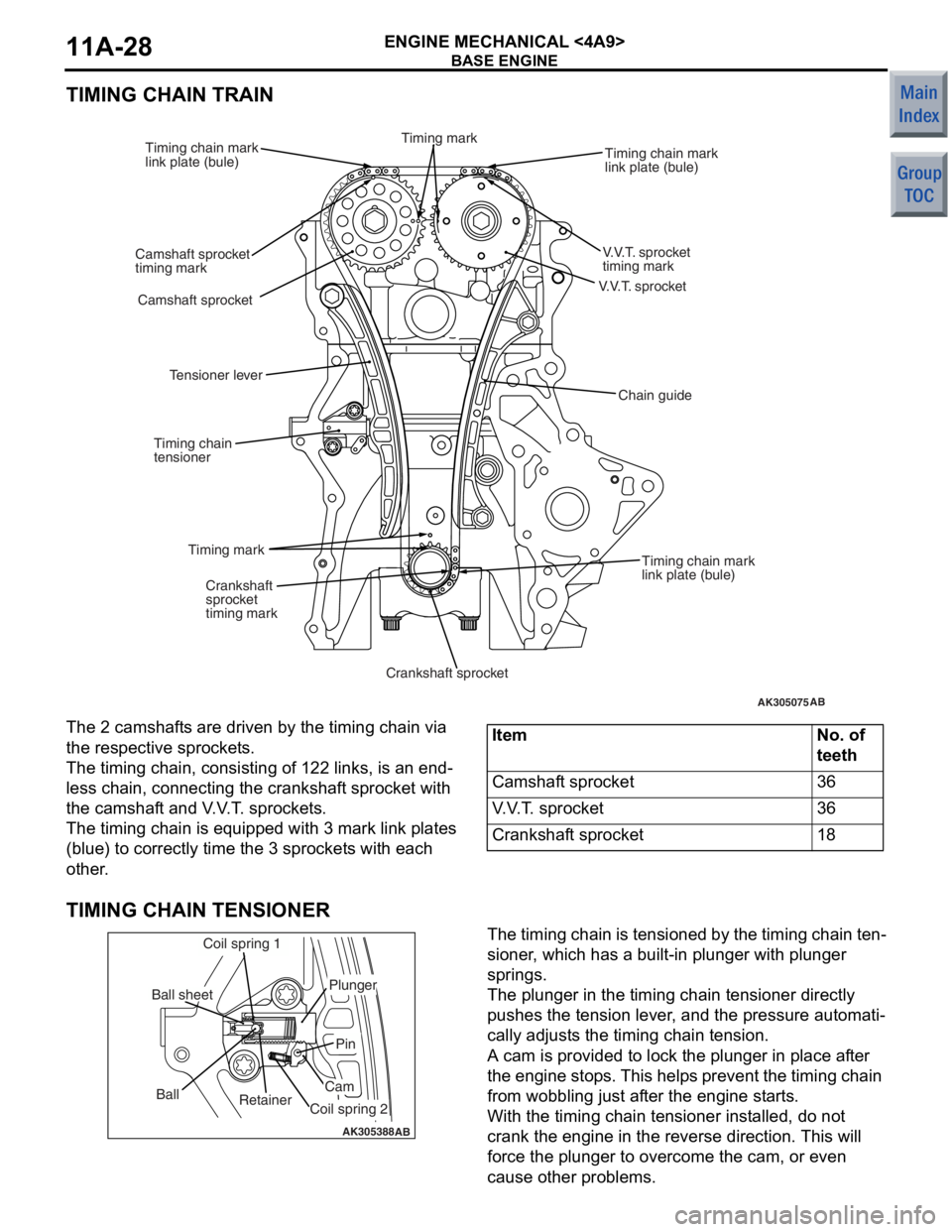
The 2 camshaf
t s are driven by the t i ming chain via
the res
pec tive spro cke t s .
The timing cha i n, consist i ng o f 122 links, is an end-
less chain, conn ecting the cran ksh af t spro cke t with
the camshaf
t and V . V . T . spro cke t s .
The timing cha i n is eq uippe d with 3 mark link p l ates
(blue)
to co rrectly time t he 3 sprocket s with each
other
.
ItemNo. of
teeth
Camshaft sprocket36
V.V.T. sprocket36
Crankshaft sprocket18
TIMING CHAIN TENSIONER
AK305388AB
Retainer
Ball
Coil spring 1
Ball sheet
Coil spring 2
Cam
Pin
Plunger
The timing chain is tensione
d by th e timing chain te n-
sioner , which ha s a b u ilt-in plunge r with plunge r
springs.
The plunger in the timing chain tension e r dire ctly
push
e s th e tension lever , and the pre s sure aut omati
-
cally ad just s the timing chain tension.
A cam is provided t o lock th e plu nger in pla c e a f te r
the eng
ine stop s. This help s prevent the timing chain
from wob
b lin g just af ter th e eng ine st a r t s .
With the timing cha i n ten s io ner in st alled, do not
crank the
engin e in the reverse directio n. This will
force
the plunger to overcome the cam, or e v en
cause oth
e r problems.
Page 76 of 364
BASE ENGINE
ENGINE MECHANICAL <4A9>11A-28
TIMING CHAIN TRAIN
AK305075
V.V.T. sprocket
AB
V.V.T. sprocket
timing mark
Timing chain mark
link plate (bule)
Camshaft sprocket
Camshaft sprocket
timing mark Timing chain mark
link plate (bule)
Timing chain mark
link plate (bule)
Crankshaft
sprocket
timing mark
Crankshaft sprocket
Timing mark
Timing chain
tensioner
Tensioner lever
Chain guide
Timing mark
The 2 camshaf
t s are driven by the t i ming chain via
the res
pec tive spro cke t s .
The timing cha i n, consist i ng o f 122 links, is an end-
less chain, conn ecting the cran ksh af t spro cke t with
the camshaf
t and V . V . T . spro cke t s .
The timing cha i n is eq uippe d with 3 mark link p l ates
(blue)
to co rrectly time t he 3 sprocket s with each
other
.
ItemNo. of
teeth
Camshaft sprocket36
V.V.T. sprocket36
Crankshaft sprocket18
TIMING CHAIN TENSIONER
AK305388AB
Retainer
Ball
Coil spring 1
Ball sheet
Coil spring 2
Cam
Pin
Plunger
The timing chain is tensione
d by th e timing chain te n-
sioner , which ha s a b u ilt-in plunge r with plunge r
springs.
The plunger in the timing chain tension e r dire ctly
push
e s th e tension lever , and the pre s sure aut omati
-
cally ad just s the timing chain tension.
A cam is provided t o lock th e plu nger in pla c e a f te r
the eng
ine stop s. This help s prevent the timing chain
from wob
b lin g just af ter th e eng ine st a r t s .
With the timing cha i n ten s io ner in st alled, do not
crank the
engin e in the reverse directio n. This will
force
the plunger to overcome the cam, or e v en
cause oth
e r problems.
Page 210 of 364
TECHNICAL FEATURES
GENERAL00-25
SUPPLEMENTAL RESTRAINT SYSTEM
(SRS*)
NOTE: *SRS: Supplemental Restraint System
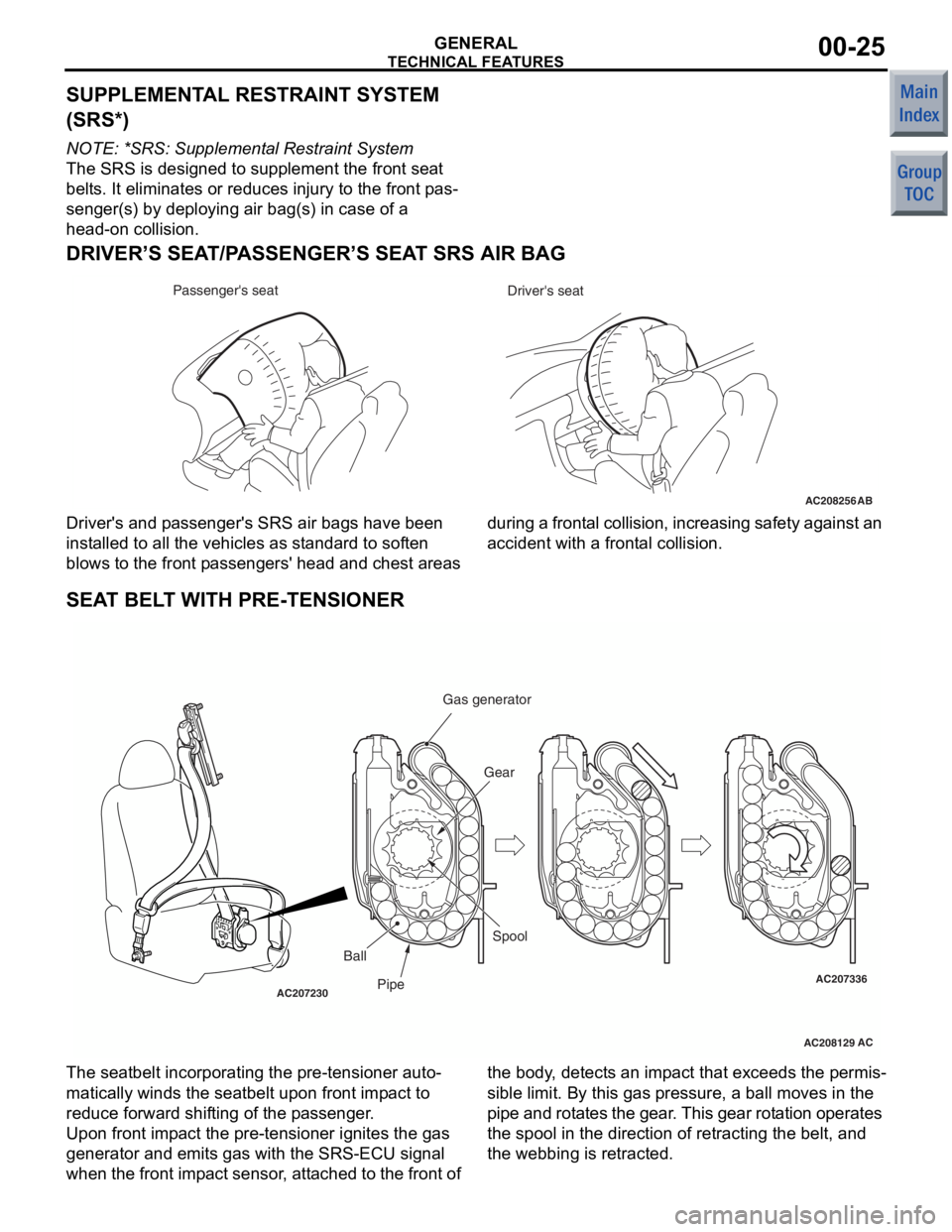
The SRS is designed to supplement the front seat
belts. It eliminates or reduces injury to the front pas
-
senger(s) by deploying air bag(s) in case of a
head-on collision.
DRIVER’S SEAT/PASSENGER’S SEAT SRS AIR BAG
AC208256AB
Driver's seat
Passenger's seat
Driver's and
pa sse nger's SRS a ir bag s have be en
inst alled to all the vehicle s as st andard to sof ten
blows to the front pa sseng ers' head and che st areas d
uring a fro nta l coll ision , i n cre asin g sa fety a gainst an
acciden t with a frontal collision.
SEAT BEL T WITH PRE-TENSIONER
AC208129
AC207230AC207336
ACPipe Gear
Ball Spool
Gas generator
The seatbelt incorpo
rating the pre -tensioner auto-
matically winds the seatbelt upo n front impact to
reduce forward shif ting of the passenge r.
Upo n front impact the pre-ten sion er ig nites the g as
generat or and emits gas with the SRS-ECU signal
whe n t he front imp act sen sor , att ached to the front of the bo
dy, det ects a n imp act t hat excee ds t he pe rmis
-
sible limit. By th is gas p ressure, a ball moves in th e
p ipe and rot ates the ge ar. This gear rotation operate s
the spool in the direction of ret racting the belt, and
the webbing is retr acted.
Page 211 of 364
TECHNICAL FEATURES
GENERAL00-26
SCHEMATIC DIAGRAM
AC508098
Front impact against
another vehicleor
Front impact against a
solid surface Analogue G-sensor
Ignition judgment
Shock
above a
certain
level
Ignition signal
SRS-ECU
Front air bag safing
G-sensor
Front impact
sensor (RH)
Front impact
sensor (LH)
AB
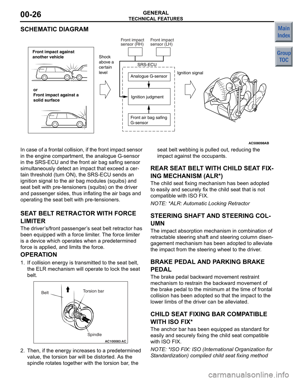
In case of a
frontal collision, if the front imp act sensor
in the engine comp artment, the analogue G-sensor
in the SRS-ECU and t he front air bag safing sensor
simult aneously de tect an imp act th at excee d a cer
-
ta in threshold (turn ON), the SRS-ECU sen ds an
ignition signal to the air bag modules (squ ibs) and
seat belt with pre-te nsioners (squibs) on the driver
and p asseng er sides, thus inflating the air bag s and
operating the seat belt with pre -tensioner s.
SEAT BEL T RETRACT OR WITH FORCE
LIMITE R
The driver ’s /front p asseng er’s seat belt retractor has
been e quipped with a force limit er. The force limiter
is a device which operat es when a predetermined
force is applied, an d limits the for ce.
OPERA TION
1. If collision energy is transmit ted to the seat belt,
th e ELR mechanism will oper ate to lock the seat
be lt.
AC100083
Torsion bar
Spindle
Belt
AC
2.
Then, if the en ergy increase s to a prede termined
value , the to rsion bar will b e distorted . As th e
spind le rot ate s tog ether with the t orsion bar , the seat b
elt webb ing is p ulle d out, reducing th e
imp act against t he occupants.
REAR SEA T BELT WITH CHILD SEA T FIX-
ING MECHANISM (ALR*)
The child seat fixing mechanism h as b een ad opted
to easily and securely fix the child seat that is not
comp atible with ISO FIX.
NO TE: *ALR: Automatic Lockin g Retractor
STEERING SHAFT AND STEERING COL-
UMN
The impact ab sorption mech anism in combin ation of
retract able steerin g shaft and steering co lumn disen
-
gagement mecha nism has been ad opted t o alle viate
the imp act from th e steering wheel to the d rive r.
BRAKE PEDAL AND PA RKING BRAKE
PEDAL
The bra ke pe dal b ackward mo vement restraint
mechanism to restrain the backward movement of
the brake p edal to the minimum at the time o f f ront al
collision h as b een ad opted so that the impact to th e
lower limb s of the driver can be alleviated.
CHILD SEAT FIXING BAR COMP ATIBLE
WITH ISO FIX*
The an chor bar has been equipped a s st andard fo r
easily and secu rely fixing the child seat comp atible
with ISO FIX.
NO TE: *ISO F IX: ISO (In ternational Orga nization for
S tand ardizatio n) complied child se at fixing method
Page 214 of 364

TECHNICAL FEATURES
GENERAL00-29
IMPROVED SERVICEABILITY
•Employment of an automatic hydraulic timing belt
tensioner offers timing belt reliability, reduced
operating noise, and better serviceability. <4G1>
•Wiring harness section of the crank angle sensor
has been moulded integrally with the timing belt
cover, improving serviceability and reliability.
<4G1>
•Due to the adoption of the timing chain and the
timing chain tensioner, maintenance-free and reli
-
ability have been improved. <4A9>
•Since adoption of unvolatile memory (EEPROM*)
helps the learned value not to be initialised when
the battery terminal or connector of the control
unit is disconnected, maintainability can be
improved.
NOTE: *EEPROM: Electrical Erasable Programma-
ble ROM (information to be memorised can be
electronically written into and erased from ROM)
•Since the adoption of electric power steering
makes hydraulic pipes and oil pumps unneces
-
sary, maintainability can be improved.
•Employment of operative A/C piping layout and
refrigerant leak detection system enhances serv
-
iceability.
Page 260 of 364
SEAT BELT
INTERIOR52A-10
SEAT BELT
M2520010000575
AC601600
Seat belt warning lampSeat belt warning lampSeat belt warning lamp
One-touch push bottom type
adjustable seat belt anchorThree-point seat belt
with ELR
Seat belt retractor
with pre-tensioner
and force limiter
Buckle integrated with seat
Centre seat belt
switching mechanism
Seat belt retractor
AC
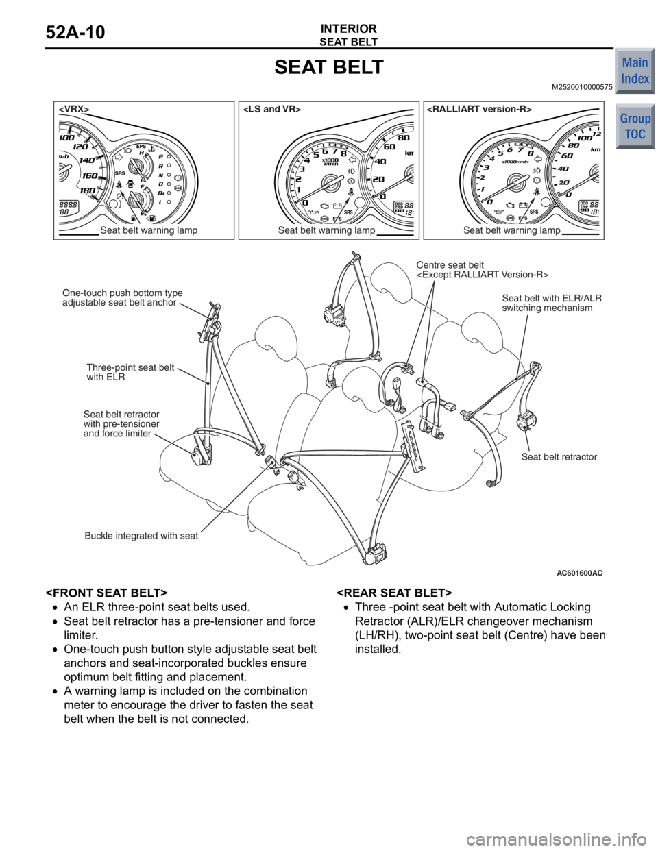
•An ELR three-point se at belt s used.
•Seat be lt re tracto r has a pre-te nsioner a nd force
li
mi ter .
•One-touch pu sh bu tton st yle adjust able se at belt
anchors and seat-inco
r porated buckle s ensure
opt
imu m belt fit t ing a nd placement.
•A warning lamp is included o n the combinat ion
meter to e
n cou r age th e driver to faste n the seat
belt when t
he belt is not conne cted.
•Three -point se at belt with Au tomat i c L o cking
Retractor (ALR)/ELR change
over mechanism
(LH/RH), two-point seat be
lt (Centre ) have been
in
st alled.
Page 293 of 364

GROUP 52B
SUPPLEMENTAL RESTRAINT
SYSTEM (SRS)
CONTENTS
GENERAL INFORMATIO N . . . . . . . .52B-2
SYSTEM OPERATION. . . . . . . . . . . .52B-8
FRONT AIR BAG AND SEAT BELT WITH
PRE-TENSIONER. . . . . . . . . . . . . . . . . . . . 52B-8
SIDE AND CURTAIN AIR BAGS . . . . . . . . 52B-9
SYSTEM CONSTRUCTION . . . . . . . .52B-10
DRIVER'S SIDE AIR BAG MODULE . . . . . 52B-10
PASSENGER'S (FRONT) AIR BAG
MODULE . . . . . . . . . . . . . . . . . . . . . . . . . . . 52B-10
SIDE-AIRBAG MODULE . . . . . . . . . . . . . . . 52B-10
CURTAIN AIR BAG MODULE . . . . . . . . . . . 52B-11
FRONT IMPACT SENSOR . . . . . . . . . . . . . 52B-12
SIDE IMPACT SENSOR . . . . . . . . . . . . . . . 52B-12
SEAT BELT WITH PRE-TENSIONER. . . . . 52B-13
SRS-ECU . . . . . . . . . . . . . . . . . . . . . . . . . . 52B-13
SRS AIR BAG SPECIAL CONNECTOR . . . 52B-17
Page 294 of 364

GENERAL INFORMATION
SUPPLEMENTAL RESTRAINT SYSTEM (SRS)52B-2
GENERAL INFORMATION
M2521000100819
•The driver’s and front passenger’s air bags and
seat belts with pre-tensioner are standard
equipped on all vehicles.
•To improve safety against side impact collisions,
optional side-airbags and curtain air bags are
available to all the models.
•An inflator that does not contain sodium azide is
adopted for all types of the air bag modules.
SRS FRONT AIR BAG
The SRS is designed to supplement the front seat
belts. It reduces injury to the front passenger(s) by
deploying air bag(s) in case of a frontal collision.
SRS SIDE-AIRBAG
Side-airbag systems in the front seats are activated
when side collision applied to the vehicle exceed cri
-
teria to protect the occupants’ upper bodies.
SRS CURTAIN AIR BAG
The curtain air bag systems are activated when side
collision applied to the vehicle exceed criteria, to pro
-
tect the heads of the occupants in the front and rear
seats.
SEAT BELT WITH PRE-TENSIONER
The seat belts with pre-tensioner work simultane-
ously with the SRS. The pre-tensioner takes up seat
belt slack immediately when a collision takes place,
restraining the front passengers sooner than the
SRS. This prevents the passengers from moving for
-
ward.