Page 2 of 364

GENERAL INFORMATION
ANTI-SKID BRAKE SYSTEM (ABS)35B-2
GENERAL INFORMATION
M2351000100409
FEATURES
The ABS ensures directional stability and controlla-
bility during hard braking.
For vehicles with this type of ABS, 4 sensors (4
channels) are installed on front and rear wheels
allowing independent left and right control.
The system has the following features:
•EBD (Electronic Brake-force Distribution system)
control has been added to provide the ideal brak
-
ing force for the rear wheels.
•Magnetic encoder for wheel speed detection has
been installed as a sensing device instead of the
rotor.
•For wiring harness saving and secure data com-
munication, CAN* bus has been adopted as a
tool of communication with another ECU.
NOTE: *: For more information about CAN (Control-
ler Area Network), refer to Group 54C, General Infor-
mation P.54C-2.
EBD CONTROL
In ABS, electronic control is used so the rear wheel
brake hydraulic pressure during braking is regulated
by rear wheel control solenoid valves in accordance
with the vehicle's rate of deceleration, and the front
and rear wheel slippage which are calculated from
the signals received from the various wheel speed
sensors. EBD control provides a high level of control
for both vehicle braking force and vehicle stability.
The system has the following features:
•Because the system provides the optimum rear
wheel braking force regardless of vehicle load
condition and the condition of the road surface,
the system reduces the required pedal depres
-
sion force, particularly when the vehicle is heavily
loaded or driven on road surfaces with high fric
-
tional coefficients.
•Because the duty placed on the front brakes is
reduced, the increase in pad temperature can be
controlled during brakes application to improve
the wear resistance characteristics of the pad.
•Control valves such as the proportioning valve
are not required.
SPECIFICATIONS
ItemSpecification
ABS control method4-sensor, 4-channel
Wheel speed
sensorMagnetic encoderFront86 (N pole:43 S pole:43)
Rear86 (N pole:43 S pole:43)
Ty p eSemiconductor
Page 206 of 364
TECHNICAL FEATURES
GENERAL00-21
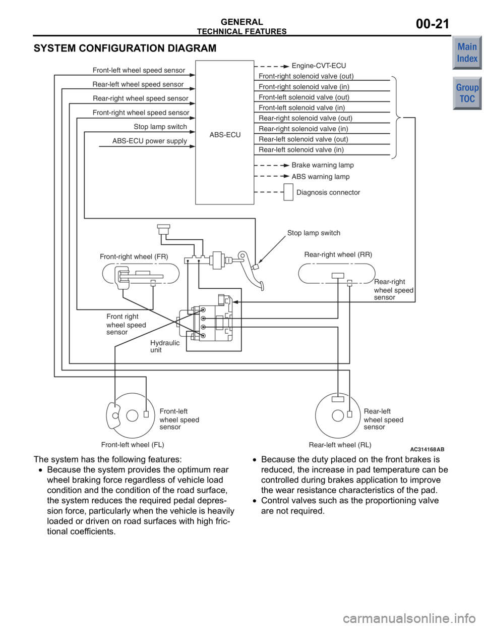
SYSTEM CONFIGURATION DIAGRAM
AC314168
Stop lamp switch
Front-right wheel speed sensor Rear-right wheel speed sensor
Rear-left wheel speed sensor Front-left wheel speed sensor
ABS-ECU power supply Engine-CVT-ECU
Front-right solenoid valve (out)
Front-right solenoid valve (in)
Front-left solenoid valve (out)
Front-left solenoid valve (in)
Rear-right solenoid valve (out)
Rear-right solenoid valve (in)
Rear-left solenoid valve (out)
Rear-left solenoid valve (in)
ABS-ECU
Hydraulic
unit Rear-right
wheel speed
sensor
Front right
wheel speed
sensor
Front-left
wheel speed
sensor Rear-left
wheel speed
sensor
Front-right wheel (FR)
Front-left wheel (FL) Rear-right wheel (RR)
Rear-left wheel (RL)
Stop lamp switch
AB
Brake warning lamp
ABS warning lamp
Diagnosis connector
The syst em has the following features:
•Because the system p rovides t he optimum rea r
wheel braking force regardless of vehicle load
co ndition a nd the condition of the road surface,
the system reduces the required pedal depre s
-
sion fo rce, particularly wh en th e veh icle is h eavily
lo aded o r driven on road surfaces with high fric
-
tional coef ficients.
•Because the duty place d on th e front brakes is
redu ced, th e increase in p ad tempe rature can be
controlled d uring brake s ap plication to impro ve
the we ar resist ance characteristics of the pad.
•Contro l valves such as the propo rtioning valve
are not required.
Page 344 of 364

GENERAL INFORMATION
BASIC BRAKE SYSTEM35A-4
SPECIFICATIONS
ItemSpecifications
Master cylinderTy p eTandem type
I.D. mmLS, VR20.6
VR-X22.2
RALLIART Version-R23.8
Brake boosterTy p eVacuum type, single
Effective dia. of power cylinder mm230
Boosting ratioLS, VR, VR-X6.0 (pedal pressure: 116 N)
7.0 (pedal pressure: 159 N)
RALLIART Version-R6.0 (pedal pressure: 87 N)
7.0 (pedal pressure: 125 N)
Rear wheel hydraulic control methodElectronic brake-force
distribution (EBD)
Front brakesTy p eLS, VRFloating caliper, 1 piston,
ventilated disc (V4-S51)
VR-X, RALLIART Version-RFloating caliper, 1 piston,
ventilated disc (V5-S54)
Disc effective dia. ×
thickness mmLS, VR206 × 20
VR-X226 × 24
RALLIART Version-R232 × 25.8
Cylinder I.D. mmLS, VR50.8
VR-X, RALLIART Version-R54.0
Pad thickness mmLS, VR, VR-X10
RALLIART Version-R10.5
Clearance adjustmentAutomatic
Rear disc brakes
Vers i on -R>
Ty p eVR-XFloating caliper, 1 piston,
solid disc (S4-S30P)
RALLIART Version-RFloating caliper, 1 piston,
solid disc (S4-S34P)
Disc effective dia. ×
thickness mmVR-X224 × 10
RALLIART Version-R200.6 × 10
Cylinder I.D. mmVR-X30.2
RALLIART Version-R34.0
Pad thickness mmVR-X9.5
RALLIART Version-R10.0
Clearance adjustmentAutomatic
Rear drum brakes
Ty p eLeading trailing drum
Drum I.D. mm203
Cylinder I.D. mm19.0
Lining thickness mm4.0
Clearance adjustmentAutomatic
Brake fluidDOT3 or DOT4
Page 347 of 364
CONSTRUCTION DESCRIPTION
BASIC BRAKE SYSTEM35A-7
FRONT BRAKE
M2350003000538
AC403189AE
14-inch disc brake
15-inch disc brake
Pad
Brake disk
Wear indicator When new When worn
Conventional structure
Caliper support
bracket Knuckle
•Ventilate d disc b r ake (V4−S51 or V5−S54) is
in
st
alled.
•The callipe r sup port bra c ket int egrated with the
kn
uckle h a s be en in st alled, achie v in g weigh t
redu
ction and optimising it for b r ake perform
-
ance.
•Audible wear indicat o r that informs th e driver of
wear limit is inst
alle d to th e inn e r brake p ad.
(Only lef
t side)
DISC BRAKE DESIGNA T ION
S 4 - S 30 P
1 2 3 4 5
AC403539
No.ItemContent
1Brake disc typeV: Ventilated
2Brake size
(Minimum applicable
disc wheel)4: 14-inch
5: 15-inch
3No. of pistonS: 1piston (floating type)
4Piston size (rounded
to nearest integer)30: φ 30 mm
34: φ 34 mm
51: φ 51 mm
54: φ 54 mm
5Parking brake
mechanismP: Set
