Page 247 of 2305
TEST ACTION APPLICABILITY
3 Disconnect the Sentry Key Remote Entry Module connector.
Disconnect the Security System Module C2 connector.
Measure the resistance between ground and the Security System Interface circuit.
Is the resistance below 20000.0 ohms?All
Ye s!Repair the Security System Interface circuit for a short to ground.
Perform BODY VERIFICATION TEST - VER 1.
No!Go To 4
4 Disconnect the Sentry Key Remoter Entry connector.
Disconnect the Security System Module C2 connector.
Measure the resistance of the Security System circuit between the SSM C2 connector
and the CTM C1 connector..
Is the resistance below 5.0 ohms?All
Ye s!Replace the Security System Module.
Perform BODY VERIFICATION TEST - VER 1.
No!Repair the Security System Interface circuit for an open.
Perform BODY VERIFICATION TEST - VER 1.
234
VEHICLE THEFT/SECURITY
SECURITY SYSTEM INTERFACE FAILURE - SSM ÐContinued
Page 248 of 2305

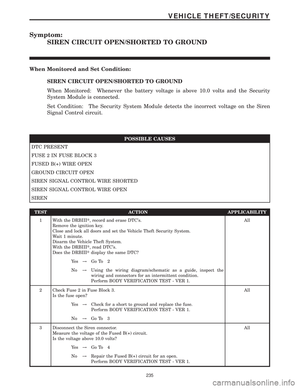
Symptom:
SIREN CIRCUIT OPEN/SHORTED TO GROUND
When Monitored and Set Condition:
SIREN CIRCUIT OPEN/SHORTED TO GROUND
When Monitored: Whenever the battery voltage is above 10.0 volts and the Security
System Module is connected.
Set Condition: The Security System Module detects the incorrect voltage on the Siren
Signal Control circuit.
POSSIBLE CAUSES
DTC PRESENT
FUSE 2 IN FUSE BLOCK 3
FUSED B(+) WIRE OPEN
GROUND CIRCUIT OPEN
SIREN SIGNAL CONTROL WIRE SHORTED
SIREN SIGNAL CONTROL WIRE OPEN
SIREN
TEST ACTION APPLICABILITY
1 With the DRBIIIt, record and erase DTC's.
Remove the ignition key.
Close and lock all doors and set the Vehicle Theft Security System.
Wait 1 minute.
Disarm the Vehicle Theft System.
With the DRBIIIt, read DTC's.
Does the DRBIIItdisplay the same DTC?All
Ye s!Go To 2
No!Using the wiring diagram/schematic as a guide, inspect the
wiring and connectors for an intermittent condition.
Perform BODY VERIFICATION TEST - VER 1.
2 Check Fuse 2 in Fuse Block 3.
Is the fuse open?All
Ye s!Check for a short to ground and replace the fuse.
Perform BODY VERIFICATION TEST - VER 1.
No!Go To 3
3 Disconnect the Siren connector.
Measure the voltage of the Fused B(+) circuit.
Is the voltage above 10.0 volts?All
Ye s!Go To 4
No!Repair the Fused B(+) circuit for an open.
Perform BODY VERIFICATION TEST - VER 1.
235
VEHICLE THEFT/SECURITY
Page 250 of 2305

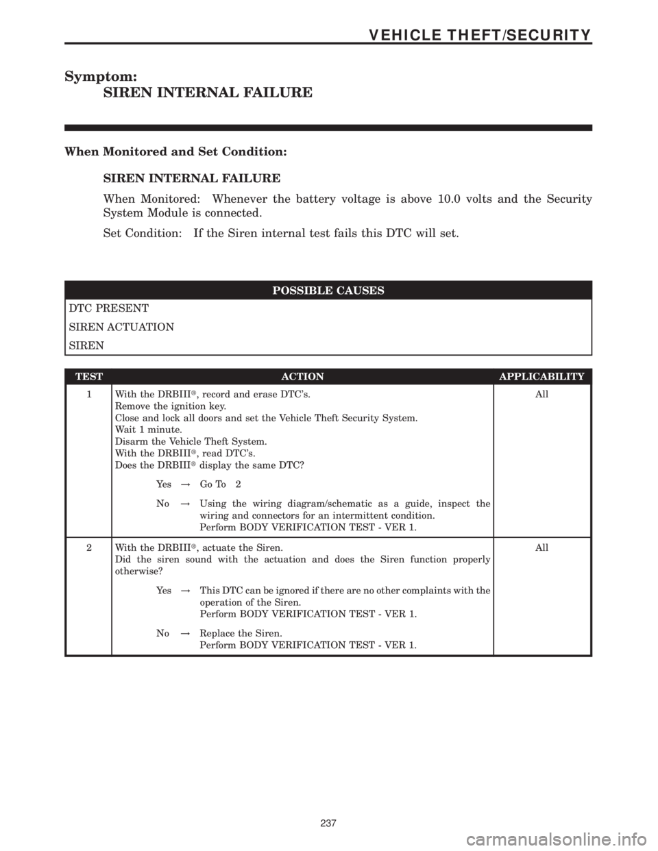
Symptom:
SIREN INTERNAL FAILURE
When Monitored and Set Condition:
SIREN INTERNAL FAILURE
When Monitored: Whenever the battery voltage is above 10.0 volts and the Security
System Module is connected.
Set Condition: If the Siren internal test fails this DTC will set.
POSSIBLE CAUSES
DTC PRESENT
SIREN ACTUATION
SIREN
TEST ACTION APPLICABILITY
1 With the DRBIIIt, record and erase DTC's.
Remove the ignition key.
Close and lock all doors and set the Vehicle Theft Security System.
Wait 1 minute.
Disarm the Vehicle Theft System.
With the DRBIIIt, read DTC's.
Does the DRBIIItdisplay the same DTC?All
Ye s!Go To 2
No!Using the wiring diagram/schematic as a guide, inspect the
wiring and connectors for an intermittent condition.
Perform BODY VERIFICATION TEST - VER 1.
2 With the DRBIIIt, actuate the Siren.
Did the siren sound with the actuation and does the Siren function properly
otherwise?All
Ye s!This DTC can be ignored if there are no other complaints with the
operation of the Siren.
Perform BODY VERIFICATION TEST - VER 1.
No!Replace the Siren.
Perform BODY VERIFICATION TEST - VER 1.
237
VEHICLE THEFT/SECURITY
Page 251 of 2305

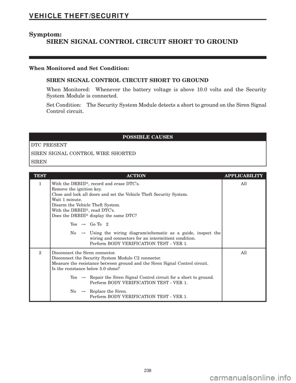
Symptom:
SIREN SIGNAL CONTROL CIRCUIT SHORT TO GROUND
When Monitored and Set Condition:
SIREN SIGNAL CONTROL CIRCUIT SHORT TO GROUND
When Monitored: Whenever the battery voltage is above 10.0 volts and the Security
System Module is connected.
Set Condition: The Security System Module detects a short to ground on the Siren Signal
Control circuit.
POSSIBLE CAUSES
DTC PRESENT
SIREN SIGNAL CONTROL WIRE SHORTED
SIREN
TEST ACTION APPLICABILITY
1 With the DRBIIIt, record and erase DTC's.
Remove the ignition key.
Close and lock all doors and set the Vehicle Theft Security System.
Wait 1 minute.
Disarm the Vehicle Theft System.
With the DRBIIIt, read DTC's.
Does the DRBIIItdisplay the same DTC?All
Ye s!Go To 2
No!Using the wiring diagram/schematic as a guide, inspect the
wiring and connectors for an intermittent condition.
Perform BODY VERIFICATION TEST - VER 1.
2 Disconnect the Siren connector.
Disconnect the Security System Module C2 connector.
Measure the resistance between ground and the Siren Signal Control circuit.
Is the resistance below 5.0 ohms?All
Ye s!Repair the Siren Signal Control circuit for a short to ground.
Perform BODY VERIFICATION TEST - VER 1.
No!Replace the Siren.
Perform BODY VERIFICATION TEST - VER 1.
238
VEHICLE THEFT/SECURITY
Page 266 of 2305
8.8.2 SENTRY KEY REMOTE ENTRY MODULE
8.8.3 DOOR LOCK MOTOR/AJAR SWITCH
8.8.4 CONTACT PLATES
C
O
M
P
O
N
E
N
T
L
O
C
A
T
I
O
N
S
253
COMPONENT LOCATIONS
Page 291 of 2305
FUSES (FUSE/RELAY BLOCK)FUSE
NO.AMPS FUSED CIRCUIT FUNCTION
1 30A 14BL/YL FUSED B(+)
2- - -
3- - -
4- - -
5 10A 16RD/YL FUSED B(+)
6 7.5A 18BK/RD FUSED OPTIONAL EQUIPMENT RELAY OUTPUT
7 25A 14RD FUSED B(+)
8 40A 12RD FUSED B(+)
9 40A 12RD FUSED B(+)
10 30A 12RD/GY FUSED B(+)
HOOD AJAR SWITCH - BLACKCAV CIRCUIT FUNCTION
1 16BK/BL HOOD AJAR SWITCH SENSE
2- -
3 16BR GROUND
HORN (VTSS)CAV CIRCUIT FUNCTION
1 16BK/BR HORN RELAY OUTPUT
2 16BK/YL FUSED IGNITION SWITCH OUTPUT (RUN-START)
IGNITION LOCK SWITCH - BLACKCAV CIRCUIT FUNCTION
1 20BR GROUND
2 20BL/BK KEY-IN IGNITION SWITCH SIGNAL
C
O
N
N
E
C
T
O
R
P
I
N
O
U
T
S
278
CONNECTOR PINOUTS
Page 292 of 2305

INSTRUMENT CLUSTER C1CAV CIRCUIT FUNCTION
1 20BR FUEL LEVEL SENSOR SIGNAL RETURN
2 20BR/DG AMBIENT TEMPERATURE SENSOR SIGNAL RETURN
4 20WT/GY K-IC/ATC/HBM/CHM
5 20BR/BK PARK BRAKE INDICATOR SIGNAL
7 20BK/DG RIGHT TURN SIGNAL
10 20BL/BK FUEL LEVEL SENSOR SIGNAL (+)
11 20BL/DG AMBIENT TEMPERATURE SENSOR SIGNAL (+)
14 20DG/WT/BL ENGINE COOLANT LEVEL SWITCH SIGNAL
15 20BR/WT FRONT COURTESY LAMPS CONTROL
16 20YL/RD SEAT BELT SWITCH SIGNAL
17 20DG CAN C BUS (-)
18 20DG/WT CAN C BUS (+)
INSTRUMENT CLUSTER C2 - WHITECAV CIRCUIT FUNCTION
1- -
2- -
3 20RD/YL FUSED B(+)
4 20BR/WT BRAKE WEAR SENSOR SIGNAL
5- -
6 18BR GROUND
7 20GY/DG/RD LAMP DRIVER
8 20BL/WT FUSED HIGH BEAM SWITCH OUTPUT
9 20BL/RD/WT VEHICLE SPEED SENSOR OUTPUT
10 20BK FUSED IGNITION SWITCH OUTPUT (RUN-START)
11 20BL/BK KEY-IN IGNITION SWITCH SIGNAL
12 - -
13 20BK/WT LEFT TURN SIGNAL
14 20BR/YL BRAKE FLUID LEVEL INDICATOR SIGNAL
15 20BL GENERATOR FIELD DRIVER
16 20YL AIRBAG WARNING INDICATOR DRIVER
17 - -
18 20BL/VT D(+) RELAY NO. 1 CONTROL
18 20BL/VT D(+) RELAY NO. 1 CONTROL
INTRUSION SENSOR NO. 1 - BLACKCAV CIRCUIT FUNCTION
1 20BR GROUND
2 20DG/BK INTRUSION SENSOR 1 SIGNAL
3 20DG/YL INTRUSION SENSOR INTERFACE
4 20RD/DG FUSED B(+)
INTRUSION SENSOR NO. 2 - BLACKCAV CIRCUIT FUNCTION
1 20BR GROUND
2 20GY/BK INTRUSION SENSOR 2 SIGNAL
3 20DG/YL INTRUSION SENSOR INTERFACE
4 20RD/DG FUSED B(+)
C
O
N
N
E
C
T
O
R
P
I
N
O
U
T
S
279
CONNECTOR PINOUTS
Page 297 of 2305

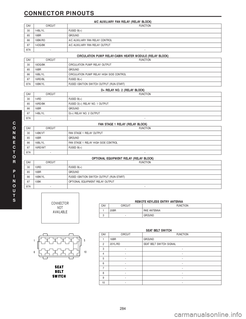
A/C AUXILIARY FAN RELAY (RELAY BLOCK)CAV CIRCUIT FUNCTION
30 14BL/YL FUSED B(+)
85 18BR GROUND
86 18BK/RD A/C AUXILIARY FAN RELAY CONTROL
87 14DG/BK A/C AUXILIARY FAN RELAY OUTPUT
87A --
CIRCULATION PUMP RELAY-CABIN HEATER MODULE (RELAY BLOCK)CAV CIRCUIT FUNCTION
30 18DG/BK CIRCULATION PUMP RELAY OUTPUT
85 16BR GROUND
86 16BL/YL CIRCULATION PUMP RELAY HIGH SIDE CONTROL
87 16RD/BL FUSED B(+)
87A 16BK/YL FUSED IGNITION SWITCH OUTPUT (RUN-START)
D+ RELAY NO. 2 (RELAY BLOCK)CAV CIRCUIT FUNCTION
30 14RD FUSED B(+)
85 16RD/BK FUSED D(+) RELAY NO. 1 OUTPUT
86 16BR GROUND
87 14BL/YL D(+) RELAY NO. 2 OUTPUT
87A --
FAN STAGE 1 RELAY (RELAY BLOCK)CAV CIRCUIT FUNCTION
30 14BK/VT FAN STAGE 1 RELAY OUTPUT
85 16BR GROUND
86 16BL/YL FAN STAGE 1 RELAY HIGH SIDE CONTROL
87 16RD/WT FUSED B(+)
87A --
OPTIONAL EQUIPMENT RELAY (RELAY BLOCK)CAV CIRCUIT FUNCTION
30 10RD FUSED B(+)
85 16BR GROUND
86 16BK/YL FUSED IGNITION SWITCH OUTPUT (RUN-START)
87 10BK OPTIONAL EQUIPMENT RELAY OUTPUT
87A --
REMOTE KEYLESS ENTRY ANTENNACAV CIRCUIT FUNCTION
1 20BR RKE ANTENNA
3 - GROUND
SEAT BELT SWITCHCAV CIRCUIT FUNCTION
1 16BR GROUND
2 20YL/RD SEAT BELT SWITCH SIGNAL
3- -
4- -
5- -
6- -
7- -
8- -
9- -
10 - -
C
O
N
N
E
C
T
O
R
P
I
N
O
U
T
S
284
CONNECTOR PINOUTS