2006 MERCEDES-BENZ SPRINTER key
[x] Cancel search: keyPage 2172 of 2305
²Disconnect the live test lead before disconnecting
the common test lead.
²When using the meter function, keep the
DRBIIItaway from spark plug or coil wires to
avoid measuring error from outside interference.
4.3 WARNINGS
4.3.1 VEHICLE DAMAGE WARNINGS
Before disconnecting any control module, make
sure the ignition is9lock9position. Failure to do so
could damage the module.
When testing voltage or continuity at any control
module, use the terminal side (not the wire end) of
the connector. Do not probe a wire through the
insulation: this will damage the wire and eventu-
ally cause the wire to fail because of corrosion.
Be careful when performing electrical tests so as
to prevent accidental shorting of terminals. Such
mistakes can damage fuses or components. Also, a
second DTC could be set, making diagnosis of the
original problem more difficult.
When replacing a blown fuse, it is important to
use only a fuse having the correct amperage rating.
The use of a fuse with a rating other than indicated
may result in a dangerous electrical system over-
load. If a properly rated fuse continues to blow, it
indicates a problem in the circuit that must be
corrected.
4.3.2 ROAD TESTING A COMPLAINT
VEHICLE
Some complaints will require a test drive as part
of the repair verification procedure. The purpose of
the test drive is to try to duplicate the diagnostic
DTC or symptom condition.
CAUTION: Before road testing a vehicle, be
sure that all components are reassembled.
During the test drive, do not try to read
DRBIIITscreen while in motion. Do not hang
the DRBIIITfrom the rear view mirror or
operate it yourself. Have an assistant
available to operate the DRBIIIT.
Road testing is an essential step in the diagnostic
process that must not be overlooked. Along with the
diagnostic information obtained from the DRBIIIt
Scan Tool and the original customer concern, the
road test helps verify the problem was current and
any repairs performed, fixed the vehicle correctly.
Always operate and observe the vehicle under ac-
tual driving conditions.
Just as important as the road test is, there are
preliminary inspections that should be performed
prior to the road test. Always check the fluid leveland condition before taking the vehicle on a road
test. Determine if the incorrect fluid is being used,
improper fluid will result in erratic transmission
operation.
Some of the conditions of incorrect fluid level are as
follows:
²Delayed engagement
²Poor shifting or erratic shifting
²Excessive noise
²Overheating
The next step is to verify that the shift linkage is
correctly adjusted. If the shift linkage is incorrectly
adjusted, a number of complaints can result.
The TCM monitors the Shift Lever Position (SLP)
continuously. If the linkage is incorrectly adjusted,
the TCM will sense a shift lever position that is not
correct for the gear chosen by the driver. This may
cause a DTC to be set.
The following complaints may also be the result of
an incorrectly adjusted or worn linkage:
²Delayed clutch engagement
²Erratic shifts
²Vehicle will drive in neutral
²Engine will not crank in park or neutral
²Gear shift linkage will be able to be shifted
without the key in the ignition
²Not able to remove the ignition key in park
²Parking pawl will not engage properly
The shift linkage should also be adjusted when
replacing the Transmission, repairing the valve
body, or when repairing any component between the
shift lever and the Transmission.
Some questions to ask yourself when performing
the road test are as follows:
²Is the complaint or concern what you think the
problem is, based on the drivers description of the
problem?
²Is the Transmission operating normally, or is
there a real problem?
²When does the problem occur?
²Is the problem only in one gear range?
²What temperature does the problem occur?
²Does the vehicle have to sit over night for the
problem to occur?
²Does the transmission go into Limp-in mode?
4.4.4 BULLETINS AND RECALLS
Always perform all Safety Recalls and Technical
Service Bulletins that are applicable to the prob-
lem.
7
GENERAL INFORMATION
Page 2173 of 2305
5.0 REQUIRED TOOLS AND
EQUIPMENT
> DRBIIIt(diagnostic read-out box) - DRBIIIt
must use the latest release level.
> Jumper wires
> Test Light
> Ohmmeter
> Voltmeter
6.0 GLOSSARY OF TERMS
6.1 ACRONYMS
ABSAntilock Braking system
A/CAir conditioner
A/DAnalog to Digital conversion
APPAccelerator Pedal Position
CANController Area Network (Vehicle
Bus System)
CKTCircuit
DLCData Link Connector
DRBIIItDiagnostic Readout Box
DTCDiagnostic Trouble Code
ECMDiesel Engine Controller
EMCCElectronically Modulated Converter
Clutch
IODIgnition off-draw
ISSInput Speed Sensor (N2 and N3)
KK line communication bus
LEDLight Emitting Diode
MILMalfunction Indicator LampOSSOutput Speed Sensor (derived from
the ABS controller)
PEMCCPartial Electronically Modulated
Converter Clutch
PWMPulse width modulated
SKREEMSentry Key Remote Entry Module
SLAShift Lever Assembly
SWSwitch
TCCTorque Converter Clutch
TCMTransmission Control Module
TPThrottle Position
TRDTorque Reduction
TTSTransmission Temperature Sensor
1-2/4-5
solenoidcontrols the shift into and out of
2nd gear or 5th gear.
V2-3 so-
lenoidcontrols the shift into and out of 3rd
gear
V3-4 so-
lenoidcontrols the shift into and out of 4th
gear
VTCC
solenoidis pulse width modulated and con-
trols the TCC clutch
Shift
Pressure
Solenoidis a pulse width modulated solenoid
and controls the hydraulic pressure
to the shift elements.
Modula-
tion
pressure
solenoidis a pulse width modulated solenoid
and controls the hydraulic system
pressure
6.2 DEFINITIONS
Driving cycle counter) -The starts since first set
counter indicates the number of driving cycles since
the first occurrence of an error.
8
GENERAL INFORMATION
Page 2201 of 2305
Symptom:
ABS CAN MESSAGE MISSING
When Monitored and Set Condition:
ABS CAN MESSAGE MISSING
When Monitored: CAN Bus Circuit error not present, 1 second after ignition on and not
in Park or Neutral, no System Overvoltage or System Undervoltage conditions present, or
transmission in Park or Neutral and engine RPM greater than 850 RPM
Set Condition: This DTC is set when a CAN ID was not received in the required time are
not being sent from the ABS Controller. NOTE: The ABS controller is powered by the run
only ignition feed. This means that this DTC will be set if the key is placed in the start
position with the transmission in gear or if in Park or Neutral and the engine RPM is
greater than 850 RPM.
POSSIBLE CAUSES
CAN BUS CIRCUIT DTC PRESENT
CAN BUS +/- CIRCUIT OPEN
ABS DTCS PRESENT
ABS - CAN MESSAGE MISSING
TCM - CAN MESSAGE MISSING
TEST ACTION APPLICABILITY
1NOTE: Low fluid level can be the cause of many transmission problems. If
the fluid level is low locate and repair the leak then check and adjust the
fluid level per the service information.
NOTE: Always perform diagnostics with a fully charged battery to avoid
false symptoms.
With the DRBIIIt, read the engine DTCs. Check and repair all engine DTCs prior to
performing transmission symptom diagnostics.
With the DRBIIIt, read and record all Transmission DTCs.
NOTE: Check connectors - Clean/repair as necessary. Poor pin to terminal
connections can set DTCs.
Using the wiring diagram/schematic as a guide, inspect the wiring and connectors.
Repair as necessary.
Most DTCs set on start up but some must be set by driving the vehicle such that all
diagnostic monitors have run.
Note: Verify flash level of transmission controller. Some problems are
corrected by software upgrades to the transmission controller.
NOTE: Check for any Technical Service Bulletins that may apply.
Perform this procedure prior to Symptom diagnosis.All
Continue
Go To 2
36
TRANSMISSION - NAG1
Page 2213 of 2305
Symptom:
CAN BUS CIRCUIT
When Monitored and Set Condition:
CAN BUS CIRCUIT
When Monitored: Always monitored with system active at each ignition cycle.
Set Condition: Open circuit in the CAN C Bus (+) circuit or CAN C Bus (-) circuit, Short
to ground of CAN C Bus (+) circuit or CAN C Bus (-) circuit, Short to Voltage of CAN C Bus
(+) circuit or CAN C Bus (-) circuit, CAN C Bus (+) circuit shorted to CAN C Bus (-) circuit,
or a TCM failure. Note: All CAN message missing DTCS will also be present, which
indicates a Bus Failure.
POSSIBLE CAUSES
CAN BUS CIRCUITS OPEN TO SKREEM OR ECM
CAN BUS CIRCUITS OPEN TO TCM
CAN CIRCUITS SHORTED TO GROUND
CAN CIRCUIT SHORT TO VOLTAGE
CAN CIRCUITS SHORTED TOGETHER
MODULE SHORT INTERNALLY
MODULE SHORT TO GROUND
MODULE SHORT TO VOLTAGE
ECM - TERMINATING RESISTOR
SENTRY KEY REMOTE ENTRY MODULE
TRANSMISSION CONTROL MODULE
48
TRANSMISSION - NAG1
Page 2217 of 2305
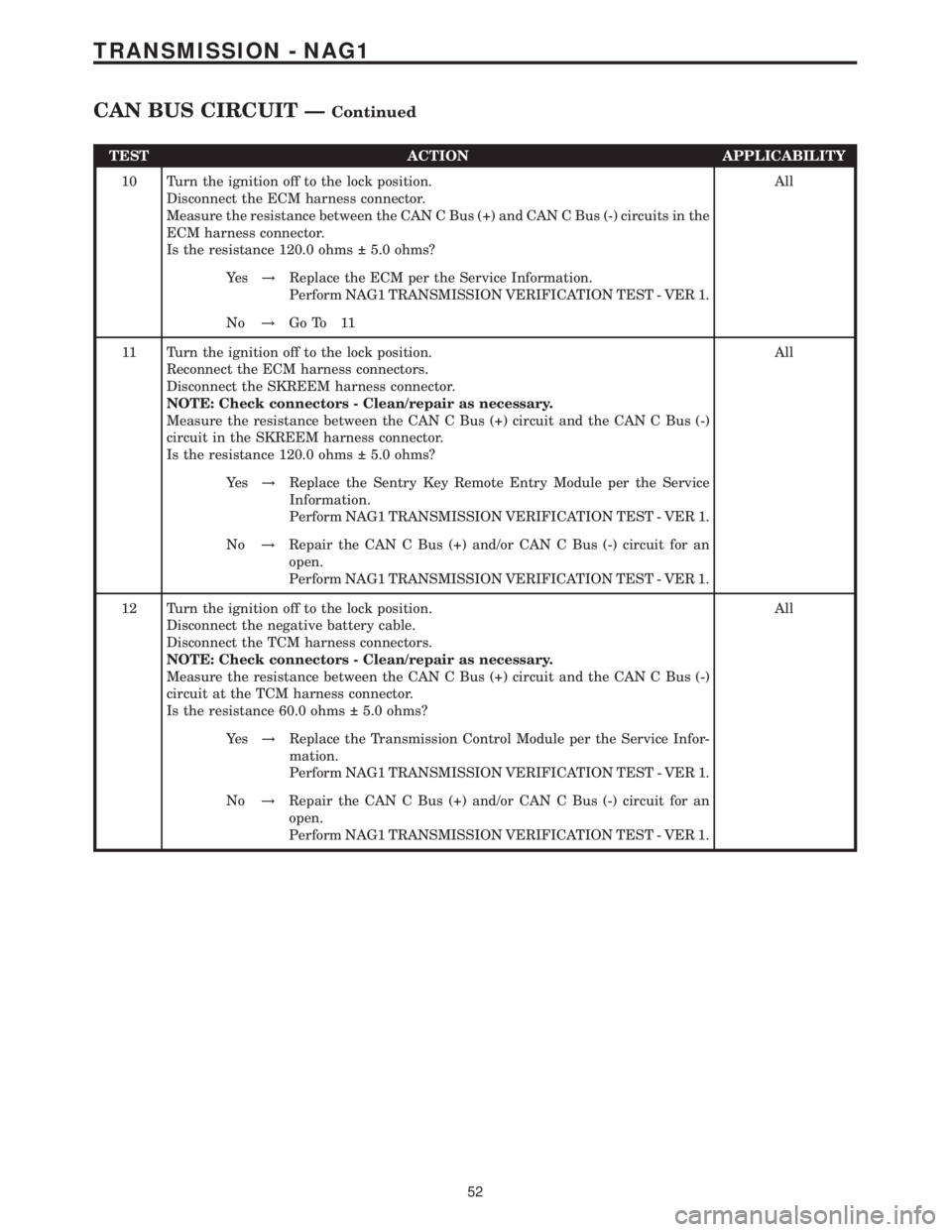
TEST ACTION APPLICABILITY
10 Turn the ignition off to the lock position.
Disconnect the ECM harness connector.
Measure the resistance between the CAN C Bus (+) and CAN C Bus (-) circuits in the
ECM harness connector.
Is the resistance 120.0 ohms 5.0 ohms?All
Ye s!Replace the ECM per the Service Information.
Perform NAG1 TRANSMISSION VERIFICATION TEST - VER 1.
No!Go To 11
11 Turn the ignition off to the lock position.
Reconnect the ECM harness connectors.
Disconnect the SKREEM harness connector.
NOTE: Check connectors - Clean/repair as necessary.
Measure the resistance between the CAN C Bus (+) circuit and the CAN C Bus (-)
circuit in the SKREEM harness connector.
Is the resistance 120.0 ohms 5.0 ohms?All
Ye s!Replace the Sentry Key Remote Entry Module per the Service
Information.
Perform NAG1 TRANSMISSION VERIFICATION TEST - VER 1.
No!Repair the CAN C Bus (+) and/or CAN C Bus (-) circuit for an
open.
Perform NAG1 TRANSMISSION VERIFICATION TEST - VER 1.
12 Turn the ignition off to the lock position.
Disconnect the negative battery cable.
Disconnect the TCM harness connectors.
NOTE: Check connectors - Clean/repair as necessary.
Measure the resistance between the CAN C Bus (+) circuit and the CAN C Bus (-)
circuit at the TCM harness connector.
Is the resistance 60.0 ohms 5.0 ohms?All
Ye s!Replace the Transmission Control Module per the Service Infor-
mation.
Perform NAG1 TRANSMISSION VERIFICATION TEST - VER 1.
No!Repair the CAN C Bus (+) and/or CAN C Bus (-) circuit for an
open.
Perform NAG1 TRANSMISSION VERIFICATION TEST - VER 1.
52
TRANSMISSION - NAG1
CAN BUS CIRCUIT ÐContinued