2006 MERCEDES-BENZ SPRINTER key
[x] Cancel search: keyPage 1735 of 2305
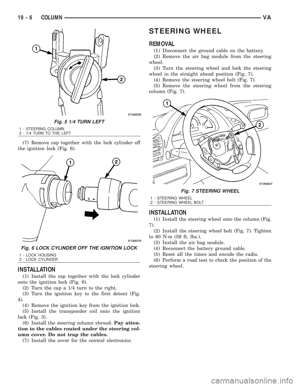
(7) Remove cap together with the lock cylinder off
the ignition lock (Fig. 6).
INSTALLATION
(1) Install the cap together with the lock cylinder
onto the ignition lock (Fig. 6).
(2) Turn the cap a 1/4 turn to the right.
(3) Turn the ignition key to the first detent (Fig.
4).
(4) Remove the ignition key from the ignition lock.
(5) Install the transponder coil onto the ignition
lock (Fig. 3).
(6) Install the steering column shroud.Pay atten-
tion to the cables routed under the steering col-
umn cover. Do not trap the cables.
(7) Install the cover for the central electronics.
STEERING WHEEL
REMOVAL
(1) Disconnect the ground cable on the battery.
(2) Remove the air bag module from the steering
wheel.
(3) Turn the steering wheel and lock the steering
wheel in the straight ahead position (Fig. 7).
(4) Remove the steering wheel bolt (Fig. 7).
(5) Remove the steering wheel from the steering
column (Fig. 7).
INSTALLATION
(1) Install the steering wheel onto the column (Fig.
7).
(2) Install the steering wheel bolt (Fig. 7). Tighten
to 80 N´m (59 ft. lbs.).
(3) Install the air bag module.
(4) Reconnect the battery ground cable.
(5) Reset all the times and encode the radio.
(6) Perform a road test to check the position of the
steering wheel.
Fig. 5 1/4 TURN LEFT
1 - STEERING COLUMN
2 - 1/4 TURN TO THE LEFT
Fig. 6 LOCK CYLINDER OFF THE IGNITION LOCK
1 - LOCK HOUSING
2 - LOCK CYLINDER
Fig. 7 STEERING WHEEL
1 - STEERING WHEEL
2 - STEERING WHEEL BOLT
19 - 6 COLUMNVA
Page 1911 of 2305
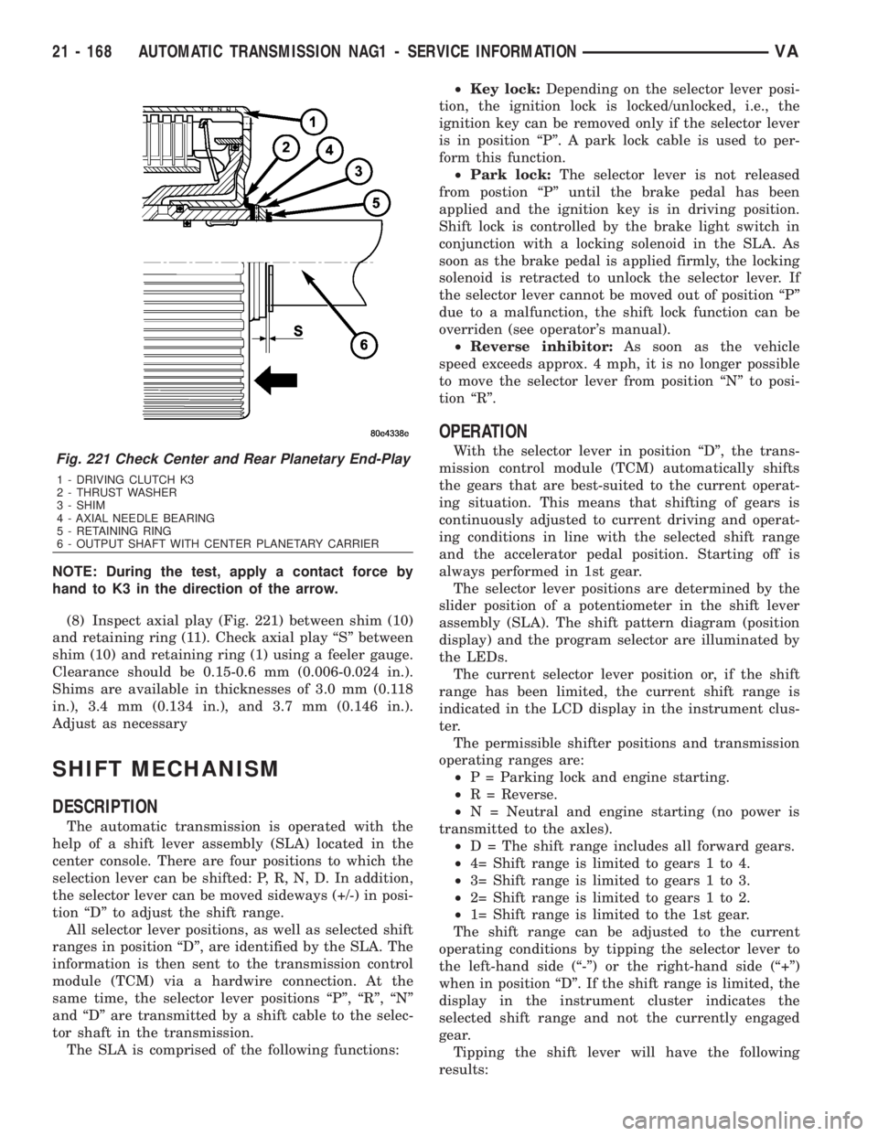
NOTE: During the test, apply a contact force by
hand to K3 in the direction of the arrow.
(8) Inspect axial play (Fig. 221) between shim (10)
and retaining ring (11). Check axial play ªSº between
shim (10) and retaining ring (1) using a feeler gauge.
Clearance should be 0.15-0.6 mm (0.006-0.024 in.).
Shims are available in thicknesses of 3.0 mm (0.118
in.), 3.4 mm (0.134 in.), and 3.7 mm (0.146 in.).
Adjust as necessary
SHIFT MECHANISM
DESCRIPTION
The automatic transmission is operated with the
help of a shift lever assembly (SLA) located in the
center console. There are four positions to which the
selection lever can be shifted: P, R, N, D. In addition,
the selector lever can be moved sideways (+/-) in posi-
tion ªDº to adjust the shift range.
All selector lever positions, as well as selected shift
ranges in position ªDº, are identified by the SLA. The
information is then sent to the transmission control
module (TCM) via a hardwire connection. At the
same time, the selector lever positions ªPº, ªRº, ªNº
and ªDº are transmitted by a shift cable to the selec-
tor shaft in the transmission.
The SLA is comprised of the following functions:²Key lock:Depending on the selector lever posi-
tion, the ignition lock is locked/unlocked, i.e., the
ignition key can be removed only if the selector lever
is in position ªPº. A park lock cable is used to per-
form this function.
²Park lock:The selector lever is not released
from postion ªPº until the brake pedal has been
applied and the ignition key is in driving position.
Shift lock is controlled by the brake light switch in
conjunction with a locking solenoid in the SLA. As
soon as the brake pedal is applied firmly, the locking
solenoid is retracted to unlock the selector lever. If
the selector lever cannot be moved out of position ªPº
due to a malfunction, the shift lock function can be
overriden (see operator's manual).
²Reverse inhibitor:As soon as the vehicle
speed exceeds approx. 4 mph, it is no longer possible
to move the selector lever from position ªNº to posi-
tion ªRº.
OPERATION
With the selector lever in position ªDº, the trans-
mission control module (TCM) automatically shifts
the gears that are best-suited to the current operat-
ing situation. This means that shifting of gears is
continuously adjusted to current driving and operat-
ing conditions in line with the selected shift range
and the accelerator pedal position. Starting off is
always performed in 1st gear.
The selector lever positions are determined by the
slider position of a potentiometer in the shift lever
assembly (SLA). The shift pattern diagram (position
display) and the program selector are illuminated by
the LEDs.
The current selector lever position or, if the shift
range has been limited, the current shift range is
indicated in the LCD display in the instrument clus-
ter.
The permissible shifter positions and transmission
operating ranges are:
²P = Parking lock and engine starting.
²R = Reverse.
²N = Neutral and engine starting (no power is
transmitted to the axles).
²D = The shift range includes all forward gears.
²4= Shift range is limited to gears 1 to 4.
²3= Shift range is limited to gears 1 to 3.
²2= Shift range is limited to gears 1 to 2.
²1= Shift range is limited to the 1st gear.
The shift range can be adjusted to the current
operating conditions by tipping the selector lever to
the left-hand side (ª-º) or the right-hand side (ª+º)
when in position ªDº. If the shift range is limited, the
display in the instrument cluster indicates the
selected shift range and not the currently engaged
gear.
Tipping the shift lever will have the following
results:Fig. 221 Check Center and Rear Planetary End-Play
1 - DRIVING CLUTCH K3
2 - THRUST WASHER
3 - SHIM
4 - AXIAL NEEDLE BEARING
5 - RETAINING RING
6 - OUTPUT SHAFT WITH CENTER PLANETARY CARRIER
21 - 168 AUTOMATIC TRANSMISSION NAG1 - SERVICE INFORMATIONVA
Page 2059 of 2305
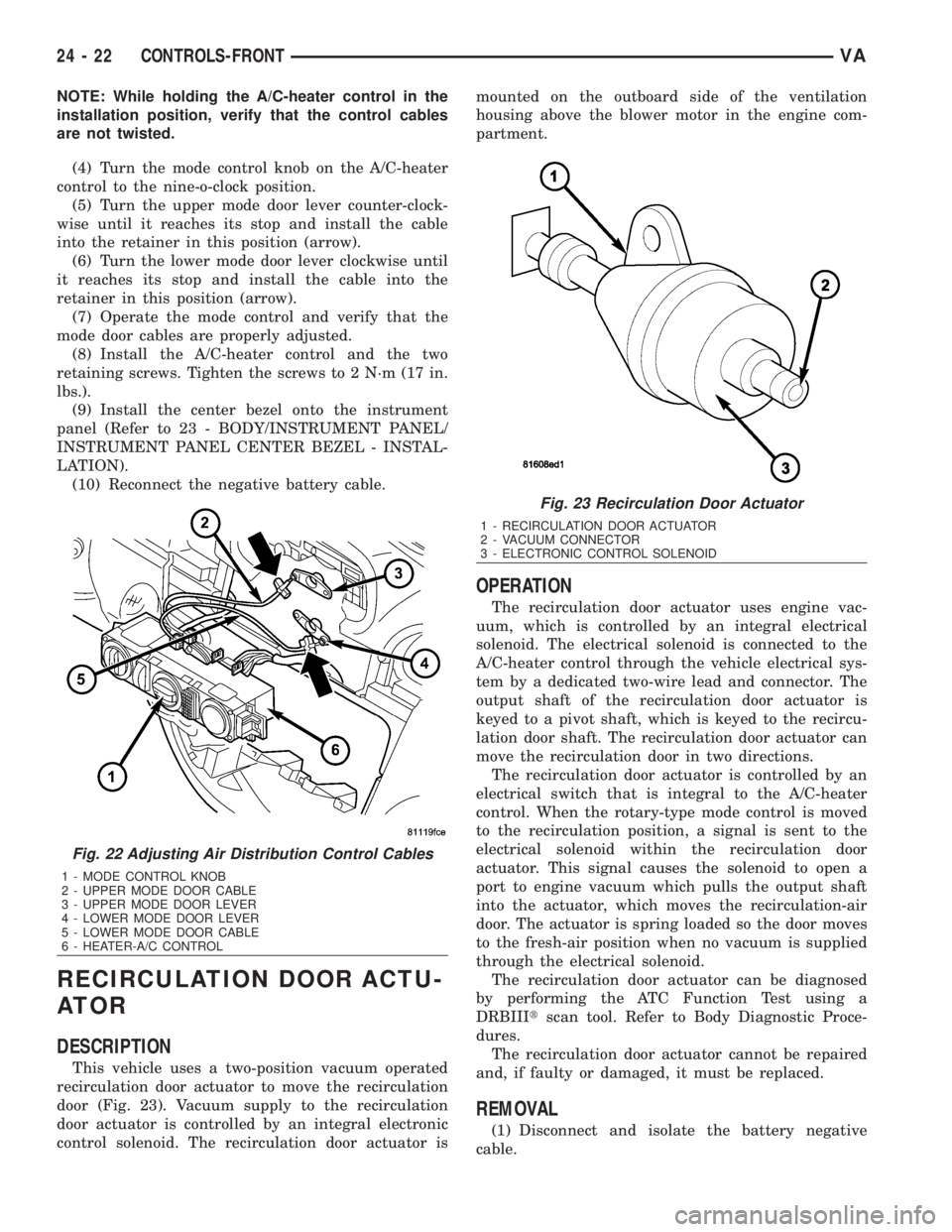
NOTE: While holding the A/C-heater control in the
installation position, verify that the control cables
are not twisted.
(4) Turn the mode control knob on the A/C-heater
control to the nine-o-clock position.
(5) Turn the upper mode door lever counter-clock-
wise until it reaches its stop and install the cable
into the retainer in this position (arrow).
(6) Turn the lower mode door lever clockwise until
it reaches its stop and install the cable into the
retainer in this position (arrow).
(7) Operate the mode control and verify that the
mode door cables are properly adjusted.
(8) Install the A/C-heater control and the two
retaining screws. Tighten the screws to 2 N´m (17 in.
lbs.).
(9) Install the center bezel onto the instrument
panel (Refer to 23 - BODY/INSTRUMENT PANEL/
INSTRUMENT PANEL CENTER BEZEL - INSTAL-
LATION).
(10) Reconnect the negative battery cable.
RECIRCULATION DOOR ACTU-
ATOR
DESCRIPTION
This vehicle uses a two-position vacuum operated
recirculation door actuator to move the recirculation
door (Fig. 23). Vacuum supply to the recirculation
door actuator is controlled by an integral electronic
control solenoid. The recirculation door actuator ismounted on the outboard side of the ventilation
housing above the blower motor in the engine com-
partment.
OPERATION
The recirculation door actuator uses engine vac-
uum, which is controlled by an integral electrical
solenoid. The electrical solenoid is connected to the
A/C-heater control through the vehicle electrical sys-
tem by a dedicated two-wire lead and connector. The
output shaft of the recirculation door actuator is
keyed to a pivot shaft, which is keyed to the recircu-
lation door shaft. The recirculation door actuator can
move the recirculation door in two directions.
The recirculation door actuator is controlled by an
electrical switch that is integral to the A/C-heater
control. When the rotary-type mode control is moved
to the recirculation position, a signal is sent to the
electrical solenoid within the recirculation door
actuator. This signal causes the solenoid to open a
port to engine vacuum which pulls the output shaft
into the actuator, which moves the recirculation-air
door. The actuator is spring loaded so the door moves
to the fresh-air position when no vacuum is supplied
through the electrical solenoid.
The recirculation door actuator can be diagnosed
by performing the ATC Function Test using a
DRBIIItscan tool. Refer to Body Diagnostic Proce-
dures.
The recirculation door actuator cannot be repaired
and, if faulty or damaged, it must be replaced.
REMOVAL
(1) Disconnect and isolate the battery negative
cable.
Fig. 22 Adjusting Air Distribution Control Cables
1 - MODE CONTROL KNOB
2 - UPPER MODE DOOR CABLE
3 - UPPER MODE DOOR LEVER
4 - LOWER MODE DOOR LEVER
5 - LOWER MODE DOOR CABLE
6 - HEATER-A/C CONTROL
Fig. 23 Recirculation Door Actuator
1 - RECIRCULATION DOOR ACTUATOR
2 - VACUUM CONNECTOR
3 - ELECTRONIC CONTROL SOLENOID
24 - 22 CONTROLS-FRONTVA
Page 2147 of 2305
(7) With the DRBIIItscan tool in Cabin Heater,
select System Tests and Dosing Pump Prime. Allow
the dosing pump to run for the full 45 second cycle
time. When the 45 second cycle is complete, press
Page Back on the DRBIIItscan tool key pad to exit
the Dosing Pump Prime. The Dosing Pump Priming
procedure is now complete.
HEATER UNIT
REMOVAL
HEATER UNIT
WARNING: Do not operate the diesel supplemental
cabin heater in an enclosed area such as a garage
that does not have exhaust ventilation facilities.
Always vent the cabin heater exhaust when operat-
ing the cabin heater. Allow the diesel supplemental
cabin heater to cool before performing any service
procedures to the cabin heater. Verify that all diesel
supplemental cabin heater fuel lines are securely
fastened to their respective components before per-
forming any service procedures to the cabin heater.
Failure to follow these warnings may result in pos-
sible personal injury or death.
(1) Raise and support the vehicle. Take note of the
location of the flexible section of the cabin heater
exhaust tube.
(2) Drain the engine cooling system (Refer to 7 -
COOLING - STANDARD PROCEDURE - DRAINING
COOLING SYSTEM).
(3) Carefully open one hose to the underbody tube
assembly and drain the remaining coolant. A salvage
hose is a good idea to control the residual coolant, as
flow will occur from both the cabin heater and the
hose and tube assemblies.
(4) Remove the second hose from the underbody
hose and tube assembly.
(5) Loosen the hose and tube assembly from the
toe-board crossmember at two locations.
(6) Disconnect the electrical connector from the
body harness near the toe-board crossmember and
rail.
(7) Remove the wiring harness from the toe-board
crossmember (Refer to 24 - HEATING & AIR CON-
DITIONING/CABIN HEATER/HEATER UNIT -
REMOVAL - WIRE HARNESS).
(8) Open the fuel filler cap. Disconnect the rubber
fuel hose between the body tube assembly and the
fuel pump nipple at the body tube joint. A minimal
amount of fuel may flow from the open port.
NOTE: Utilize an approved fuel storage container to
catch any residual fuel.(9) Loosen the two fasteners at the rail. Take care
to notice that the exhaust tube bracket tab is on top
of the heater bracket and that there are two spacer
washers installed between the rubber grommets.
(10) Remove the flexible section of the cabin
heater exhaust tube from the exhaust tube by loos-
ening the clamp. Remove the hose from the exhaust
tube. Removal of the rail tube assembly may aid in
this service operation (Refer to 24 - HEATING & AIR
CONDITIONING/CABIN HEATER/EXHAUST TUBE
- REMOVAL).
(11) Remove seat hex nut at the heater mounting
flange to crossmember.
(12) Loosen the remaining fasteners which mount
the exhaust tube assembly to the vehicle.
(a) Install a suitable support device under the
cabin heater and secure the cabin heater to the
support.
(13) Loosen the remaining three fasteners to the
crossmembers.
(14) Remove the loosened fasteners that support
the cabin heater while supporting the weight of the
heater.
(15) Swing the cabin heater mounting bracket
from between the exhaust bracket and rail mounting
location. Drain any residual coolant from the cabin
heater.
(16) Remove the cabin heater from the vehicle.
WIRE HARNESS
(1) Raise and support the vehicle while taking note
of the location of the flexible exhaust tube section.
(2) Disconnect the cabin heater wire harness con-
nector from the vehicle wiring harness.
(3) Disconnect the cabin heater wire harness con-
nector from the dosing pump.
(4) Disconnect the two cabin heater wire harness
connectors from the cabin heater controller.
(5) Remove two wiring harness retainers from the
underbody.
(6) Remove two wiring harness retainers from the
cabin heater shield.
(7) Carefully route the cabin heater wire harness
out the left side between the heater unit and the
heater shield.
INSTALLATION
HEATER UNIT
(1) Install the cabin heater mounting bracket
between the exhaust bracket and the rail mounting
location.
(2) Support the cabin heater and install the fasten-
ers that secure the cabin heater to the mounting
bracket.
(3) Install the three fasteners to the crossmem-
bers. Tighten the M6 fasteners to 7 N´m (62 in. lbs.).
24 - 110 CABIN HEATERVA
Page 2159 of 2305
INSIDE HANDLE ACTUATOR......23-33, 23-36
INSTRUMENT CLUSTER................8J-2
INSTRUMENT PANEL ANTENNA CABLE....8A-2
INSTRUMENT PANEL ASSEMBLY........23-59
INSTRUMENT PANEL CENTER BEZEL.....23-57
INSTRUMENT PANEL DUCTS...........24-51
INTAKE AIR PRESSURE SENSOR........14-43
INTAKE AIR TEMPERATURE SENSOR.....14-42
INTAKE MANIFOLD....................9-65
INTERIOR..........................23-70
INTERMEDIATE SHAFT.................19-4
INTERNATIONAL SYMBOLS...............0-9
INTERNATIONAL SYMBOLS...........Intro.-2
INTRUSION SENSOR...................8Q-1
IN - CAR TEMPERATURE SENSOR.......24-21
JUMP STARTING.......................0-6
KEY / LOCK CYLINDER.................19-5
KNUCKLE.............................2-5
LAMPS / LIGHTING - EXTERIOR..........8L-2
LAMPS / LIGHTING - INTERIOR.........8L-28
LATCH RELEASE CABLE...............23-52
LATCH RELEASE HANDLE..............23-52
LATCH STRIKER.....................23-18
LATCH ..................23-18, 23-33, 23-52
LATCH / LOCK CONTROL...............23-38
LATERAL ACCELERATION SENSOR........5-33
LEFT MOUNT.........................9-55
LEVER..............................5-26
LICENSE PLATE BRACKET..............23-48
LICENSE PLATE LAMP BULB...........8L-19
LICENSE PLATE LAMP UNIT............8L-19
LINKAGE............................19-9
LIQUID LINE........................24-77
LOCK CYLINDER.....................23-18
LOW BEAM HEADLAMP BULB..........8L-20
LOW FUEL INDICATOR................8J-19
LOW OIL LEVEL INDICATOR............8J-20
LOWER BALL JOINT....................2-6
LOWER CONTROL ARM.................2-6
LOWER ROLLER ARM.................23-37
MAINTENANCE INDICATOR.............8J-20
MAINTENANCE SCHEDULES..............0-8
MALFUNCTION INDICATOR LAMP (MIL) . . . 8J-21
MANIFOLD AIR FLOW (MAF) SENSOR....14-44
MASTER CYLINDER...................5-17
MASTER LOCK SWITCH................8N-1
METRIC SYSTEM...................Intro.-6
MODE DOOR CABLES.................24-21
MULTI - FUNCTION INDICATOR..........8J-22
MULTI - FUNCTION SWITCH............8L-21
O2 SENSOR.........................14-45
ODOMETER.........................8J-22
OIL COOLER & LINES..................9-56
OIL FILTER ..........................9-57
OIL JET .............................9-57
OIL PAN .............................9-58
OIL PUMP...........................9-61
OIL PUMP.........................21-154
OIL SENSOR.........................9-64
OIL ................................9-56
OPENING DIMENSIONS................23-93
OUTPUT SHAFT BEARING.............21-156
OUTPUT SHAFT SEAL................21-159
PAINT TOUCH - UP...................23-77
PAINT.............................23-77
PARK BRAKE INDICATOR..............8J-23
PARK BRAKE SWITCH.................8L-21
PARK LOCK CABLE..................21-160
PARKING BRAKE......................5-23
PASSENGER AIRBAG BRACKET.........8O-27
PASSENGER AIRBAG.................8O-24
PASSENGER HEATED SEAT SWITCH.....8G-13
PEDAL..............................5-19
PISTON & CONNECTING ROD............9-45
PISTON RINGS.......................9-52
PISTONS..........................21-163
PLANETARY GEARTRAIN..............21-164
PLUMBING.........................24-61
POWER BRAKE BOOSTER...............5-19
POWER DISTRIBUTION CENTER.......8W-97-3
POWER DISTRIBUTION..............8W-97-1
POWER MIRROR SWITCH..............8N-3
POWER MIRRORS....................8N-3
POWER OUTLET
...................8W-97-3
POWER WINDOW SWITCH
..............8N-5
POWER WINDOWS
....................8N-5
PROP ROD
.........................23-53
PROPELLER SHAFT
.................3-1, 3-7PUMP.............................19-11
QUARTER TRIM PANEL................23-74
QUARTER WINDOW..................23-84
RADIATOR CROSSMEMBER............23-49
RADIATOR FAN.......................7-14
RADIATOR PRESSURE CAP..............7-19
RADIATOR...........................7-17
RADIO..............................8A-2
RAIN SENSOR CONTROL MODULE......8R-15
RAIN SENSOR.......................8R-12
REAR AXLE..........................3-12
REAR A / C CONDENSER FAN...........24-83
REAR A / C EVAPORATOR..............24-84
REAR A / C EXPANSION VALVE..........24-85
REAR BUMPER - STEP.................13-2
REAR CROSSMEMBER - TRANSMISSION . . 13-11
REAR DISCHARGE LINE...............24-88
REAR FASCIA........................13-3
REAR LATCH STRIKER................23-40
REAR LATCH........................23-40
REAR LIQUID LINE...................24-91
REAR RECEIVER / DRIER..............24-94
REAR REFRIGERANT RESERVOIR........24-95
REAR SEAT BACK SHIELD..............23-82
REAR SEAT BELT & RETRACTOR........8O-28
REAR SEAT BELT BUCKLE.............8O-30
REAR SIDE MARKER LAMP BULB.......8L-22
REAR SUCTION LINE..................24-96
REAR TURN LAMP BULB..............8L-23
REAR VIEW MIRROR.................23-75
REAR WHEEL SPEED SENSOR...........5-31
REAR WINDOW DEFOGGER GRID........8G-7
REAR WINDOW DEFOGGER RELAY.......8G-3
REAR WINDOW DEFOGGER SWITCH......8G-4
REAR...............................2-11
RECEIVER / DRIER...................24-79
RECIRCULATION DOOR ACTUATOR......24-22
REFRIGERANT LINE COUPLER..........24-98
REFRIGERANT OIL...................24-81
REFRIGERANT.......................24-80
RELAY...........................8W-97-4
REMOTE KEYLESS ENTRY
TRANSMITTER.......................8N-1
REPEATER LAMP BULB................8L-23
REPEATER LAMP UNIT................8L-24
RESTRAINTS.........................8O-2
RIGHT MOUNT.......................9-56
ROTORS............................5-20
SAFETY LATCH......................23-53
SEAL - PINION........................3-39
SEAT ADJUSTERS - FRONT.............23-81
SEAT BACK CUSHION / COVER - REAR....23-82
SEAT BACK - FRONT..................23-80
SEAT BELT SWITCH..................8O-31
SEAT BELT TENSIONER................8O-32
SEAT BELT TURNING LOOP ADJUSTER . . . 8O-33
SEAT CUSHION - FRONT...............23-80
SEAT CUSHION / COVER - REAR.........23-83
SEATBELT INDICATOR.................8J-24
SEAT - FRONT.......................23-79
SEAT - REAR........................23-81
SECURITY SYSTEM MODULE............8Q-2
SENTRY KEY REMOTE ENTRY MODULE....8Q-2
SERVO..............................8P-2
SHAFT - AXLE DUAL REAR WHEELS......3-27
SHAFT - AXLE SINGLE REAR WHEEL......3-23
SHIFT MECHANISM..................21-168
SHOCK..............................2-13
SHOES..............................5-27
SIDE CURTAIN AIRBAG................8O-35
SIDE IMPACT SENSOR................8O-39
SIDE VIEW MIRROR..................23-49
SIDE VIEW MIRROR - GLASS...........23-50
SIREN..............................8Q-4
SLIDING DOOR......................23-40
SOLENOID.........................21-171
SPARE TIRE CARRIER.................22-12
SPEAKER............................8A-2
SPEED CONTROL.....................8P-1
SPEEDOMETER......................8J-25
SPRING CLAMP PLATES.................2-8
SPRING SHACKLE.....................2-15
SPRING STOP PLATES..................2-9
SPRING
.........................2-7, 2-14
STABILIZER BAR
..................2-9, 2-15
STABILIZER LINK
.................2-10, 2-16
STABILIZER
.........................23-45
STARTER MOTOR RELAY
..............8F-35STARTER MOTOR....................8F-33
STARTING SYSTEM...................8F-28
STEERING ANGLE SENSOR..............5-32
STEERING COLUMN OPENING COVER....23-68
STEERING WHEEL.....................19-6
STEERING...........................19-1
STEPWELL SCUFF PADS...............23-75
STRUT..............................2-10
SUCTION LINE.......................24-81
SUN VISOR.........................23-76
SUPPORT PLATE......................5-23
SUPPRESSOR FILTER - REAR BLOWER
MOTOR............................24-41
SUPPRESSOR FILTER - REAR
CONDENSER FAN....................24-43
SWITCH.............................8P-3
TACHOMETER.......................8J-25
TAIL LAMP UNIT.....................8L-25
TAILPIPE............................11-3
TEMPERATURE CONTROL..............24-38
TEMPERATURE SENSOR...............24-40
TEMPERATURE SENSOR / PARK -
NEUTRAL CONTACT..................21-176
TERMINAL........................Intro.-10
THREADED HOLE REPAIR.............Intro.-6
TIE ROD END ........................19-10
TIME DELAY RELAY....................8L-35
TIMING CHAIN AND SPROCKETS.........9-72
TIMING CHAIN COVER.................9-70
TIMING CHAIN TENSIONER..............9-81
TIRES..............................22-7
TIRES / WHEELS......................22-1
TONE WHEEL........................5-32
TOP COVER.........................23-67
TOP COVER - CLUSTER................23-64
TOP COVER - TRAY...................23-65
TORQUE CONVERTER HUB SEAL.......21-184
TORQUE CONVERTER................21-178
TORQUE REFERENCES...............Intro.-9
TOWING.............................0-7
TRACTION CONTROL INDICATOR........8J-26
TRACTION CONTROL MALFUNCTION
INDICATOR.........................8J-27
TRAILER HITCH......................13-11
TRANSMISSION CONTROL MODULE......8E-6
TRANSPONDER KEY...................8Q-5
TRIM PANEL.............23-18, 23-34, 23-46
TURBOCHARGER SYSTEM..............11-3
TURBOCHARGER......................11-6
TURN SIGNAL INDICATOR..............8J-27
TURN SIGNAL RELAY.................8L-26
UNDERBODY LINES..................24-100
UPPER ROLLER ARM.................23-36
VACUUM PUMP.......................9-54
VALVE COOLER.......................25-6
VALVE SPRINGS......................9-35
VALVE STEM SEALS...................9-34
VALVE ..............................25-5
VEHICLE IDENTIFICATION NUMBER.....Intro.-1
VEHICLE THEFT SECURITY..............8Q-1
VIBRATION DAMPER...................9-53
VOLTAGE REGULATOR.................8F-24
WAIT - TO - START INDICATOR..........8J-28
WASHER FLUID INDICATOR............8J-29
WASHER FLUID LEVEL SWITCH.........8R-16
WASHER HOSES / TUBES..............8R-18
WASHER NOZZLE....................8R-18
WASHER PUMP / MOTOR..............8R-19
WASHER RESERVOIR.................8R-21
WATER IN FUEL SENSOR..............14-30
WATER PUMP........................7-20
WATER VALVE .......................24-83
WATER - IN - FUEL INDICATOR..........8J-29
WHEEL ALIGNMENT...................2-17
WHEELS...........................22-13
WINDOW MOTOR.....................8N-5
WINDOW REGULATOR - MANUAL........23-21
WINDOW REGULATOR - POWER........23-20
WINDSHIELD........................23-85
WIPER ARM........................8R-23
WIPER BLADE.......................8R-26
WIPER LINKAGE.....................8R-28
WIPER MOTOR......................8R-31
WIPER RELAY.......................8R-34
WIPERS/WASHERS....................8R-2
WIRING DIAGRAM INFORMATION......Intro.-1
YAW RATE SENSOR...................5-35
2 INDEXVA
Description Group-Page Description Group-Page Description Group-Page
Page 2166 of 2305
1.0 INTRODUCTION
The procedures contained in this manual include
all of the specifications, instructions, and graphics
needed to diagnose NAG1 Electronic Automatic
Transmission and Shift Lever Assembly problems.
The diagnostics in this manual are based on the
failure condition or symptom being present at the
time of diagnosis.
When repairs are required, refer to the appropri-
ate volume of the service information for the proper
removal and repair procedure.
READ THIS MANUAL BEFORE TRYING TO
DIAGNOSE A VEHICLE TROUBLE CODE.
Diagnostic procedures change every year. New
diagnostic systems may be added and/or carryover
systems may be enhanced. It is recommended that
you review the entire manual to become familiar
with all new and changed diagnostic procedures.
1.1 SYSTEM COVERAGE
This diagnostic procedures manual covers all
Sprinter (VA) equipped with a NAG1 Automatic
Transmission.
1.2 SIX -STEP TROUBLESHOOTING
PROCEDURE
Diagnosis of the NAG1 electronic transmission is
done in six basic steps:
Verification of complaint
Verification of any related symptoms
Symptom analysis
Problem isolation
Repair of isolated problem
Verification of proper operation
2.0 IDENTIFICATION OF
SYSTEM
The NAG1 Transmission family can be identified
by the presence of a 13 pin electrical connector, with
a bayonet lock on the right hand side of the trans-
mission. The connector is oriented horizontally.
3.0 SYSTEM DESCRIPTION AND
FUNCTIONAL OPERATION
3.1 GENERAL DESCRIPTION
The NAG1 electronic transmission is an electron-
ically controlled five speed transmission with a
controlled slip torque converter. The NAG1 elec-tronic transmission is a conventional transmission
in that it uses hydraulically applied clutches to shift
a planetary gear train. However, the electronic
control system replaces many of the mechanical and
hydraulic components used in conventional trans-
mission valve bodies.
The ratios for the gear stages are obtained by 3
planetary gear sets. Fifth Gear is designed as an
Overdrive with a high speed ratio. The gears are
actuated electronically/hydraulically. The electronic
control system enables precise adaptation of pres-
sures to the respective operating conditions and to
the engine output during a shift phase, which
results in a significant improvement in shift qual-
ity.
3.2 FUNCTIONAL OPERATION
The NAG1 electronic transmission has a fully
adaptive control system. The system performs its
functions based on continuous real-time sensor and
switch feedback information. In addition the TCM
receives information from the Shift Lever Assembly,
ECM (engine management) and ABS (chassis sys-
tems) controllers over the CAN bus. The CAN bus is
a high speed communication bus that allows real
time control capability between various controllers.
Most messages are sent every 20 milliseconds, this
means critical information can be shared between
the Transmission, Shifter, Engine and ABS control-
lers. The CAN bus is a two wire bus with aCAN C
Bus (+) circuitand aCAN C Bus (-) circuit. The
CAN bus uses a twisted pair of wires in the harness
to reduce the potential of radio and noise interfer-
ence. The CAN bus also uses a 120 ohm terminating
resistor in both the ECM and Sentry Key Remote
Entry Module (SKREEM) modules. The module
terminating resistance is measured across both
CAN bus circuits at the ECM or SKREEM module.
The control system automatically adapts to
changes in engine performance, vehicle speed, and
transmission temperature variations to provide
consistent shift quality. The control system ensures
that clutch operation during upshifting and down-
shifting is more responsive without increased
harshness. The TCM controls the actuation of sole-
noid valves for modulating shift pressure and gear
change. The required pressure level is calculated
from the load condition, engine speed. Power for the
transmission system is supplied through the Trans-
mission Relay. The TCM is located in the under the
drivers seat of the vehicle.
The Transmission Control Module (TCM) contin-
uously checks for electrical problems, mechanical
problems, and some hydraulic problems. When a
problem is sensed, the TCM stores a diagnostic
trouble code (DTC). Some of these codes cause the
transmission to go into9limp-in9or9default9mode.
1
GENERAL INFORMATION
Page 2167 of 2305
The NAG1 will default in the current gear position
if a DTC is detected, then after a key cycle or shift
to park the transmission will go into Limp-in, which
is mechanical 2nd gear. Some DTC's may allow the
transmission to resume normal operation (recover)
if the detected problem goes away. Permanent
limp-in DTC will recover when the key is cycled, but
if the same DTC is detected for three key cycles the
system will not recover and the DTC must be
cleared from the TCM with the DRBIII scan tool.
Once the DRBIIItis in the Transmission portion
of the diagnostic program, it constantly monitors
the TCM to see if the system is in limp-in mode. If
the transmission is in limp-in mode, the DRBIIIt
will flash the red LED.
3.2.1 CONTROLLER MODES OF
OPERATION
Permanent limp-in mode
When the TCM determines there is a non-
recoverable condition present that will not allow
proper transmission operation, it will place the
transmission in permanent limp-in mode. When the
condition occurs the TCM will turn off all solenoids
as well as the solenoid supply output circuit. If this
occurs while the vehicle is moving, the transmission
will remain in the current gear until the ignition is
turned off or shifter is placed in the9P9position.
Once the shifter has been placed in9P9the Trans-
mission will only allow 2nd gear operation. If the
problem occurs while the vehicle is not moving the
transmission will only allow 2nd gear operation.
Temporary limp-in mode
This mode is the same as the permanent limp-in
mode except if the condition is no longer present the
system will resume normal operation. (Recoverable
DTC)
Undervoltage limp-in mode
When the TCM detects that system voltage has
dropped below 8.5 volts it will disable voltage de-
pendant diagnostics and place the transmission in
the temporary limp-in mode. When the TCM senses
that the voltage has risen above 9.0 volts, normal
transmission operation will be resumed.
Hardware Error Mode
When the TCM detects a major internal error the
transmission will be placed in the permanent
limp-in mode and cease all communication over the
CAN bus. Once the TCM has entered this mode
normal transmission operation will not resume un-
til all DTC's are cleared from the TCM.
Loss of Drive
If the TCM detects a situation that has resulted or
may result in engine or transmission failure, the
transmission will be placed in the neutral position.Improper Ratio, Input Sensor Overspeed, or Engine
Overspeed DTC's will cause the loss of drive.
Controlled Limp-in Mode
When a failure condition does not require the TCM
to shut down the solenoid supply, but the failure is
of a degree where the TCM will place the transmis-
sion into a predefined gear, there will be several
shift performance issues. Examples of this are, with
the transmission slipping the controller will at-
tempt to place the transmission into third gear and
maintain third gear for all forward drive conditions.
Another example is some of the CAN bus message
issues if the TCM does not receive required infor-
mation from the Engine Controller, then default
values are used which may result in poor transmis-
sion shift performance.
3.2.2 MIL ILLUMINATION
For failures detected by the Transmission Con-
troller that result in the controller placing the
transmission into a limp-in mode, except for System
Overvoltage and System Undervoltage DTCs, the
MIL will be illuminated. The Transmission Control
Module will inform the ECM over the CAN bus that
a failure has occurred. The ECM will illuminate the
MIL. If the condition is removed and the failure
becomes Stored (Intermittent), the Transmission
controller will stop reporting that the DTC is active
and the ECM will extinguish the MIL.
NOTE: The MIL will light when the problem is
first detected and it will not go off until the
next ignition cycle, after all problem
conditions have been checked for their
presence. This normally takes several
minutes of driving.
3.2.3 SOLENOIDS
1-2/4-5 solenoid -The 1-2/4-5 solenoid is activated
when the TCM determines that the transmission
must shift into or out of 2nd gear or 5th gear. The
solenoid is only activated during the shifting of the
transmission. When the solenoid is activated, hy-
draulic pressure is applied to the proper shift ele-
ments in the transmission to allow the desired shift.
Once the shift is completed, the solenoid is turned
off.
2-3 solenoid -The 2-3 solenoid is activated when
the TCM determines that the transmission must
shift into or out of 3rd gear. The solenoid is only
activated during the shifting of the transmission.
When the solenoid is activated hydraulic pressure
is applied to the proper shift elements in the trans-
mission to allow the desired shift. Once the shift is
completed, the solenoid is turned off.
2
GENERAL INFORMATION
Page 2168 of 2305
3-4 solenoid -The 3-4 solenoid is activated when
the TCM determines that the transmission must
shift into or out of 4th gear. The solenoid is only
activated during the shifting of the transmission.
When the solenoid is activated, hydraulic pressure
is applied to the proper shift elements in the trans-
mission to allow the desired shift. Once the shift is
completed, the solenoid is turned off.
TCC solenoid -The TCC solenoid is activated
when the TCM determines that the Torque con-
verter clutch should be activated. The TCC clutch is
a variable slip torque clutch that allows control of
torque converter slip from 5% to 95.5% of full TCC
engagement. The clutch is controlled by the TCC
solenoid which is pulse width modulated (PWM) to
provide the desired amount of slip.
Shift Pressure Solenoid -The Shift Pressure
Solenoid is activated when the TCM determines
that a transmission shift is required. The solenoid
is PWM controller to allow the proper amount of
hydraulic pressure to the shift elements. The sole-
noid is only activated during the shifting of the
transmission. When the solenoid is activated, hy-
draulic pressure is removed from the proper shift
elements to allow the desired shift. Once the shift is
completed, the solenoid is turned off.
Modulation pressure solenoid -The modulation
pressure is always active. The solenoid is pulse
width modulated (PWM) controlled and is used to
modulate the hydraulic system pressure to the
desired pressure.
3.2.4 TRANSMISSION COMPONENT
DESCRIPTIONS
Shift Assembly
The Shift Lever Selector transmits all selector lever
positions, as well as selected shift ranges to the
TCM over the CAN Bus. At the same time, the
selector lever positions P, R, N, and D are transmit-
ted by a cable to the selector lever shaft in the
transmission.
Brake shift inter-lock
To prevent unauthorized shifting out of the park
position, the Selector lever is locked in the Park
position until the ignition key is turned to the run
position and the brake pedal is pressed. This will
allow the driver to shift out of the park position.
Reverse Lamp Output
The Reverse Light Switch is integrated into the
shifter module and controls the reverse lights.
Reverse Inhibitor
The Shift Lever Assembly constantly monitors ABS
wheel speed to prevents an inadvertent selection of
reverse at speeds above approximately 6.4 Km/h(4MPH). The Reverse inhibitor is part of the Shift
Lever Assembly and is controlled by the Shift Lever
Assembly module.
Trans temp sensor - P/N Switch circuit
The TCM will detect the selector lever in park and
neutral positions. The TCM does this by monitoring
the Transmission temperature sensor signal along
with the shifter position signals. The P/N switch
contact is operated by a cam located in the trans-
mission which, opens a reed contact switch that is
wired in series with the transmission temperature
sensor. When the P/N contact switch is opened in
park and neutral, the TCM senses a high transmis-
sion temperature. Confirming the P/N switch sta-
tus. Note: In park or neutral, the TCM uses engine
temperature (to avoid setting a DTC). The TCM
sends a hardwired signal to the ECM that will allow
the ECM controlled start circuit to engage in P or N
only. The TCM also sends a P/N bus message to the
ECM to confirm the P/N switch status.
The Normal Transmission Temperature Sensor
resistance is between 500.0 and 2500.0 ohms.
The normal voltage limits for the transmis-
sion temperature sensor, are between 0.5 and
3.0 volts.
Input Speed Sensors
The NAG1 transmission has two input speed sen-
sors N2 and N3, both speed sensors are located on
the valve body and report DTC's for the input speed
sensors errors. The speed sensors are Hall Effect
speed sensors that are used by the TCM to calculate
the transmissions input speed. Since the input
speed could not be measured directly, two of the
drive elements are measured. Two input speed
sensors were required because both drive elements
are not active in all gears. The input sensors N2 and
N3 will report the same input speed in gears 2nd,
3rd or 4th. If the N2 and N3 input speed signals are
not the same in these gears then there is an issue
with the transmission and the DTC Input Sensors
Mismatch will be set.
The N3 input speed is not reported in1st and 5th
gears. The N2 sensor is not reported in Reverse.
The Input Speed Sensor Overspeed is a rationality
check that is intended to indicate a major transmis-
sion failure and will cause a loss of drive (place the
transmission in Neutral)
Output Speed Sensor (ABS signal)
The NAG1 transmission does not have an output
shaft speed sensor. The TCM uses the ABS (An-
tilock Brake System) Wheel Speed sensor informa-
tion, it receives over the CAN bus, to calculate the
transmissions output shaft speed. The TCM moni-
tors the ABS system for functionality and reports
ABS speed sensor and communication DTCs, which
will affect proper transmission operation.
3
GENERAL INFORMATION