2006 MERCEDES-BENZ SPRINTER key
[x] Cancel search: keyPage 1488 of 2305
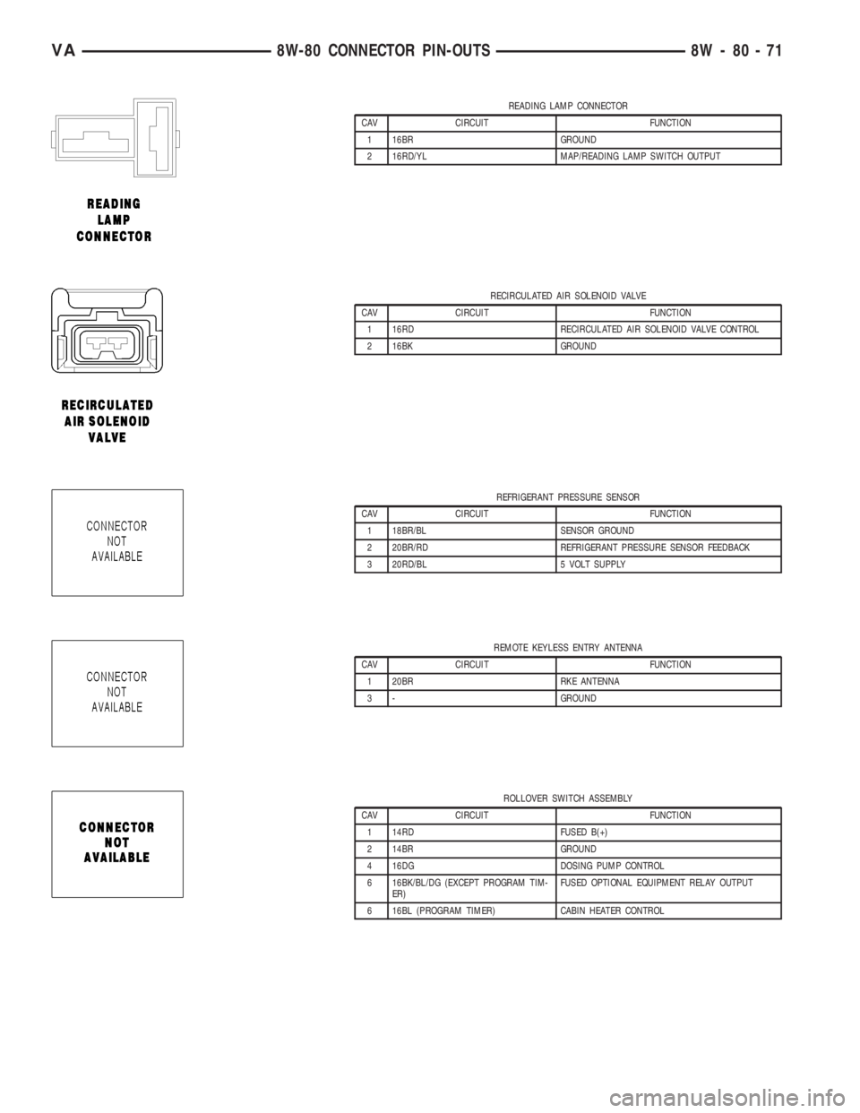
READING LAMP CONNECTOR
CAV CIRCUIT FUNCTION
1 16BR GROUND
2 16RD/YL MAP/READING LAMP SWITCH OUTPUT
RECIRCULATED AIR SOLENOID VALVE
CAV CIRCUIT FUNCTION
1 16RD RECIRCULATED AIR SOLENOID VALVE CONTROL
2 16BK GROUND
REFRIGERANT PRESSURE SENSOR
CAV CIRCUIT FUNCTION
1 18BR/BL SENSOR GROUND
2 20BR/RD REFRIGERANT PRESSURE SENSOR FEEDBACK
3 20RD/BL 5 VOLT SUPPLY
REMOTE KEYLESS ENTRY ANTENNA
CAV CIRCUIT FUNCTION
1 20BR RKE ANTENNA
3 - GROUND
ROLLOVER SWITCH ASSEMBLY
CAV CIRCUIT FUNCTION
1 14RD FUSED B(+)
2 14BR GROUND
4 16DG DOSING PUMP CONTROL
6 16BK/BL/DG (EXCEPT PROGRAM TIM-
ER)FUSED OPTIONAL EQUIPMENT RELAY OUTPUT
6 16BL (PROGRAM TIMER) CABIN HEATER CONTROL
VA8W-80 CONNECTOR PIN-OUTS 8W - 80 - 71
Page 1493 of 2305
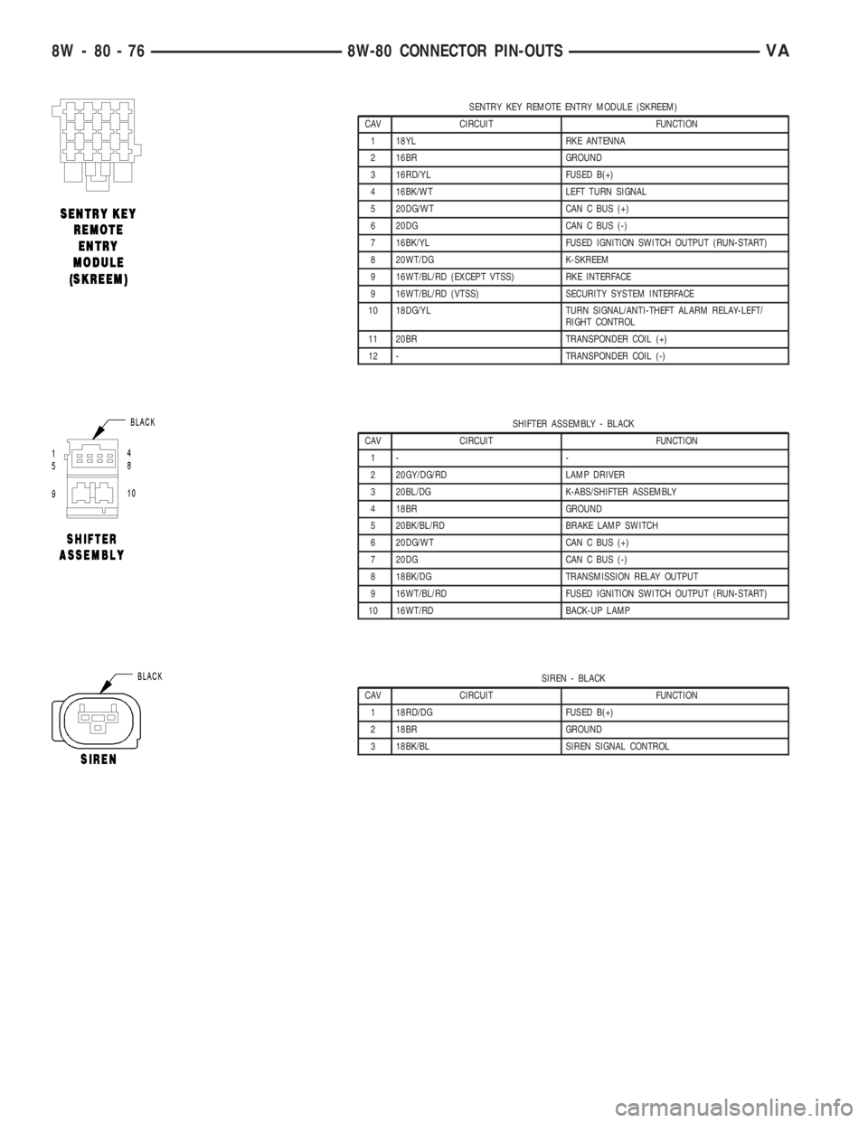
SENTRY KEY REMOTE ENTRY MODULE (SKREEM)
CAV CIRCUIT FUNCTION
1 18YL RKE ANTENNA
2 16BR GROUND
3 16RD/YL FUSED B(+)
4 16BK/WT LEFT TURN SIGNAL
5 20DG/WT CAN C BUS (+)
6 20DG CAN C BUS (-)
7 16BK/YL FUSED IGNITION SWITCH OUTPUT (RUN-START)
8 20WT/DG K-SKREEM
9 16WT/BL/RD (EXCEPT VTSS) RKE INTERFACE
9 16WT/BL/RD (VTSS) SECURITY SYSTEM INTERFACE
10 18DG/YL TURN SIGNAL/ANTI-THEFT ALARM RELAY-LEFT/
RIGHT CONTROL
11 20BR TRANSPONDER COIL (+)
12 - TRANSPONDER COIL (-)
SHIFTER ASSEMBLY - BLACK
CAV CIRCUIT FUNCTION
1- -
2 20GY/DG/RD LAMP DRIVER
3 20BL/DG K-ABS/SHIFTER ASSEMBLY
4 18BR GROUND
5 20BK/BL/RD BRAKE LAMP SWITCH
6 20DG/WT CAN C BUS (+)
7 20DG CAN C BUS (-)
8 18BK/DG TRANSMISSION RELAY OUTPUT
9 16WT/BL/RD FUSED IGNITION SWITCH OUTPUT (RUN-START)
10 16WT/RD BACK-UP LAMP
SIREN - BLACK
CAV CIRCUIT FUNCTION
1 18RD/DG FUSED B(+)
2 18BR GROUND
3 18BK/BL SIREN SIGNAL CONTROL
8W - 80 - 76 8W-80 CONNECTOR PIN-OUTSVA
Page 1511 of 2305
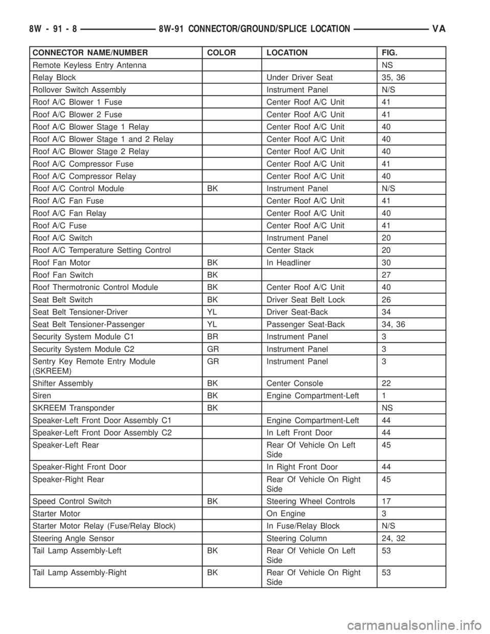
CONNECTOR NAME/NUMBER COLOR LOCATION FIG.
Remote Keyless Entry Antenna NS
Relay Block Under Driver Seat 35, 36
Rollover Switch Assembly Instrument Panel N/S
Roof A/C Blower 1 Fuse Center Roof A/C Unit 41
Roof A/C Blower 2 Fuse Center Roof A/C Unit 41
Roof A/C Blower Stage 1 Relay Center Roof A/C Unit 40
Roof A/C Blower Stage 1 and 2 Relay Center Roof A/C Unit 40
Roof A/C Blower Stage 2 Relay Center Roof A/C Unit 40
Roof A/C Compressor Fuse Center Roof A/C Unit 41
Roof A/C Compressor Relay Center Roof A/C Unit 40
Roof A/C Control Module BK Instrument Panel N/S
Roof A/C Fan Fuse Center Roof A/C Unit 41
Roof A/C Fan Relay Center Roof A/C Unit 40
Roof A/C Fuse Center Roof A/C Unit 41
Roof A/C Switch Instrument Panel 20
Roof A/C Temperature Setting Control Center Stack 20
Roof Fan Motor BK In Headliner 30
Roof Fan Switch BK 27
Roof Thermotronic Control Module BK Center Roof A/C Unit 40
Seat Belt Switch BK Driver Seat Belt Lock 26
Seat Belt Tensioner-Driver YL Driver Seat-Back 34
Seat Belt Tensioner-Passenger YL Passenger Seat-Back 34, 36
Security System Module C1 BR Instrument Panel 3
Security System Module C2 GR Instrument Panel 3
Sentry Key Remote Entry Module
(SKREEM)GR Instrument Panel 3
Shifter Assembly BK Center Console 22
Siren BK Engine Compartment-Left 1
SKREEM Transponder BK NS
Speaker-Left Front Door Assembly C1 Engine Compartment-Left 44
Speaker-Left Front Door Assembly C2 In Left Front Door 44
Speaker-Left Rear Rear Of Vehicle On Left
Side45
Speaker-Right Front Door In Right Front Door 44
Speaker-Right Rear Rear Of Vehicle On Right
Side45
Speed Control Switch BK Steering Wheel Controls 17
Starter Motor On Engine 3
Starter Motor Relay (Fuse/Relay Block) In Fuse/Relay Block N/S
Steering Angle Sensor Steering Column 24, 32
Tail Lamp Assembly-Left BK Rear Of Vehicle On Left
Side53
Tail Lamp Assembly-Right BK Rear Of Vehicle On Right
Side53
8W - 91 - 8 8W-91 CONNECTOR/GROUND/SPLICE LOCATIONVA
Page 1514 of 2305
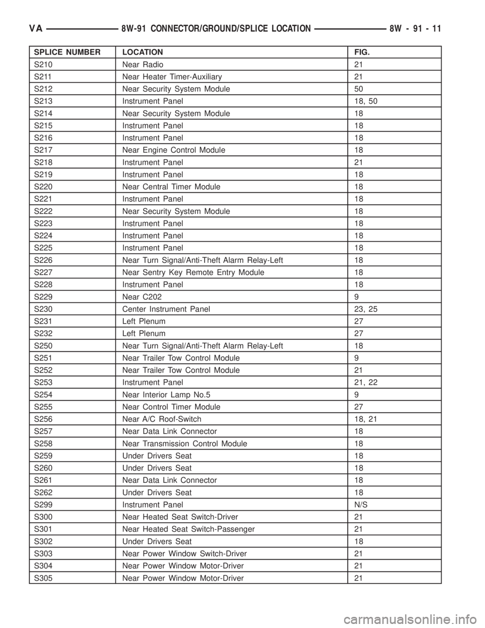
SPLICE NUMBER LOCATION FIG.
S210 Near Radio 21
S211 Near Heater Timer-Auxiliary 21
S212 Near Security System Module 50
S213 Instrument Panel 18, 50
S214 Near Security System Module 18
S215 Instrument Panel 18
S216 Instrument Panel 18
S217 Near Engine Control Module 18
S218 Instrument Panel 21
S219 Instrument Panel 18
S220 Near Central Timer Module 18
S221 Instrument Panel 18
S222 Near Security System Module 18
S223 Instrument Panel 18
S224 Instrument Panel 18
S225 Instrument Panel 18
S226 Near Turn Signal/Anti-Theft Alarm Relay-Left 18
S227 Near Sentry Key Remote Entry Module 18
S228 Instrument Panel 18
S229 Near C202 9
S230 Center Instrument Panel 23, 25
S231 Left Plenum 27
S232 Left Plenum 27
S250 Near Turn Signal/Anti-Theft Alarm Relay-Left 18
S251 Near Trailer Tow Control Module 9
S252 Near Trailer Tow Control Module 21
S253 Instrument Panel 21, 22
S254 Near Interior Lamp No.5 9
S255 Near Control Timer Module 27
S256 Near A/C Roof-Switch 18, 21
S257 Near Data Link Connector 18
S258 Near Transmission Control Module 18
S259 Under Drivers Seat 18
S260 Under Drivers Seat 18
S261 Near Data Link Connector 18
S262 Under Drivers Seat 18
S299 Instrument Panel N/S
S300 Near Heated Seat Switch-Driver 21
S301 Near Heated Seat Switch-Passenger 21
S302 Under Drivers Seat 18
S303 Near Power Window Switch-Driver 21
S304 Near Power Window Motor-Driver 21
S305 Near Power Window Motor-Driver 21
VA8W-91 CONNECTOR/GROUND/SPLICE LOCATION 8W - 91 - 11
Page 1629 of 2305
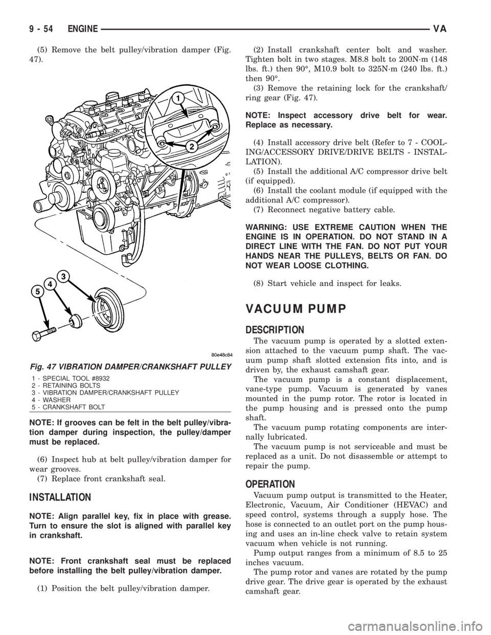
(5) Remove the belt pulley/vibration damper (Fig.
47).
NOTE: If grooves can be felt in the belt pulley/vibra-
tion damper during inspection, the pulley/damper
must be replaced.
(6) Inspect hub at belt pulley/vibration damper for
wear grooves.
(7) Replace front crankshaft seal.
INSTALLATION
NOTE: Align parallel key, fix in place with grease.
Turn to ensure the slot is aligned with parallel key
in crankshaft.
NOTE: Front crankshaft seal must be replaced
before installing the belt pulley/vibration damper.
(1) Position the belt pulley/vibration damper.(2) Install crankshaft center bolt and washer.
Tighten bolt in two stages. M8.8 bolt to 200N´m (148
lbs. ft.) then 90É, M10.9 bolt to 325N´m (240 lbs. ft.)
then 90É.
(3) Remove the retaining lock for the crankshaft/
ring gear (Fig. 47).
NOTE: Inspect accessory drive belt for wear.
Replace as necessary.
(4) Install accessory drive belt (Refer to 7 - COOL-
ING/ACCESSORY DRIVE/DRIVE BELTS - INSTAL-
LATION).
(5) Install the additional A/C compressor drive belt
(if equipped).
(6) Install the coolant module (if equipped with the
additional A/C compressor).
(7) Reconnect negative battery cable.
WARNING: USE EXTREME CAUTION WHEN THE
ENGINE IS IN OPERATION. DO NOT STAND IN A
DIRECT LINE WITH THE FAN. DO NOT PUT YOUR
HANDS NEAR THE PULLEYS, BELTS OR FAN. DO
NOT WEAR LOOSE CLOTHING.
(8) Start vehicle and inspect for leaks.
VACUUM PUMP
DESCRIPTION
The vacuum pump is operated by a slotted exten-
sion attached to the vacuum pump shaft. The vac-
uum pump shaft slotted extension fits into, and is
driven by, the exhaust camshaft gear.
The vacuum pump is a constant displacement,
vane-type pump. Vacuum is generated by vanes
mounted in the pump rotor. The rotor is located in
the pump housing and is pressed onto the pump
shaft.
The vacuum pump rotating components are inter-
nally lubricated.
The vacuum pump is not serviceable and must be
replaced as a unit. Do not disassemble or attempt to
repair the pump.
OPERATION
Vacuum pump output is transmitted to the Heater,
Electronic, Vacuum, Air Conditioner (HEVAC) and
speed control, systems through a supply hose. The
hose is connected to an outlet port on the pump hous-
ing and uses an in-line check valve to retain system
vacuum when vehicle is not running.
Pump output ranges from a minimum of 8.5 to 25
inches vacuum.
The pump rotor and vanes are rotated by the pump
drive gear. The drive gear is operated by the exhaust
camshaft gear.
Fig. 47 VIBRATION DAMPER/CRANKSHAFT PULLEY
1 - SPECIAL TOOL #8932
2 - RETAINING BOLTS
3 - VIBRATION DAMPER/CRANKSHAFT PULLEY
4 - WASHER
5 - CRANKSHAFT BOLT
9 - 54 ENGINEVA
Page 1684 of 2305
(7) Connect a scan tool, select from Main Menu,
System Select, Engine, System Tests, Fuel Quantity
Test, Engine Cranking Test and follow the screen.
(8) After ten seconds, a maximum of 2.5 ml
(between2&3graduation lines) may be reached in
the inner vials. If the level has exceeded the 2.5 ml,
replace that affected cylinder's injector, clear the
memory using the scan tool, empty the test vials, and
retest.
RUNNING TEST
NOTE: If an injector is found to be out of specifica-
tion, repeat this test procedure after the injector
replacement. Hydraulic flow will take the path of
least resistance and multiple failures may be identi-
fied. Engine temperature must be above 80É C
(176ÉF) to perform the running test.
Perform this test with the engine at operating tem-
perature. This test will assist in determining a defec-
tive or internally leaking injector(s) is present by
measuring the amount of fuel return.
(1) Turn the ignition off.
(2) Remove the engine cover (Refer to 9 - ENGINE
- REMOVAL).
(3) Disconnect the fuel return hoses at the top of
the injectors.
(4) Pinch off the fuel return line at the banjo bolt
fitting of the fuel rail.
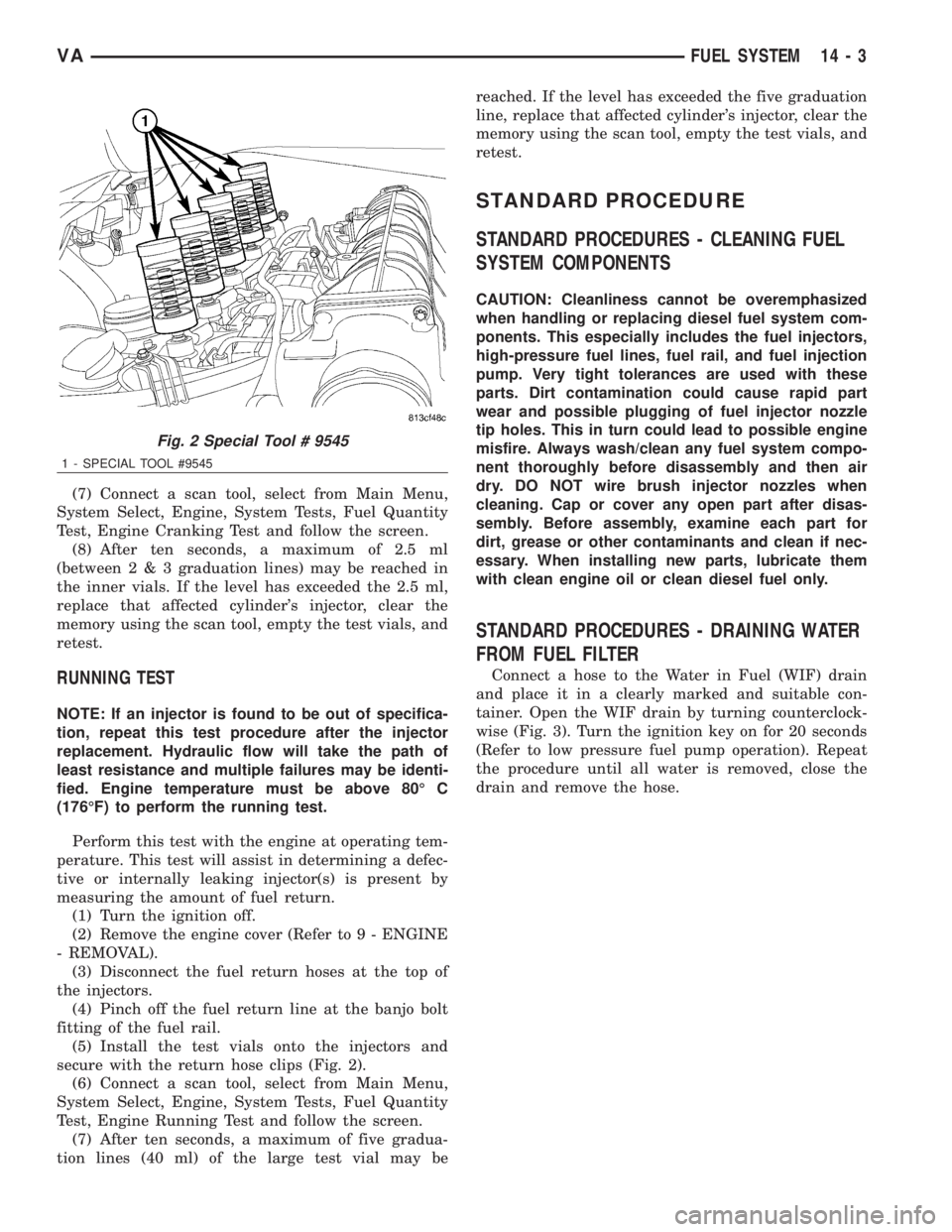
(5) Install the test vials onto the injectors and
secure with the return hose clips (Fig. 2).
(6) Connect a scan tool, select from Main Menu,
System Select, Engine, System Tests, Fuel Quantity
Test, Engine Running Test and follow the screen.
(7) After ten seconds, a maximum of five gradua-
tion lines (40 ml) of the large test vial may bereached. If the level has exceeded the five graduation
line, replace that affected cylinder's injector, clear the
memory using the scan tool, empty the test vials, and
retest.
STANDARD PROCEDURE
STANDARD PROCEDURES - CLEANING FUEL
SYSTEM COMPONENTS
CAUTION: Cleanliness cannot be overemphasized
when handling or replacing diesel fuel system com-
ponents. This especially includes the fuel injectors,
high-pressure fuel lines, fuel rail, and fuel injection
pump. Very tight tolerances are used with these
parts. Dirt contamination could cause rapid part
wear and possible plugging of fuel injector nozzle
tip holes. This in turn could lead to possible engine
misfire. Always wash/clean any fuel system compo-
nent thoroughly before disassembly and then air
dry. DO NOT wire brush injector nozzles when
cleaning. Cap or cover any open part after disas-
sembly. Before assembly, examine each part for
dirt, grease or other contaminants and clean if nec-
essary. When installing new parts, lubricate them
with clean engine oil or clean diesel fuel only.
STANDARD PROCEDURES - DRAINING WATER
FROM FUEL FILTER
Connect a hose to the Water in Fuel (WIF) drain
and place it in a clearly marked and suitable con-
tainer. Open the WIF drain by turning counterclock-
wise (Fig. 3). Turn the ignition key on for 20 seconds
(Refer to low pressure fuel pump operation). Repeat
the procedure until all water is removed, close the
drain and remove the hose.
Fig. 2 Special Tool # 9545
1 - SPECIAL TOOL #9545
VAFUEL SYSTEM 14 - 3
Page 1733 of 2305
COLUMN
TABLE OF CONTENTS
page page
COLUMN
SPECIFICATIONS - TORQUE CHART.........4
INTERMEDIATE SHAFT
REMOVAL.............................4
INSTALLATION..........................5
KEY/LOCK CYLINDER
REMOVAL.............................5INSTALLATION..........................6
STEERING WHEEL
REMOVAL.............................6
INSTALLATION..........................6
COLUMN
SPECIFICATIONS - TORQUE CHART
TORQUE SPECIFICATIONS
DESCRIPTION N´m Ft. Lbs. In. Lbs.
Steering Wheel With Air-
bag To Steering Shaft80 59 Ð
Jacket Tube For Steering
Shaft To Waist Rail25 18 221
U-Joint To Steering Gear
Shaft24 18 212
INTERMEDIATE SHAFT
REMOVAL
(1) Disconnect the ground cable from the battery.
(2) Remove the air bag module from the steering
wheel.
(3) Turn the steering wheel and lock the steering
wheel in the straight ahead position.The position
of the steering gear must not be altered again
for the entire duration of the work procedure.
(4) Remove the electrical center.
(5) Remove the steering wheel bolt.
(6) Remove the steering wheel from the steering
column.
(7) Remove the clockspring.Unscrew the retain-
ing bolts just enough to be able to remove the
clockspring. Do not twist or disassemble the
clockspring.
(8) Remove the combination switch.
(9) Disconnect the electrical connector for the igni-
tion lock.
(10) Remove the spring for the brake pedal from
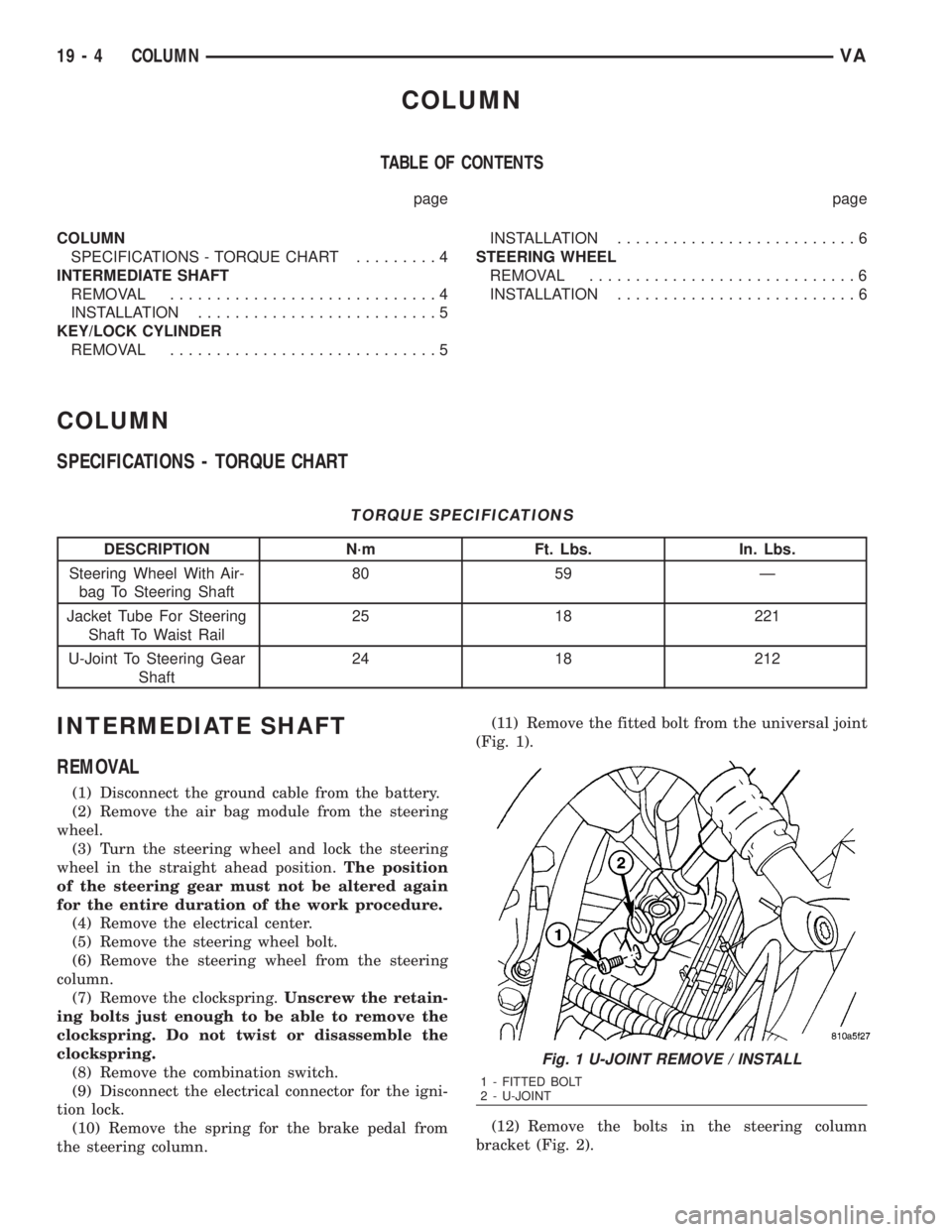
the steering column.(11) Remove the fitted bolt from the universal joint
(Fig. 1).
(12) Remove the bolts in the steering column
bracket (Fig. 2).
Fig. 1 U-JOINT REMOVE / INSTALL
1 - FITTED BOLT
2 - U-JOINT
19 - 4 COLUMNVA
Page 1734 of 2305
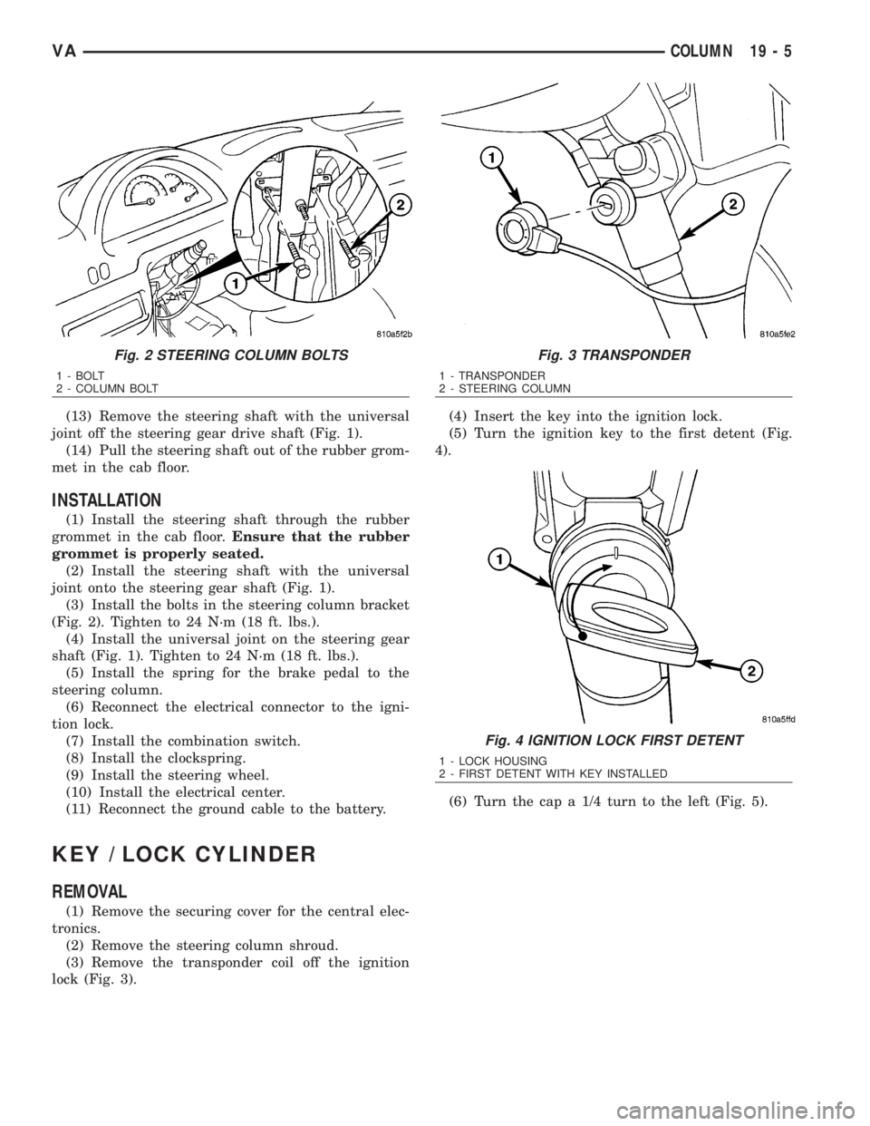
(13) Remove the steering shaft with the universal
joint off the steering gear drive shaft (Fig. 1).
(14) Pull the steering shaft out of the rubber grom-
met in the cab floor.
INSTALLATION
(1) Install the steering shaft through the rubber
grommet in the cab floor.Ensure that the rubber
grommet is properly seated.
(2) Install the steering shaft with the universal
joint onto the steering gear shaft (Fig. 1).
(3) Install the bolts in the steering column bracket
(Fig. 2). Tighten to 24 N´m (18 ft. lbs.).
(4) Install the universal joint on the steering gear
shaft (Fig. 1). Tighten to 24 N´m (18 ft. lbs.).
(5) Install the spring for the brake pedal to the
steering column.
(6) Reconnect the electrical connector to the igni-
tion lock.
(7) Install the combination switch.
(8) Install the clockspring.
(9) Install the steering wheel.
(10) Install the electrical center.
(11) Reconnect the ground cable to the battery.
KEY / LOCK CYLINDER
REMOVAL
(1) Remove the securing cover for the central elec-
tronics.
(2) Remove the steering column shroud.
(3) Remove the transponder coil off the ignition
lock (Fig. 3).(4) Insert the key into the ignition lock.
(5) Turn the ignition key to the first detent (Fig.
4).
(6) Turn the cap a 1/4 turn to the left (Fig. 5).
Fig. 2 STEERING COLUMN BOLTS
1 - BOLT
2 - COLUMN BOLT
Fig. 3 TRANSPONDER
1 - TRANSPONDER
2 - STEERING COLUMN
Fig. 4 IGNITION LOCK FIRST DETENT
1 - LOCK HOUSING
2 - FIRST DETENT WITH KEY INSTALLED
VACOLUMN 19 - 5