2006 MERCEDES-BENZ SPRINTER key
[x] Cancel search: keyPage 986 of 2305
POWER SYSTEMS
TABLE OF CONTENTS
page page
POWER LOCKS............................ 1
POWER MIRRORS......................... 3POWER WINDOWS......................... 5
POWER LOCKS
TABLE OF CONTENTS
page page
DOOR LOCK MOTOR
REMOVAL.............................1
INSTALLATION..........................1
REMOTE KEYLESS ENTRY TRANSMITTER
DESCRIPTION..........................1
MASTER LOCK SWITCH
DESCRIPTION..........................1DIAGNOSIS AND TESTING - MASTER LOCK
SWITCH.............................1
REMOVAL.............................2
INSTALLATION..........................2
DOOR LOCK MOTOR
REMOVAL
(1) Disconnect and isolate the battery negative
cable.
(2) Remove the door trim panel.
(3) Remove the door lock.
(4) Remove the door lock motor from the door lock.
INSTALLATION
(1) Install the door lock motor to the door lock.
(2) Install the door lock.
(3) Install the door trim panel.
(4) Connect the battery negative cable.
REMOTE KEYLESS ENTRY
TRANSMITTER
DESCRIPTION
Pressing the unlock button on the transmitter will
unlock the drivers door, pressing it a second time
within 2.5 seconds will unlock all other doors. The
transmitter has a range of 10 meters. A key is inte-
gral to the transmitter.
When a transmitter is lost, it is necessary to dis-
able the affected transmitter so that it can no longer
be used to operate the vehicle. It will then be neces-
sary to program a new transmitter to the vehicle.
MASTER LOCK SWITCH
DESCRIPTION
The master lock switch is a momentary contact
switch. Pressing the once in the up direction unlocks
the driver door. Pressing it again in the same direc-
tion unlocks all doors. Pressing the button in the
down direction locks all doors.
DIAGNOSIS AND TESTING - MASTER LOCK
SWITCH
(1) Disconnect and isolate the battery negative
cable.
(2) Remove the switch to be tested.
(3) Using an ohmmeter, test switch for continuity
(Fig. 1).
(4) If test results are not obtained as shown in the
test table, replace the switch.
VAPOWER SYSTEMS 8N - 1
Page 1004 of 2305
side of the rotor hub also serves as an integral
molded plastic turn signal cancel cam.
A single connector receptacle on the upper surface
of the rotor has pigtail wires that connect to the horn
switch and the driver airbag on the steering wheel,
while a single connector receptacle on the lower sur-
face of the case has pigtail wires that connect the
clockspring to the vehicle wire harness on the steer-
ing column. Within the plastic case and wound
around the rotor spool is a long ribbon-like tape that
consists of several thin copper wire leads sandwiched
between two thin plastic membranes. The outer end
of the tape terminates at the connector receptacle
that faces the steering column, while the inner end of
the tape terminates at the connector receptacle on
the hub of the clockspring rotor that faces the steer-
ing wheel.
Service replacement clocksprings are shipped pre-
centered and with the mounting screws backed out
from the case far enough to engage the access holes
in the upper surface of the rotor. The mounting
screws secure the centered clockspring rotor to the
clockspring case during shipment, but allow free
rotation of the rotor once the clockspring is properly
installed on the steering column. (Refer to 8 - ELEC-
TRICAL/RESTRAINTS/CLOCKSPRING - STAN-
DARD PROCEDURE - CLOCKSPRING
CENTERING).
The clockspring cannot be repaired. If the clock-
spring is faulty, damaged, or if the driver airbag has
been deployed, the clockspring must be replaced.
OPERATION
The clockspring is a mechanical electrical circuit
component that is used to provide continuous electri-
cal continuity between the fixed vehicle wire harness
and the electrical components mounted on or in the
rotating steering wheel. On this model the rotating
electrical components include the driver airbag and
the horn switch. The clockspring case is positioned
and secured to the multi-function switch housing
near the top of the steering column. The connector
receptacle on the underside of the fixed clockspring
case connects the clockspring to the vehicle electrical
system through two take outs with connectors from
the vehicle wire harness.
The clockspring rotor is movable and is keyed by
integral molded ribs on the inner circumference of
the rotor hub to the splines on the external circum-
ference of the upper steering column shaft. The two
integral lobes of the turn signal cancel cam formation
on the lower surface of the clockspring rotor hub con-
tact the turn signal cancel actuator of the multi-func-
tion switch to provide automatic turn signal
cancellation. The yellow sleeved pigtail wire on the
upper surface of the clockspring rotor connects the
clockspring to the driver airbag, while two single pig-
tail wires connect to the feed and ground terminals ofthe horn switch located within the hub cavity of the
steering wheel.
Like the clockspring in a timepiece, the clockspring
tape has travel limits and can be damaged by being
wound too tightly during full stop-to-stop steering
wheel rotation. To prevent this from occurring, the
clockspring is centered when it is installed on the
steering column. Centering the clockspring indexes
the clockspring tape to the movable steering compo-
nents so that the tape can operate within its
designed travel limits. However, if the clockspring is
removed from the steering column or if the steering
shaft is disconnected from the steering gear, the
clockspring spool can change position relative to the
movable steering components. The clockspring must
be re-centered following completion of this service or
the tape may be damaged.
Service replacement clocksprings are shipped pre-
centered and with the mounting screws backed out
from the case far enough to engage the access holes
in the upper surface of the rotor. The mounting
screws secure the centered clockspring rotor to the
clockspring case during shipment, but allow free
rotation of the rotor once the clockspring is properly
installed on the steering column. The clockspring
mounting screws should not be tightened into the
clockspring case until the clockspring has been
installed on the steering column. If the screws are
tightened into or removed from the case before the
clockspring is installed on a steering column, the
clockspring centering procedure must be performed.
(Refer to 8 - ELECTRICAL/RESTRAINTS/CLOCK-
SPRING - STANDARD PROCEDURE - CLOCK-
SPRING CENTERING).
STANDARD PROCEDURE - CLOCKSPRING
CENTERING
The clockspring is designed to wind and unwind
when the steering wheel is rotated, but is only
designed to rotate the same number of turns (about
six to seven complete rotations) as the steering wheel
can be turned from stop to stop. Centering the clock-
spring indexes the clockspring tape to other steering
components so that it can operate within its designed
travel limits. The rotor of a centered clockspring can
be rotated three to three and one-half turns in either
direction from the centered position, without damag-
ing the clockspring tape.
However, if the clockspring is removed for service
or if the steering column is disconnected from the
steering gear, the clockspring tape can change posi-
tion relative to the other steering components. The
clockspring must then be re-centered following com-
pletion of such service or the clockspring tape may be
damaged. Service replacement clocksprings are
shipped pre-centered and with the mounting screws
backed out from the case far enough to engage the
VARESTRAINTS 8O - 13
Page 1007 of 2305
(5) Reinstall the steering column opening cover
onto the instrument panel. (Refer to 23 - BODY/IN-
STRUMENT PANEL/STEERING COLUMN OPEN-
ING COVER - INSTALLATION).
(6) Reinstall the steering wheel onto the steering
column. (Refer to 19 - STEERING/COLUMN/STEER-
ING WHEEL - INSTALLATION).
(7) Reconnect the clockspring upper pigtail wire
connectors to the terminals of the horn switch
located in the hub cavity of the steering wheel.
(8) Reinstall the driver airbag onto the steering
wheel. (Refer to 8 - ELECTRICAL/RESTRAINTS/
DRIVER AIRBAG - INSTALLATION).
DRIVER AIRBAG
DESCRIPTION
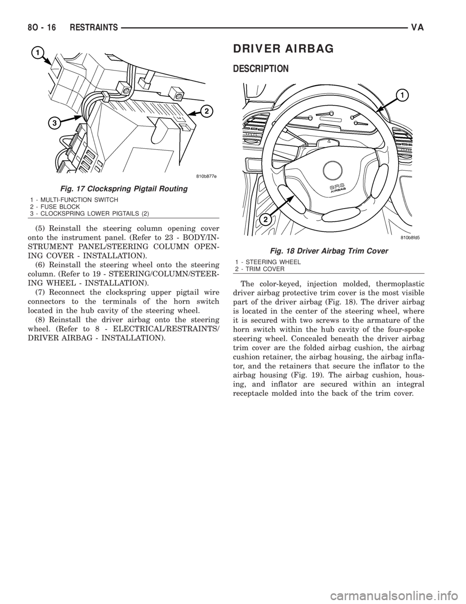
The color-keyed, injection molded, thermoplastic
driver airbag protective trim cover is the most visible
part of the driver airbag (Fig. 18). The driver airbag
is located in the center of the steering wheel, where
it is secured with two screws to the armature of the
horn switch within the hub cavity of the four-spoke
steering wheel. Concealed beneath the driver airbag
trim cover are the folded airbag cushion, the airbag
cushion retainer, the airbag housing, the airbag infla-
tor, and the retainers that secure the inflator to the
airbag housing (Fig. 19). The airbag cushion, hous-
ing, and inflator are secured within an integral
receptacle molded into the back of the trim cover.
Fig. 17 Clockspring Pigtail Routing
1 - MULTI-FUNCTION SWITCH
2 - FUSE BLOCK
3 - CLOCKSPRING LOWER PIGTAILS (2)
Fig. 18 Driver Airbag Trim Cover
1 - STEERING WHEEL
2 - TRIM COVER
8O - 16 RESTRAINTSVA
Page 1008 of 2305
The airbag used in this model is a Next Genera-
tion-type that complies with revised federal airbag
standards to deploy with less force than those used
in some prior models. A radial deploying fabric cush-
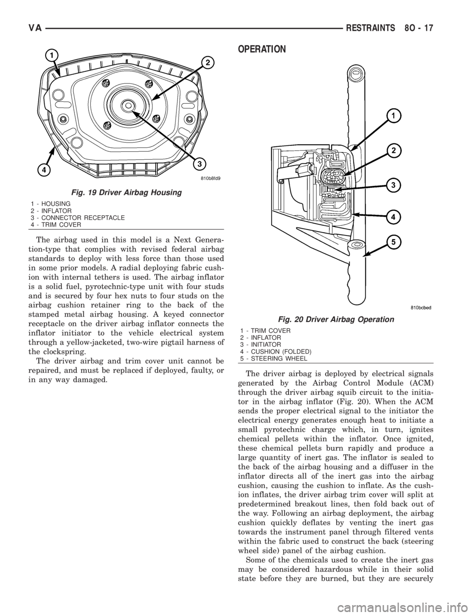
ion with internal tethers is used. The airbag inflator
is a solid fuel, pyrotechnic-type unit with four studs
and is secured by four hex nuts to four studs on the
airbag cushion retainer ring to the back of the
stamped metal airbag housing. A keyed connector
receptacle on the driver airbag inflator connects the
inflator initiator to the vehicle electrical system
through a yellow-jacketed, two-wire pigtail harness of
the clockspring.
The driver airbag and trim cover unit cannot be
repaired, and must be replaced if deployed, faulty, or
in any way damaged.
OPERATION
The driver airbag is deployed by electrical signals
generated by the Airbag Control Module (ACM)
through the driver airbag squib circuit to the initia-
tor in the airbag inflator (Fig. 20). When the ACM
sends the proper electrical signal to the initiator the
electrical energy generates enough heat to initiate a
small pyrotechnic charge which, in turn, ignites
chemical pellets within the inflator. Once ignited,
these chemical pellets burn rapidly and produce a
large quantity of inert gas. The inflator is sealed to
the back of the airbag housing and a diffuser in the
inflator directs all of the inert gas into the airbag
cushion, causing the cushion to inflate. As the cush-
ion inflates, the driver airbag trim cover will split at
predetermined breakout lines, then fold back out of
the way. Following an airbag deployment, the airbag
cushion quickly deflates by venting the inert gas
towards the instrument panel through filtered vents
within the fabric used to construct the back (steering
wheel side) panel of the airbag cushion.
Some of the chemicals used to create the inert gas
may be considered hazardous while in their solid
state before they are burned, but they are securely
Fig. 19 Driver Airbag Housing
1 - HOUSING
2 - INFLATOR
3 - CONNECTOR RECEPTACLE
4 - TRIM COVER
Fig. 20 Driver Airbag Operation
1 - TRIM COVER
2 - INFLATOR
3 - INITIATOR
4 - CUSHION (FOLDED)
5 - STEERING WHEEL
VARESTRAINTS 8O - 17
Page 1023 of 2305
out and connector of the vehicle wire harness located
within the driver side front seat riser.
The seat belt switch cannot be adjusted or repaired
and, if faulty or damaged, the entire driver side seat
belt buckle unit must be replaced.
OPERATION
The seat belt switch is designed to control a path
to ground for the seat belt switch sense input of the
Electro-Mechanical Instrument Cluster (EMIC). The
seat belt switch contact is actuated by the seat belt
latch plate being inserted in to the buckle. When the
seat belt latch plate is inserted into the buckle far
enough to be engaged by the seat belt buckle latch,
the switch leaf contact opens the seat belt switch
sense circuit ground path; and, when the seat belt
latch plate is released and extracted from the seat
belt buckle latch the switch leaf contact is released,
closing the circuit to ground.
The seat belt switch is connected is series between
ground and the seat belt switch sense input of the
instrument cluster. The seat belt switch receives
ground at all times through its pigtail wire connec-
tion to the vehicle wire harness from another take
out of the vehicle wire harness. An eyelet terminal
connector on the vehicle wire harness ground take
out is secured under a nut to a ground stud located
on the floor panel within the driver side front seat
riser. The seat belt switch may de diagnosed using
conventional diagnostic tools and methods.
SEAT BELT TENSIONER
DESCRIPTION
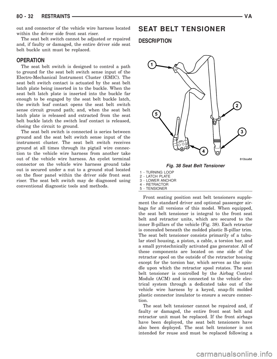
Front seating position seat belt tensioners supple-
ment the standard driver and optional passenger air-
bags for all versions of this model. When equipped,
the seat belt tensioner is integral to the front seat
belt and retractor units, which are secured to the
inner B-pillars of the vehicle (Fig. 38). Each retractor
is concealed beneath the molded plastic B-pillar trim.
The seat belt tensioner consists primarily of a tubu-
lar steel housing, a piston, a cable, a torsion bar, and
a small pyrotechnically activated gas generator. All of
these components are located on one side of the
retractor spool on the outside of the retractor housing
except for the torsion bar, which serves as the spin-
dle upon which the retractor spool rotates. The seat
belt tensioner is controlled by the Airbag Control
Module (ACM) and is connected to the vehicle elec-
trical system through a dedicated take out of the
vehicle wire harness by a keyed, snap-fit molded
plastic connector insulator to ensure a secure connec-
tion.
The seat belt tensioner cannot be repaired and, if
faulty or damaged, the entire front seat belt and
retractor unit must be replaced. If the front airbags
have been deployed, the seat belt tensioners have
also been deployed. The seat belt tensioner is not
intended for reuse and must be replaced following a
Fig. 38 Seat Belt Tensioner
1 - TURNING LOOP
2 - LATCH PLATE
3 - LOWER ANCHOR
4 - RETRACTOR
5 - TENSIONER
8O - 32 RESTRAINTSVA
Page 1026 of 2305
(8) Remove the seat belt turning loop height
adjuster from the inner B-pillar.
INSTALLATION
WARNING: To avoid personal injury or death, on
vehicles equipped with airbags, disable the supple-
mental restraint system before attempting any
steering wheel, steering column, airbag, seat belt
tensioner, or instrument panel component diagno-
sis or service. Disconnect and isolate the battery
negative (ground) cable, then wait two minutes for
the system capacitor to discharge before perform-
ing further diagnosis or service. This is the only
sure way to disable the supplemental restraint sys-
tem. Failure to take the proper precautions could
result in accidental airbag deployment.
WARNING: To avoid personal injury or death, during
and following any seat belt service, carefully
inspect all seat belts, buckles, mounting hardware,
retractors, and anchors for proper installation, oper-
ation, or damage. Replace any belt that is cut,
frayed, or torn. Straighten any belt that is twisted.
Tighten any loose fasteners. Replace any belt that
has a damaged or inoperative buckle or retractor.
Replace any belt that has a bent or damaged latch
plate or anchor plate. Never attempt to repair a seat
belt component. Always replace damaged or faulty
seat belt components with the correct, new and
unused replacement parts listed in the
DaimlerChrysler Mopar Parts Catalog.
(1) Position the seat belt turning loop height
adjuster onto the inner B-pillar (Fig. 42).
(2) Install and tighten the two screws that secure
the seat belt turning loop height adjuster to the
upper inner B-pillar. Tighten the screws to 35 N´m
(26 ft. lbs.).
(3) Position the front seat belt turning loop onto
the height adjuster on the upper B-pillar (Fig. 41).
(4) Install and tighten the nut that secures the
front seat belt turning loop to the height adjuster.
Tighten the nut to 35 N´m (26 ft. lbs.).
(5) Position the height adjuster trim to the upper
B-pillar so that the driver on the back of the trim
engages the lug of the height adjuster (Fig. 40).
(6) Reinstall the trim panel onto the inside of the
B-pillar. (Refer to 23 - BODY/INTERIOR/B-PILLAR
TRIM - INSTALLATION).
(7) Reconnect the battery negative cable.
SIDE CURTAIN AIRBAG
DESCRIPTION
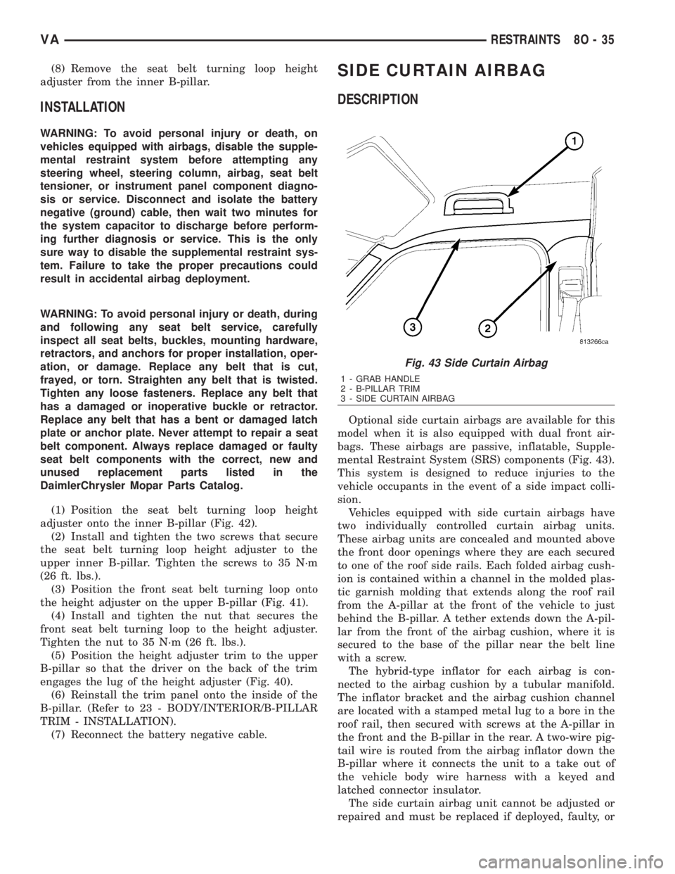
Optional side curtain airbags are available for this
model when it is also equipped with dual front air-
bags. These airbags are passive, inflatable, Supple-
mental Restraint System (SRS) components (Fig. 43).
This system is designed to reduce injuries to the
vehicle occupants in the event of a side impact colli-
sion.
Vehicles equipped with side curtain airbags have
two individually controlled curtain airbag units.
These airbag units are concealed and mounted above
the front door openings where they are each secured
to one of the roof side rails. Each folded airbag cush-
ion is contained within a channel in the molded plas-
tic garnish molding that extends along the roof rail
from the A-pillar at the front of the vehicle to just
behind the B-pillar. A tether extends down the A-pil-
lar from the front of the airbag cushion, where it is
secured to the base of the pillar near the belt line
with a screw.
The hybrid-type inflator for each airbag is con-
nected to the airbag cushion by a tubular manifold.
The inflator bracket and the airbag cushion channel
are located with a stamped metal lug to a bore in the
roof rail, then secured with screws at the A-pillar in
the front and the B-pillar in the rear. A two-wire pig-
tail wire is routed from the airbag inflator down the
B-pillar where it connects the unit to a take out of
the vehicle body wire harness with a keyed and
latched connector insulator.
The side curtain airbag unit cannot be adjusted or
repaired and must be replaced if deployed, faulty, or
Fig. 43 Side Curtain Airbag
1 - GRAB HANDLE
2 - B-PILLAR TRIM
3 - SIDE CURTAIN AIRBAG
VARESTRAINTS 8O - 35
Page 1038 of 2305

VEHICLE THEFT SECURITY
TABLE OF CONTENTS
page page
VEHICLE THEFT SECURITY
DESCRIPTION..........................1
OPERATION............................1
DIAGNOSIS AND TESTING - VEHICLE THEFT
SECURITY............................1
INTRUSION SENSOR
REMOVAL.............................1
INSTALLATION..........................2
SECURITY SYSTEM MODULE
REMOVAL.............................2
INSTALLATION..........................2SENTRY KEY REMOTE ENTRY MODULE
DESCRIPTION..........................2
OPERATION............................3
REMOVAL.............................3
INSTALLATION..........................4
SIREN
REMOVAL.............................4
INSTALLATION..........................4
TRANSPONDER KEY
DESCRIPTION..........................5
OPERATION............................5
VEHICLE THEFT SECURITY
DESCRIPTION
A vehicle theft alarm with a battery powered siren
is available as an option and includes interior moni-
toring, anti-tow away protection and rear window
monitoring based on the heater wires. The alarm is
automatically activated when the central locking sys-
tem is operated.
The alarm will sound when any of the following
occur:
²A door is opened
²A door is unlocked from inside the vehicle
²The hood is opened
²The vehicle is raised at the front or rear
²The trailer wire harness is disconnected
²Movements inside the vehicle
²The central locking is unlocked by a key at any
other door than the driver's door
The alarm is functional about 30 seconds after the
vehicle is locked using the RKE transmitter or the
key in the driver's door. Activation is indicated by the
indicator lights flashing three times and the warning
lamp flashing in the switch. If persons or animals
remain in the locked vehicle, the operator should
switch off the interior monitor to avoid a false alarm.
OPERATION
The anti-theft alarm is activated/deactivated by
locking/unlocking the vehicle with the remote trans-
mitter or with the key at the driver's door. The key
must be held in the locking position for more than
two seconds. Activation is indicated by the turn sig-
nal lights flashing once. Unlocking the vehicle at one
of the other doors will trigger an alarm.
The interior monitoring system included in the
anti-theft alarm is based on ultrasonics and triggersan alarm if an object intrudes the interior of the
vehicle or if any movement is detected inside the
vehicle. For proper and effective protection, all win-
dows and the sunroof must be closed.
To switch off the interior monitoring system and /
or the anti-tow away protection, a switch with LED
indicator light is provided in the switch panel. An
alarm button enables the operator to trigger an
alarm manually and to lock all doors if they are
closed. Triggering an alarm makes the horn sound
and the turn signals flash until the alarm is switched
off.
The anti-theft alarm control unit includes a gradi-
ent indicator as anti-tow away protection. The gradi-
ent indicator triggers an audible and visual alarm if
the vehicle is lifted (to tow away or to remove the
wheels). The alarm remains effective even if the bat-
tery is disconnected as the horn is powered by its
own battery. The interior monitoring system should
be switched off if people and/or animals are left in
the vehicle.
DIAGNOSIS AND TESTING - VEHICLE THEFT
SECURITY
Any diagnosis of the Vehicle Theft Security
system should begin with the use of a diagnos-
tic scan tool. Refer to the appropriate diagnos-
tic information.
INTRUSION SENSOR
REMOVAL
(1) Disconnect and isolate the battery negative
cable.
(2) Insert the tip of a small flat-bladed screwdriver
into the notch on one edge of the dome lamp/intru-
sion sensor unit housing to depress the retainer clip
VAVEHICLE THEFT SECURITY 8Q - 1
Page 1039 of 2305
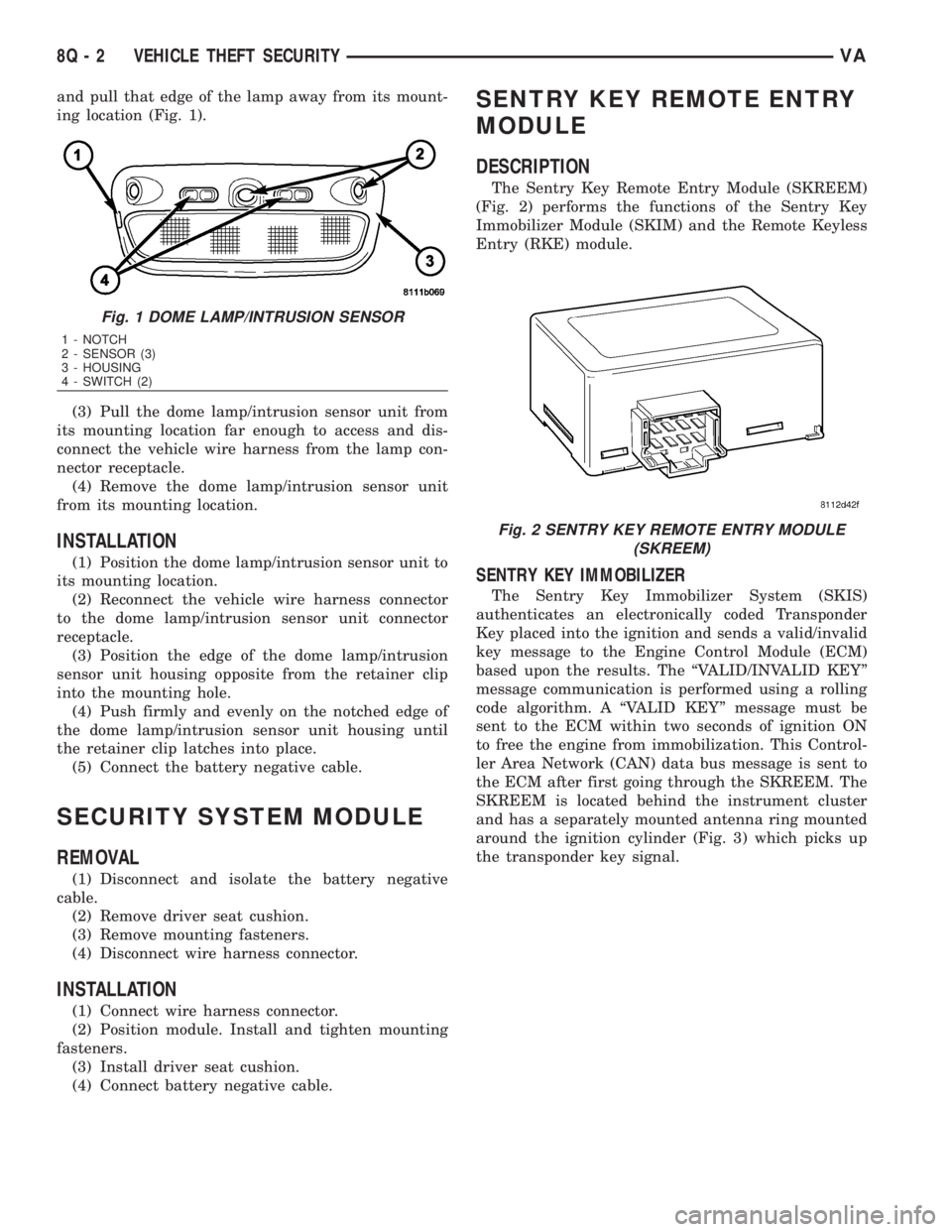
and pull that edge of the lamp away from its mount-
ing location (Fig. 1).
(3) Pull the dome lamp/intrusion sensor unit from
its mounting location far enough to access and dis-
connect the vehicle wire harness from the lamp con-
nector receptacle.
(4) Remove the dome lamp/intrusion sensor unit
from its mounting location.
INSTALLATION
(1) Position the dome lamp/intrusion sensor unit to
its mounting location.
(2) Reconnect the vehicle wire harness connector
to the dome lamp/intrusion sensor unit connector
receptacle.
(3) Position the edge of the dome lamp/intrusion
sensor unit housing opposite from the retainer clip
into the mounting hole.
(4) Push firmly and evenly on the notched edge of
the dome lamp/intrusion sensor unit housing until
the retainer clip latches into place.
(5) Connect the battery negative cable.
SECURITY SYSTEM MODULE
REMOVAL
(1) Disconnect and isolate the battery negative
cable.
(2) Remove driver seat cushion.
(3) Remove mounting fasteners.
(4) Disconnect wire harness connector.
INSTALLATION
(1) Connect wire harness connector.
(2) Position module. Install and tighten mounting
fasteners.
(3) Install driver seat cushion.
(4) Connect battery negative cable.
SENTRY KEY REMOTE ENTRY
MODULE
DESCRIPTION
The Sentry Key Remote Entry Module (SKREEM)
(Fig. 2) performs the functions of the Sentry Key
Immobilizer Module (SKIM) and the Remote Keyless
Entry (RKE) module.
SENTRY KEY IMMOBILIZER
The Sentry Key Immobilizer System (SKIS)
authenticates an electronically coded Transponder
Key placed into the ignition and sends a valid/invalid
key message to the Engine Control Module (ECM)
based upon the results. The ªVALID/INVALID KEYº
message communication is performed using a rolling
code algorithm. A ªVALID KEYº message must be
sent to the ECM within two seconds of ignition ON
to free the engine from immobilization. This Control-
ler Area Network (CAN) data bus message is sent to
the ECM after first going through the SKREEM. The
SKREEM is located behind the instrument cluster
and has a separately mounted antenna ring mounted
around the ignition cylinder (Fig. 3) which picks up
the transponder key signal.
Fig. 1 DOME LAMP/INTRUSION SENSOR
1 - NOTCH
2 - SENSOR (3)
3 - HOUSING
4 - SWITCH (2)
Fig. 2 SENTRY KEY REMOTE ENTRY MODULE
(SKREEM)
8Q - 2 VEHICLE THEFT SECURITYVA