2006 MERCEDES-BENZ SPRINTER engine coolant
[x] Cancel search: engine coolantPage 537 of 2305

TEST ACTION APPLICABILITY
1NOTE: If DTC P1611, P2306 or P2332 is present with this DTC, diagnose
DTCs P1611, P2306 or P2332 before diagnosing this DTC.
NOTE: If the ECM detects and stores a DTC, the ECM also stores the
engine/vehicle operating conditions under which the DTC was set. Some of
these conditions are displayed on the DRB at the same time the DTC is
displayed.
NOTE: Before erasing stored DTCs, record these conditions. Attempting to
duplicate these conditions may assist when checking for an active DTC.
NOTE: The engine oil must be at the proper level for this test to be valid.
Refer to the Service Information and ensure the engine oil level is at the
specified level.
Turn the ignition on.
With the DRB, erase ECM DTCs.
Start the engine several times, letting the engine run for at least 30 seconds at a
time.
With the DRB, read ECM DTCs.
Did this DTC set again?All
Ye s!Go To 2
No!Go To 10
2WARNING: WHEN THE ENGINE IS OPERATING, DO NOT STAND IN A
DIRECT LINE WITH THE FAN. DO NOT PUT YOUR HANDS NEAR THE
PULLEYS, BELTS OR FAN. DO NOT WEAR LOOSE CLOTHING.
Refer to any Technical Service Bulletins (TSB) that may apply.
Turn the ignition off.
NOTE: This DTC implies that the engine may be contaminated by water,
engine coolant or other material due to a mechanical or service failures
such as failed gaskets, seals, cracks or incorrectly installed components.
Inspect the engine for conditions referred to in the above note.
Were any of the above conditions present?All
Ye s!Repair as necessary.
Perform ROAD TEST VERIFICATION - VER-2.
No!Go To 3
3 Turn the ignition off.
Disconnect the Engine Oil Sensor harness connector.
Turn the ignition on.
Measure the voltage of the Engine Oil Sensor Signal circuit.
Select the appropriate voltage reading.All
Voltage is above 5.4 volts.
Go To 4
Voltage is between 4.7 and 5.4 volts.
Go To 5
Voltage is below 4.7 volts.
Go To 7
11 4
DRIVEABILITY - DIESEL
P2014-ENGINE OIL SENSOR OIL TEMPERATURE PLAUSIBILITY Ð
Continued
Page 565 of 2305

TEST ACTION APPLICABILITY
4 Turn the ignition off.
Disconnect the Camshaft Position Sensor harness connector.
Disconnect the ECM harness connectors.
Remove the Engine Control Relay.
Connect a jumper wire between cavity 30 and cavity 87 of the Engine Control Relay
connector.
Turn the ignition on.
Measure the voltage of the CMP Position Sensor Signal circuit.
Is the voltage below 1.0 volt?All
Ye s!Replace and program the Engine Control Module in accordance
with the Service Information.
Perform ROAD TEST VERIFICATION - VER-2.
No!Repair the Camshaft Position Sensor Signal circuit for a short to
voltage.
Perform ROAD TEST VERIFICATION - VER-2.
5 Turn the ignition off.
Disconnect the Camshaft Position Sensor harness connector.
Turn the ignition on.
Measure the voltage of the CMP Sensor 5-Volt Supply circuit.
Select the appropriate voltage reading.All
Voltage is above 5.4 volts.
Repair the CMP 5-Volt Supply circuit for a short to voltage.
Perform ROAD TEST VERIFICATION - VER-2.
Voltage is between 4.7 and 5.4 volts.
Go To 6
Voltage is below 4.7 volts.
Go To 10
6 Turn the ignition off.
Disconnect the CMP Sensor harness connector.
Disconnect the ECM harness connectors.
Measure the resistance of the Sensor Ground circuit between the CMP Sensor
harness connector and the ECM harness connector.
Is the resistance below 10.0 ohms?All
Ye s!Go To 7
No!Repair the Sensor Ground circuit for an open.
Perform ROAD TEST VERIFICATION - VER-2.
7 Turn the ignition on.
Disconnect the ECT Sensor harness connector.
Disconnect the Camshaft Position Sensor harness connector.
Connect one end of a jumper wire to the ECT Sensor signal circuit in the ECT Sensor
harness connector.
Connect the other end of the jumper wire to the Sensor Ground circuit in the
Camshaft Position Sensor harness connector.
With the DRBIIItin Engine, Sensors, read the Engine Coolant Temp volts.
Is the voltage below 0.5 volt?All
Ye s!Go To 8
No!Replace and program the ECM in accordance with the Service
Information.
Perform ROAD TEST VERIFICATION - VER-2.
142
DRIVEABILITY - DIESEL
P2043-CAMSHAFT POSITION SENSOR CIRCUIT OPEN CIRCUIT Ð
Continued
Page 669 of 2305

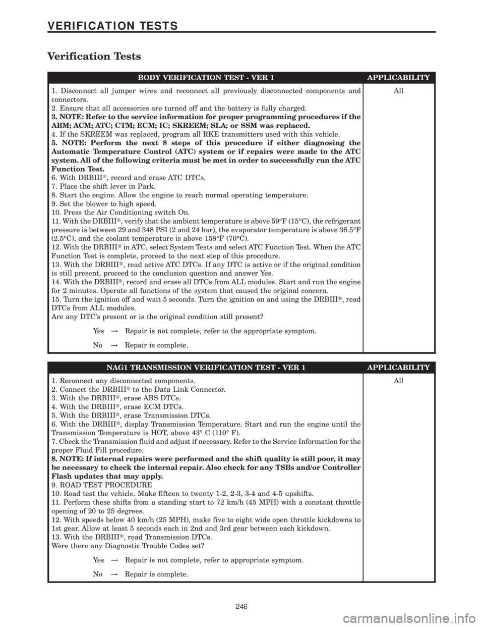
Verification Tests
BODY VERIFICATION TEST - VER 1 APPLICABILITY
1. Disconnect all jumper wires and reconnect all previously disconnected components and
connectors.
2. Ensure that all accessories are turned off and the battery is fully charged.
3. NOTE: Refer to the service information for proper programming procedures if the
ABM; ACM; ATC; CTM; ECM; IC; SKREEM; SLA; or SSM was replaced.
4. If the SKREEM was replaced, program all RKE transmitters used with this vehicle.
5. NOTE: Perform the next 8 steps of this procedure if either diagnosing the
Automatic Temperature Control (ATC) system or if repairs were made to the ATC
system. All of the following criteria must be met in order to successfully run the ATC
Function Test.
6. With DRBIIIt, record and erase ATC DTCs.
7. Place the shift lever in Park.
8. Start the engine. Allow the engine to reach normal operating temperature.
9. Set the blower to high speed.
10. Press the Air Conditioning switch On.
11. With the DRBIIIt, verify that the ambient temperature is above 59ÉF (15ÉC), the refrigerant
pressure is between 29 and 348 PSI (2 and 24 bar), the evaporator temperature is above 36.5ÉF
(2.5ÉC), and the coolant temperature is above 158ÉF (70ÉC).
12. With the DRBIIItin ATC, select System Tests and select ATC Function Test. When the ATC
Function Test is complete, proceed to the next step of this procedure.
13. With the DRBIIIt, read active ATC DTCs. If any DTC is active or if the original condition
is still present, proceed to the conclusion question and answer Yes.
14. With the DRBIIIt, record and erase all DTCs from ALL modules. Start and run the engine
for 2 minutes. Operate all functions of the system that caused the original concern.
15. Turn the ignition off and wait 5 seconds. Turn the ignition on and using the DRBIIIt, read
DTCs from ALL modules.
Are any DTC's present or is the original condition still present?All
Ye s!Repair is not complete, refer to the appropriate symptom.
No!Repair is complete.
NAG1 TRANSMISSION VERIFICATION TEST - VER 1 APPLICABILITY
1. Reconnect any disconnected components.
2. Connect the DRBIIItto the Data Link Connector.
3. With the DRBIIIt, erase ABS DTCs.
4. With the DRBIIIt, erase ECM DTCs.
5. With the DRBIIIt, erase Transmission DTCs.
6. With the DRBIIIt, display Transmission Temperature. Start and run the engine until the
Transmission Temperature is HOT, above 43É C (110É F).
7. Check the Transmission fluid and adjust if necessary. Refer to the Service Information for the
proper Fluid Fill procedure.
8. NOTE: If internal repairs were performed and the shift quality is still poor, it may
be necessary to check the internal repair. Also check for any TSBs and/or Controller
Flash updates that may apply.
9. ROAD TEST PROCEDURE
10. Road test the vehicle. Make fifteen to twenty 1-2, 2-3, 3-4 and 4-5 upshifts.
11. Perform these shifts from a standing start to 72 km/h (45 MPH) with a constant throttle
opening of 20 to 25 degrees.
12. With speeds below 40 km/h (25 MPH), make five to eight wide open throttle kickdowns to
1st gear. Allow at least 5 seconds each in 2nd and 3rd gear between each kickdown.
13. With the DRBIIIt, read Transmission DTCs.
Were there any Diagnostic Trouble Codes set?All
Ye s!Repair is not complete, refer to appropriate symptom.
No!Repair is complete.
246
VERIFICATION TESTS
Page 682 of 2305

ENGINE CONTROL MODULE C1 (OBD)CAV CIRCUIT FUNCTION
1 16BL FUEL INJECTOR NO. 1 HIGH-SIDE CONTROL
2 16BL/WT FUEL INJECTOR NO. 4 HIGH-SIDE CONTROL
3 16DG FUEL INJECTOR NO. 3 HIGH-SIDE CONTROL
4 20RD/WT FUEL PRESSURE SOLENOID 12 VOLT SUPPLY
8 18BL/GY FUEL TEMPERATURE SENSOR SIGNAL
10 20RD/YL ENGINE OIL SENSOR 5 VOLT SUPPLY
11 20GY/BL ENGINE OIL SENSOR SIGNAL
12 20BR/RD INTAKE PRESSURE SENSOR GROUND
13 20VT/DG INTAKE PRESSURE SENSOR SIGNAL
14 20BR/DG CAMSHAFT POSITION SENSOR GROUND
15 20DG/BK O2 1/1 PUMP CELL SIGNAL
20 18BK/YL WATER IN FUEL SENSOR SIGNAL
21 18BK/RD CRANKCASE HEATER SIGNAL
25 16BK FUEL INJECTOR NO. 2 HIGH-SIDE CONTROL
26 16BK/WT FUEL INJECTOR NO. 5 HIGH-SIDE CONTROL
28 18RD/BK FUEL QUANTITY SOLENOID 12 VOLT SUPPLY
31 20YL/BL MASS AIR FLOW SENSOR GROUND
32 18DG/BK FUEL TEMPERATURE SENSOR GROUND
35 20BR/BK SENSOR GROUND
36 20VT/RD INTAKE PRESSURE SENSOR 5 VOLT SUPPLY
37 20RD/BL CAMSHAFT POSITION SENSOR 5 VOLT SUPPLY
38 20YL/GY CAMSHAFT POSITION SENSOR SIGNAL
39 20GY O2 1/1 SENSOR CELL SIGNAL
40 20GY/WT O2 1/1 VIRTUAL GROUND
49 16BK/VT FUEL INJECTOR NO. 4 LOW-SIDE CONTROL
50 16BK/DG FUEL INJECTOR NO. 3 LOW-SIDE CONTROL
51 16BK/YL FUEL INJECTOR NO. 5 LOW-SIDE CONTROL
52 20BK/WT FUEL PRESSURE SOLENOID CONTROL
55 18BR WATER IN FUEL SENSOR GROUND
56 20BR/WT ENGINE COOLANT TEMPERATURE SENSOR GROUND
57 20DG/RD ENGINE COOLANT TEMPERATURE SENSOR SIGNAL
59 20DG/VT FUEL PRESSURE SENSOR SIGNAL
61 20BR/VT MASS AIR FLOW SENSOR 5 VOLT SUPPLY
62 20DG/YL O2 1/1 PUMP CELL CONTROL
72 20GY/BL O2 1/1 HEATER CONTROL
73 16BK/RD FUEL INJECTOR NO. 1 LOW-SIDE CONTROL
74 16BK/BL FUEL INJECTOR NO. 2 LOW-SIDE CONTROL
76 18BR/YL FUEL QUANTITY SOLENOID CONTROL
79 18BR/RD WATER IN FUEL SENSOR 12 VOLT SUPPLY
84 20BR/GY FUEL PRESSURE SENSOR GROUND
85 20YL/DG MASS AIR FLOW SENSOR SIGNAL
86 20RD/DG FUEL PRESSURE SENSOR 5 VOLT SUPPLY
87 20DG/WT CRANKSHAFT POSITION SENSOR SIGNAL NO. 1
88 20DG CRANKSHAFT POSITION SENSOR SIGNAL NO. 2
90 20DG/WT EGR VALVE CONTROL
91 18BK/BR CRANKCASE HEATER GROUND
93 16YL/DG BOOST PRESSURE SERVOMOTOR CONTROL
C
O
N
N
E
C
T
O
R
P
I
N
O
U
T
S
259
CONNECTOR PINOUTS
Page 683 of 2305

ENGINE CONTROL MODULE C2 (OBD)CAV CIRCUIT FUNCTION
1 16BK/RD FUSED ENGINE CONTROL RELAY OUTPUT
2 14BR GROUND
3 14BK/BL FUSED ENGINE CONTROL RELAY OUTPUT
4 14BR GROUND
5 14BK/BL FUSED ENGINE CONTROL RELAY OUTPUT
6 14BR GROUND
7 18RD S/C SWITCH 12 VOLT SUPPLY
8 18BR/WT HIGH IDLE ON SIGNAL
10 18WT/RD BOOST PRESSURE SENSOR 5 VOLT SUPPLY
11 18WT/DG BOOST PRESSURE SENSOR SIGNAL
12 18BR/WT SENSOR GROUND
13 18GY/DG ACCEL PEDAL POSITION SENSOR SIGNAL NO. 2
14 18BR/GY ACCEL PEDAL POSITION SENSOR GROUND NO. 2
17 18BR/DG KICKDOWN SWITCH SIGNAL
18 20DG/YL ENGINE RPM
19 18BK FUSED IGNITION SWITCH OUTPUT (RUN-START)
24 18BL/RD ACCEL PEDAL POSITION SENSOR 5 VOLT SUPPLY
25 18BL/DG ACCEL PEDAL POSITION SENSOR SIGNAL NO. 1
26 18BR/BL ACCEL PEDAL POSITION SENSOR GROUND NO. 1
28 18BR/DG INTAKE AIR TEMPERATURE SENSOR GROUND
31 20BL/YL K-ECM
32 20DG ENHANCED ACCIDENT REPORT DRIVER
36 18VT IGNITION SWITCH OUTPUT (START)
37 18DG ACCEL/SET SIGNAL
38 18BK VERIFICATION SIGNAL
42 18DG/WT INTAKE AIR TEMPERATURE SENSOR SIGNAL
43 18BK/RD GLOW PLUG MODULE CONTROL
44 18YL/BL ENGINE CONTROL RELAY CONTROL
50 18YL DECEL/SET SIGNAL
51 18GY OFF SIGNAL
52 18BL RESUME SIGNAL
53 20DG/WT CAN C BUS (+)
54 20DG CAN C BUS (-)
55 18BR/RD FUEL PUMP RELAY CONTROL
58 18VT/DG STARTER MOTOR RELAY CONTROL
ENGINE COOLANT TEMPERATURE SENSOR - BLACKCAV CIRCUIT FUNCTION
1 20BR/WT ENGINE COOLANT TEMPERATURE SENSOR GROUND
2 20DG/RD ENGINE COOLANT TEMPERATURE SENSOR SIGNAL
C
O
N
N
E
C
T
O
R
P
I
N
O
U
T
S
260
CONNECTOR PINOUTS
Page 708 of 2305

FASTENER IDENTIFICATION
DESCRIPTION
The SAE bolt strength grades range from grade 2
to grade 8. The higher the grade number, the greater
the bolt strength. Identification is determined by the
line marks on the top of each bolt head. The actual
bolt strength grade corresponds to the number of line
marks plus 2. The most commonly used metric bolt
strength classes are 9.8 and 10.9. The metric
strength class identification number is imprinted on
the head of the bolt. The higher the class number,
the greater the bolt strength. Some metric nuts are
imprinted with a single-digit strength class on the
nut face. Refer to the Fastener Identification and
Fastener Strength Charts (Fig. 2) and (Fig. 3).
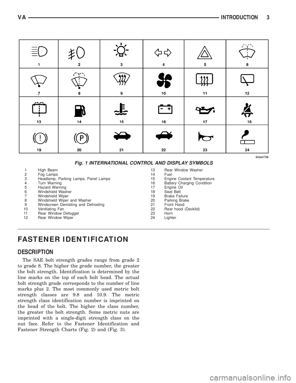
Fig. 1 INTERNATIONAL CONTROL AND DISPLAY SYMBOLS
1 High Beam 13 Rear Window Washer
2 Fog Lamps 14 Fuel
3 Headlamp, Parking Lamps, Panel Lamps 15 Engine Coolant Temperature
4 Turn Warning 16 Battery Charging Condition
5 Hazard Warning 17 Engine Oil
6 Windshield Washer 18 Seat Belt
7 Windshield Wiper 19 Brake Failure
8 Windshield Wiper and Washer 20 Parking Brake
9 Windscreen Demisting and Defrosting 21 Front Hood
10 Ventilating Fan 22 Rear hood (Decklid)
11 Rear Window Defogger 23 Horn
12 Rear Window Wiper 24 Lighter
VAINTRODUCTION 3
Page 716 of 2305

LUBRICATION & MAINTENANCE
TABLE OF CONTENTS
page page
FLUID TYPES
DESCRIPTION
PARTS AND LUBRICANT
RECOMMENDATIONS...................1
AUTOMATIC TRANSMISSION FLUID - NAG1 . 1
AXLE FLUID..........................2
BRAKE FLUID.........................2
HOAT COOLANT.......................2
ENGINE OIL - DIESEL ENGINES...........3
FUEL REQUIREMENTS - DIESEL ENGINE . . . 4
POWER STEERING FLUID...............5
OPERATION - AUTOMATIC TRANSMISSION
FLUID...............................5
FLUID CAPACITIES
SPECIFICATIONS - FLUID CAPACITIES.......5FLUID FILL/CHECK LOCATIONS
INSPECTION - FLUID FILL/CHECK
LOCATIONS..........................5
HOISTING
STANDARD PROCEDURE - HOISTING........5
JUMP STARTING
STANDARD PROCEDURE - JUMP STARTING . . 6
TOWING
STANDARD PROCEDURE - TOWING.........7
MAINTENANCE SCHEDULES
DESCRIPTION..........................8
INTERNATIONAL SYMBOLS
DESCRIPTION..........................9
FLUID TYPES
DESCRIPTION
PARTS AND LUBRICANT RECOMMENDATIONS
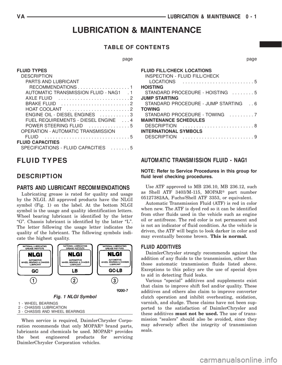
Lubricating grease is rated for quality and usage
by the NLGI. All approved products have the NLGI
symbol (Fig. 1) on the label. At the bottom NLGI
symbol is the usage and quality identification letters.
Wheel bearing lubricant is identified by the letter
ªGº. Chassis lubricant is identified by the latter ªLº.
The letter following the usage letter indicates the
quality of the lubricant. The following symbols indi-
cate the highest quality.
When service is required, DaimlerChrysler Corpo-
ration recommends that only MOPARtbrand parts,
lubricants and chemicals be used. MOPARtprovides
the best engineered products for servicing
DaimlerChrysler Corporation vehicles.
AUTOMATIC TRANSMISSION FLUID - NAG1
NOTE: Refer to Service Procedures in this group for
fluid level checking procedures.
Use ATF approved to MB 236.10, MB 236.12, such
as Shell ATF 3403/M-115, MOPARtpart number
05127382AA, Fuchs/Shell ATF 3353, or equivalent.
Automatic Transmission Fluid (ATF) is red in color
when new. The ATF is dyed red so it can be identified
from other fluids used in the vehicle such as engine
oil or antifreeze. The red color is not permanent and
is not an indicator of fluid condition. As the vehicle is
driven, the ATF will begin to look darker in color and
may eventually become brown.This is normal.
FLUID ADDITIVES
DaimlerChrysler strongly recommends against the
addition of any fluids to the transmission, other than
those automatic transmission fluids listed above.
Exceptions to this policy are the use of special dyes
to aid in detecting fluid leaks.
Various ªspecialº additives and supplements exist
that claim to improve shift feel and/or quality. These
additives and others also claim to improve converter
clutch operation and inhibit overheating, oxidation,
varnish, and sludge. These claims have not been sup-
ported to the satisfaction of DaimlerChrysler and
these additivesmust not be used.The use of trans-
mission ªsealersº should also be avoided, since they
may adversely affect the integrity of transmission
seals.
Fig. 1 NLGI Symbol
1 - WHEEL BEARINGS
2 - CHASSIS LUBRICATION
3 - CHASSIS AND WHEEL BEARINGS
VALUBRICATION & MAINTENANCE 0 - 1
Page 717 of 2305

AXLE FLUID
Use oils approved to MB 235.0 or 235.6, such as
Shell Spirax MB90, Caltex Hypoid LD, or MOPARt
part number 4874469, or equivalent. An API GL-5/
MIL-2105-E SAE 90 Hypoid Gear Oil may be substi-
tuted. Reduced axle durability may result if an
unapproved product is used.
BRAKE FLUID
Use brake fluid approved to MB 331.0, such as
Intac B026D, MOPARtBrake & Clutch Fluid, part
number 04549625AC, or equivalent. If the approved
product is not available, use a DOT 4 brake fluid:
minimum dry boiling point (ERBP) 500ÉF, minimum
wet boiling point (WERBP) 356ÉF, maximum viscos-
ity 1500 mm
2/s, conforming to FMVSS 116 and ISO
4925.
HOAT COOLANT
WARNING: ANTIFREEZE IS AN ETHYLENE-GLYCOL
BASE COOLANT AND IS HARMFUL IF SWAL-
LOWED OR INHALED. IF SWALLOWED, DRINK
TWO GLASSES OF WATER AND INDUCE VOMIT-
ING. IF INHALED, MOVE TO FRESH AIR AREA.
SEEK MEDICAL ATTENTION IMMEDIATELY. DO NOT
STORE IN OPEN OR UNMARKED CONTAINERS.
WASH SKIN AND CLOTHING THOROUGHLY AFTER
COMING IN CONTACT WITH ETHYLENE-GLYCOL.
KEEP OUT OF REACH OF CHILDREN. DISPOSE OF
GLYCOL BASE COOLANT PROPERLY, CONTACT
YOUR DEALER OR GOVERNMENT AGENCY FOR
LOCATION OF COLLECTION CENTER IN YOUR
AREA. DO NOT OPEN A COOLING SYSTEM WHEN
THE ENGINE IS AT OPERATING TEMPERATURE OR
HOT UNDER PRESSURE, PERSONAL INJURY CAN
RESULT. AVOID RADIATOR COOLING FAN WHEN
ENGINE COMPARTMENT RELATED SERVICE IS
PERFORMED, PERSONAL INJURY CAN RESULT.
CAUTION: Use of Propylene-Glycol based coolants
is not recommended, as they provide less freeze
protection and less corrosion protection.
The cooling system is designed around the coolant.
The coolant must accept heat from engine metal, in
the cylinder head area near the exhaust valves and
engine block. Then coolant carries the heat to the
radiator where the tube/fin radiator can transfer the
heat to the air.
The use of aluminum cylinder blocks, cylinder
heads, and water pumps requires special corrosion
protection. Use coolant approved to MB 325.0, such
as EURO Peak Coolant/Anti-freeze (OLD WORLD
INDUSTRIES), Zerex G05 or G48 (The Valvoline
Company), Glysantin G05 (BASF AG), MOPARtpart
number 05066386AA, or an equivalent Extended LifeCoolant with the HOAT inhibitor system. This cool-
ant offers the best engine cooling without corrosion
when mixed with 50% anti-freeze and 50% distilled
water to obtain a freeze point of -37ÉC (-34ÉF). If it
loses color or becomes contaminated, drain, flush,
and replace with fresh properly mixed coolant solu-
tion.
CAUTION: This coolant may not be mixed with any
other type of antifreeze. Mixing of coolants other
than specified (non-HOAT), may result in engine
damage that may not be covered under the new
vehicle warranty, and decreased corrosion protec-
tion.
CAUTION: Do not use coolant additives that are
claimed to improve engine cooling.
COOLANT PERFORMANCE
The required ethylene-glycol (antifreeze) and water
mixture depends upon climate and vehicle operating
conditions. The coolant performance of various mix-
tures follows:
Pure Water-Water can absorb more heat than a
mixture of water and ethylene-glycol. This is for pur-
pose of heat transfer only. Water also freezes at a
higher temperature and allows corrosion.
100 percent Ethylene-Glycol-The corrosion
inhibiting additives in ethylene-glycol need the pres-
ence of water to dissolve. Without water, additives
form deposits in system. These act as insulation
causing temperature to rise. The increased tempera-
ture can result in engine detonation. In addition, 100
percent ethylene-glycol freezes at -22ÉC (-8ÉF).
50/50 Ethylene-Glycol and Water-Is the recom-
mended mixture, it provides protection against freez-
ing to -37ÉC (-34ÉF). The antifreeze concentration
must alwaysbe a minimum of 44 percent, year-
round in all climates. If percentage is lower, engine
parts may be eroded by cavitation. Maximum protec-
tion against freezing is provided with a 68 percent
antifreeze concentration, which prevents freezing
down to -67.7ÉC (-90ÉF). A higher percentage will
freeze at a warmer temperature. Also, a higher per-
centage of antifreeze can cause the engine to over-
heat because specific heat of antifreeze is lower than
that of water.
CAUTION: Richer antifreeze mixtures cannot be
measured with normal field equipment and can
cause problems associated with 100 percent ethyl-
ene-glycol.
0 - 2 LUBRICATION & MAINTENANCEVA