2006 MERCEDES-BENZ SPRINTER engine coolant
[x] Cancel search: engine coolantPage 720 of 2305
Do not blend other specific fuel additives with die-
sel fuel. They only result in unnecessary cost, and
may be harmful to the engine operation.
POWER STEERING FLUID
No fluid service required. Filled with Power Steer-
ing Fluid approved to MB 236.3, such as Mobil
ATF-D (Exxon Mobil Corporation) or equivalent.
OPERATION - AUTOMATIC TRANSMISSION
FLUID
The automatic transmission fluid is selected based
upon several qualities. The fluid must provide a high
level of protection for the internal components by
providing a lubricating film between adjacent metal
components. The fluid must also be thermally stable
so that it can maintain a consistent viscosity through
a large temperature range. If the viscosity stays con-
stant through the temperature range of operation,
transmission operation and shift feel will remain con-
sistent. Transmission fluid must also be a good con-
ductor of heat. The fluid must absorb heat from the
internal transmission components and transfer that
heat to the transmission case.
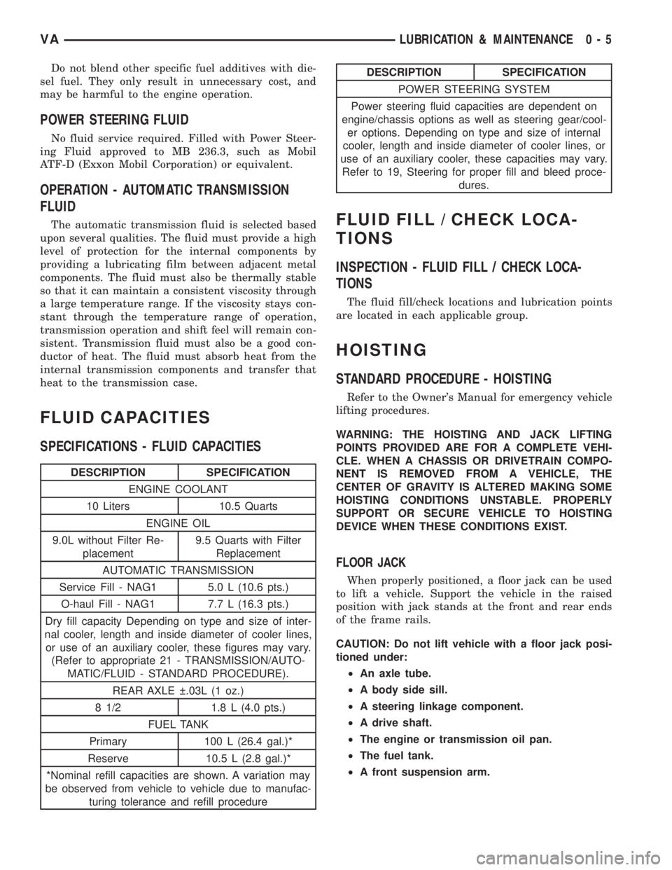
FLUID CAPACITIES
SPECIFICATIONS - FLUID CAPACITIES
DESCRIPTION SPECIFICATION
ENGINE COOLANT
10 Liters 10.5 Quarts
ENGINE OIL
9.0L without Filter Re-
placement9.5 Quarts with Filter
Replacement
AUTOMATIC TRANSMISSION
Service Fill - NAG1 5.0 L (10.6 pts.)
O-haul Fill - NAG1 7.7 L (16.3 pts.)
Dry fill capacity Depending on type and size of inter-
nal cooler, length and inside diameter of cooler lines,
or use of an auxiliary cooler, these figures may vary.
(Refer to appropriate 21 - TRANSMISSION/AUTO-
MATIC/FLUID - STANDARD PROCEDURE).
REAR AXLE .03L (1 oz.)
8 1/2 1.8 L (4.0 pts.)
FUEL TANK
Primary 100 L (26.4 gal.)*
Reserve 10.5 L (2.8 gal.)*
*Nominal refill capacities are shown. A variation may
be observed from vehicle to vehicle due to manufac-
turing tolerance and refill procedure
DESCRIPTION SPECIFICATION
POWER STEERING SYSTEM
Power steering fluid capacities are dependent on
engine/chassis options as well as steering gear/cool-
er options. Depending on type and size of internal
cooler, length and inside diameter of cooler lines, or
use of an auxiliary cooler, these capacities may vary.
Refer to 19, Steering for proper fill and bleed proce-
dures.
FLUID FILL / CHECK LOCA-
TIONS
INSPECTION - FLUID FILL / CHECK LOCA-
TIONS
The fluid fill/check locations and lubrication points
are located in each applicable group.
HOISTING
STANDARD PROCEDURE - HOISTING
Refer to the Owner's Manual for emergency vehicle
lifting procedures.
WARNING: THE HOISTING AND JACK LIFTING
POINTS PROVIDED ARE FOR A COMPLETE VEHI-
CLE. WHEN A CHASSIS OR DRIVETRAIN COMPO-
NENT IS REMOVED FROM A VEHICLE, THE
CENTER OF GRAVITY IS ALTERED MAKING SOME
HOISTING CONDITIONS UNSTABLE. PROPERLY
SUPPORT OR SECURE VEHICLE TO HOISTING
DEVICE WHEN THESE CONDITIONS EXIST.
FLOOR JACK
When properly positioned, a floor jack can be used
to lift a vehicle. Support the vehicle in the raised
position with jack stands at the front and rear ends
of the frame rails.
CAUTION: Do not lift vehicle with a floor jack posi-
tioned under:
²An axle tube.
²A body side sill.
²A steering linkage component.
²A drive shaft.
²The engine or transmission oil pan.
²The fuel tank.
²A front suspension arm.
VALUBRICATION & MAINTENANCE 0 - 5
Page 723 of 2305
effect panels. If necessary, remove the wheels from
the lifted end of the vehicle and lower the vehicle
closer to the ground, to increase the ground clearance
at the opposite end of the vehicle. Install lug nuts on
wheel attaching studs to retain brake drums.
RAMP ANGLE
If a vehicle with flat-bed towing equipment is used,
the approach ramp angle should not exceed 15
degrees.
TOWING WHEN KEYS ARE NOT AVAILABLE
When the vehicle is locked and keys are not avail-
able, use a flat bed hauler. A Wheel-lift or Sling-type
device can be used provided all the wheels are lifted
off the ground using tow dollies.
MAINTENANCE SCHEDULES
DESCRIPTION
The use of special lubricant additives is not recom-
mended. The use of such additives may affect the
warranty rights. With regard to legal stipulations
concerning emissions control, please note that
engines have to be serviced and adjusted in accor-
dance with special instructions and using special
measuring equipment. Modifications to or interfer-
ence with the emissions control systems are not per-
missible.
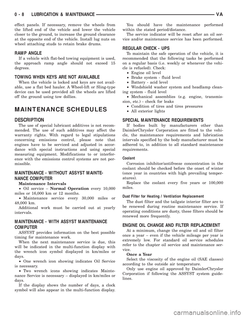
MAINTENANCE - WITHOUT ASSYST MAINTE-
NANCE COMPUTER
Maintenance Intervals
²Oil service ±Normal Operationevery 10,000
miles or 16,000 km or 12 months.
²Maintenance service every 30,000 miles or
48,000 km.
Additional work must be carried out at yearly
intervals.
MAINTENANCE - WITH ASSYST MAINTENANCE
COMPUTER
ASSYST provides information on the best possible
timing for maintenance work.
When the next maintenance service is due, this
will be indicated in the multi-function display with
the wrench icon symbol displayed in km/miles or
days.
²One wrench icon showing indicates Oil Service
is necessary.
²Two wrench icons showing indicates Mainte-
nance Service is necessary ± displayed in km/miles or
days.
If the display shows the number of days, a clock
symbol will also appear in the multi-function display.You should have the maintenance performed
within the stated period/distance.
The service indicator will be reset after an oil ser-
vice and/or maintenance service has been performed.
REGULAR CHECK - UPS
To maintain the safe operation of the vehicle, it is
recommended that the following tasks be performed
on a regular basis (i.e. weekly or whenever the vehi-
cle is refueled). Check:
²Engine oil level
²Brake system - fluid level
²Battery - acid level
²Windshield washer system and headlamp clean-
ing system - fluid level
²Mechanical assemblies (e.g. engine, transmis-
sion, etc.) - check for leaks
²Condition of tires and tires pressures
²All exterior lights
SPECIAL MAINTENANCE REQUIREMENTS
If bodies built by manufacturers other than
DaimlerChrysler Corporation are fitted to the vehi-
cle, the maintenance requirements and lubrication
intervals specified by the body manufacturer must be
adhered to, in addition to all standard maintenance
requirements.
Coolant
Corrosion inhibitor/antifreeze concentration in the
coolant should be checked before the onset of winter
(once year in countries with high prevailing temper-
atures).
Replace the coolant every five years or 100,000
miles.
Dust Filter for Heating / Ventilation Replacement
The dust filter and the tailgate interior filter are to
be renewed during routine maintenance service. If
operating conditions are dusty, these filters should be
renewed more frequently.
ENGINE OIL CHANGE AND FILTER REPLACEMENT
At a minimum, change the engine oil and oil filter
once a year ± even if the vehicle mileage per year is
extremely low. For standard oil service schedules
refer to the chapter oil service and maintenance ser-
vice.
Once a Year
Select the viscosity of the engine oil (SAE classes)
according to the outside air temperature.
Only use engine oil approved by DaimlerChrysler
Corporation if following the ASSYST system guide-
lines.
0 - 8 LUBRICATION & MAINTENANCEVA
Page 724 of 2305

SCOPE OF WORK FOR MAINTENANCE SERVICE
Oil Service
²Engine: Oil change and filter replacement
Check fluid levels of the following system, refill as neces-
sary.
²If fluid is lost, trace and eliminate cause - as a
separate order.
²Power-assisted steering
Lubrication work:
²Trailer tow hitch (original equipment)
Maintenance
²ASSYST maintenance computer reset
Function check
²Signalling system, warning and indicator lamps
²Headlamps, exterior lighting
²Windshield wipers, windshield washer system
Check for leaks and damage
²Check for abrasion points and ensure that lines
are correctly routed!
²All lines and hoses, sensor cables
²Rubber boots on front axle drive shafts, rubber
boots on front axle suspension ball joints, shock
absorbers
²Check fluid levels for the following systems, cor-
rect as necessary
NOTE: Should there be a loss of fluid which cannot
be explained by regular use, trace and eliminate the
cause.
²Engine cooling system. Check corrosion inhibi-
tor/antifreeze, refill as necessary.
²Hydraulic brake system
²Battery
²Windshield washer system
Engine
²Fuel filter renewal - Every oil service
²Air cleaner with maintenance indicator:
²Check degree of contamination.
²Air cleaner filter element renewed as necessary.
Chassis and body
²Trailer coupling: Check operation, play and
retaining fixtures
²Secondary rubber springs: Visual check
²Tire pressures: Correct as necessary, including
spare tire
²Check thickness of brake pads
²Brake test
²Check condition of steering mechanism
²Heating/ventilation dust filter renewal
ADDITIONAL MAINTENANCE WORK
Automatic transmission once only at 80,000 miles / 128000
km
²Oil and filter change
During every second maintenance service
²Air cleaner without maintenance indicator:
²Air cleaner filter element renewal
²Check poly-V-belt for wear and signs of damage
During every fourth maintenance service
²Change rear axle fluid
ADDITIONAL MAINTENANCE WORK AFTER YEARS
Every 2 years
²Change brake fluid.
Every 3 years
²Air cleaner filter element renewal (note installa-
tion date)
Every 15 years or 100,000 miles
²Coolant renewal
²Note coolant composition
INTERNATIONAL SYMBOLS
DESCRIPTION
DaimlerChrysler Corporation uses international
symbols to identify engine compartment lubricant
and fluid inspection and fill locations (Fig. 3).
Fig. 3 INTERNATIONAL SYMBOLS
VALUBRICATION & MAINTENANCE 0 - 9
Page 828 of 2305
COOLING
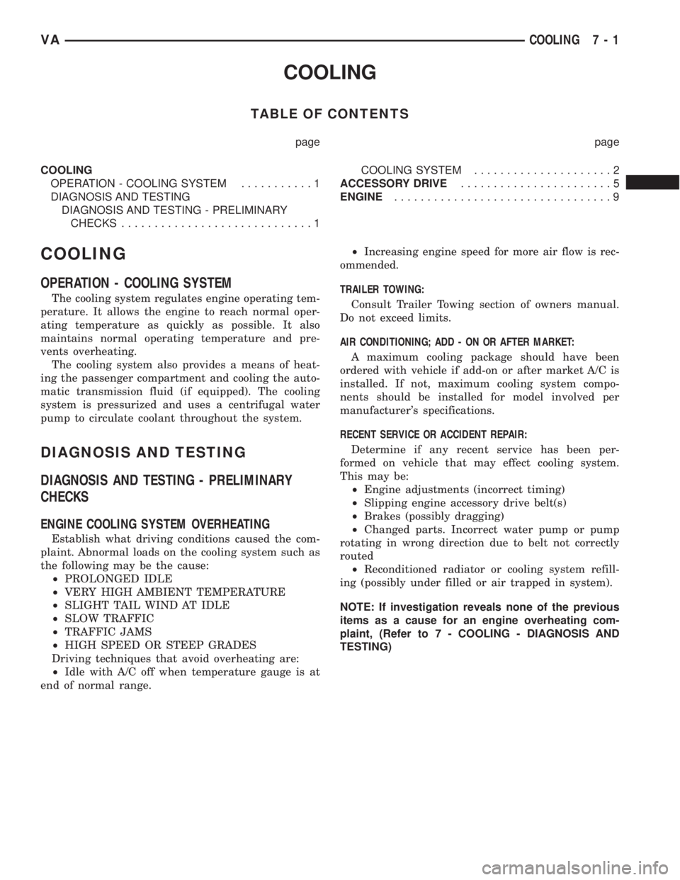
TABLE OF CONTENTS
page page
COOLING
OPERATION - COOLING SYSTEM...........1
DIAGNOSIS AND TESTING
DIAGNOSIS AND TESTING - PRELIMINARY
CHECKS.............................1COOLING SYSTEM.....................2
ACCESSORY DRIVE.......................5
ENGINE.................................9
COOLING
OPERATION - COOLING SYSTEM
The cooling system regulates engine operating tem-
perature. It allows the engine to reach normal oper-
ating temperature as quickly as possible. It also
maintains normal operating temperature and pre-
vents overheating.
The cooling system also provides a means of heat-
ing the passenger compartment and cooling the auto-
matic transmission fluid (if equipped). The cooling
system is pressurized and uses a centrifugal water
pump to circulate coolant throughout the system.
DIAGNOSIS AND TESTING
DIAGNOSIS AND TESTING - PRELIMINARY
CHECKS
ENGINE COOLING SYSTEM OVERHEATING
Establish what driving conditions caused the com-
plaint. Abnormal loads on the cooling system such as
the following may be the cause:
²PROLONGED IDLE
²VERY HIGH AMBIENT TEMPERATURE
²SLIGHT TAIL WIND AT IDLE
²SLOW TRAFFIC
²TRAFFIC JAMS
²HIGH SPEED OR STEEP GRADES
Driving techniques that avoid overheating are:
²Idle with A/C off when temperature gauge is at
end of normal range.²Increasing engine speed for more air flow is rec-
ommended.
TRAILER TOWING:
Consult Trailer Towing section of owners manual.
Do not exceed limits.
AIR CONDITIONING; ADD - ON OR AFTER MARKET:
A maximum cooling package should have been
ordered with vehicle if add-on or after market A/C is
installed. If not, maximum cooling system compo-
nents should be installed for model involved per
manufacturer's specifications.
RECENT SERVICE OR ACCIDENT REPAIR:
Determine if any recent service has been per-
formed on vehicle that may effect cooling system.
This may be:
²Engine adjustments (incorrect timing)
²Slipping engine accessory drive belt(s)
²Brakes (possibly dragging)
²Changed parts. Incorrect water pump or pump
rotating in wrong direction due to belt not correctly
routed
²Reconditioned radiator or cooling system refill-
ing (possibly under filled or air trapped in system).
NOTE: If investigation reveals none of the previous
items as a cause for an engine overheating com-
plaint, (Refer to 7 - COOLING - DIAGNOSIS AND
TESTING)
VACOOLING 7 - 1
Page 829 of 2305
COOLING SYSTEM
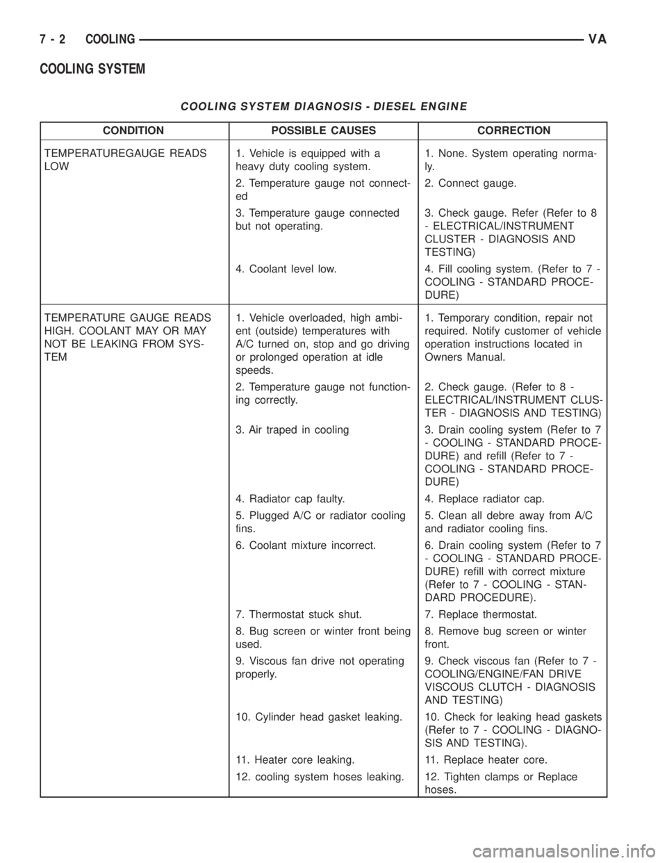
COOLING SYSTEM DIAGNOSIS - DIESEL ENGINE
CONDITION POSSIBLE CAUSES CORRECTION
TEMPERATUREGAUGE READS
LOW1. Vehicle is equipped with a
heavy duty cooling system.1. None. System operating norma-
ly.
2. Temperature gauge not connect-
ed2. Connect gauge.
3. Temperature gauge connected
but not operating.3. Check gauge. Refer (Refer to 8
- ELECTRICAL/INSTRUMENT
CLUSTER - DIAGNOSIS AND
TESTING)
4. Coolant level low. 4. Fill cooling system. (Refer to 7 -
COOLING - STANDARD PROCE-
DURE)
TEMPERATURE GAUGE READS
HIGH. COOLANT MAY OR MAY
NOT BE LEAKING FROM SYS-
TEM1. Vehicle overloaded, high ambi-
ent (outside) temperatures with
A/C turned on, stop and go driving
or prolonged operation at idle
speeds.1. Temporary condition, repair not
required. Notify customer of vehicle
operation instructions located in
Owners Manual.
2. Temperature gauge not function-
ing correctly.2. Check gauge. (Refer to 8 -
ELECTRICAL/INSTRUMENT CLUS-
TER - DIAGNOSIS AND TESTING)
3. Air traped in cooling 3. Drain cooling system (Refer to 7
- COOLING - STANDARD PROCE-
DURE) and refill (Refer to 7 -
COOLING - STANDARD PROCE-
DURE)
4. Radiator cap faulty. 4. Replace radiator cap.
5. Plugged A/C or radiator cooling
fins.5. Clean all debre away from A/C
and radiator cooling fins.
6. Coolant mixture incorrect. 6. Drain cooling system (Refer to 7
- COOLING - STANDARD PROCE-
DURE) refill with correct mixture
(Refer to 7 - COOLING - STAN-
DARD PROCEDURE).
7. Thermostat stuck shut. 7. Replace thermostat.
8. Bug screen or winter front being
used.8. Remove bug screen or winter
front.
9. Viscous fan drive not operating
properly.9. Check viscous fan (Refer to 7 -
COOLING/ENGINE/FAN DRIVE
VISCOUS CLUTCH - DIAGNOSIS
AND TESTING)
10. Cylinder head gasket leaking. 10. Check for leaking head gaskets
(Refer to 7 - COOLING - DIAGNO-
SIS AND TESTING).
11. Heater core leaking. 11. Replace heater core.
12. cooling system hoses leaking. 12. Tighten clamps or Replace
hoses.
7 - 2 COOLINGVA
Page 830 of 2305

CONDITION POSSIBLE CAUSES CORRECTION
13. Brakes dragging. 13. Check brakes. (Refer to 5 -
BRAKES/HYDRAULIC/MECHANI-
CAL - DIAGNOSIS AND TESTING)
TEMPERATURE GAUGE READ-
ING INCONSISTENT ( ERRATIC,
CYCLES OR FLUCTUATES)1. Heavy duty cooling system, ex-
tream cold ambient (outside) tem-
perature or heater blower motor in
high position.1. None. System operating norma-
ly.
2. Temperature gauge or gauge
sensor defective.2. Check gauge. (Refer to 8 -
ELECTRICAL/INSTRUMENT CLUS-
TER - DIAGNOSIS AND TESTING)
3. Temporary heavy usage or load. 3. None. Normal condition.
4. Air traped in cooling system. 4. Fill cooling system (Refer to 7 -
COOLING - STANDARD PROCE-
DURE).
5. Water pump 5. Replace water pump.
6. Air leak on suction side of water
pump.6. Check for leak. (Refer to 7 -
COOLING - DIAGNOSIS AND
TESTING)
RADIATOR CAP LEAKING STEAM
AND /OR COOLANT INTO RES-
ERVOIR BOTTLE. (TEMPERA-
TURE GAUGE MAY READ HIGH)1. Radiator cap defective. 1. Replace radiator cap.
2. Radiator neck surface damaged. 2. Replace radiator.
HOSE OR HOSES COLLAPSE
WHEN ENGINE IS COOLING.1. Vacuum created in cooling sys-
tem on engine cool-down is not
being relieved through coolant re-
servior/overflow system.1. Replace radiator cap, check vent
hose between radiator and reser-
voir bottle for blockage also check
reservoir bottle vent for blockage.
NOISY FAN 1. Fan blade(s) loose, damaged. 1. Replace fan blade assembly.
2. Thermal viscous fan drive. 2. None. Normal condition.
3. Fan blades striking surrounding
objects.3. Locate contact point and repair
as necessary.
4. Thermal viscous fan drive bear-
ing.4. Replace viscous fan drive as-
sembly.
5. Obstructed air flow through radi-
ator.5. Remove obstruction.
INADEQUATE AIR CONDITIONER
PERFORMANCE (COOLING SYS-
TEM SUSPECTED)1. Radiator and/or A/C condenser
air flow obstructed.1. Remove obstruction and/or
clean.
2. Thermal viscous fan drive not
working.2. Check fan drive. (Refer to 7 -
COOLING/ENGINE/FAN DRIVE
VISCOUS CLUTCH - DIAGNOSIS
AND TESTING)
3. Air seals around radiator dam-
aged or missing.3. Inspect air seals, repair or re-
place as necessary.
VACOOLING 7 - 3
Page 836 of 2305

ENGINE
TABLE OF CONTENTS
page page
COOLANT
DESCRIPTION..........................9
DIAGNOSIS AND TESTING
COOLING SYSTEM LEAKS..............10
STANDARD PROCEDURE
ADDING ADDITIONAL COOLANT.........12
DRAINING COOLING SYSTEM...........12
REFILLING COOLING SYSTEM...........13
COOLANT LEVEL SENSOR
REMOVAL.............................13
INSTALLATION.........................14
RADIATOR FAN
REMOVAL.............................14
INSTALLATION.........................14
ENGINE BLOCK HEATER
REMOVAL.............................14
INSTALLATION.........................15
ENGINE COOLANT TEMP SENSOR
DESCRIPTION.........................15REMOVAL.............................15
INSTALLATION.........................15
ENGINE COOLANT THERMOSTAT
REMOVAL.............................16
INSTALLATION.........................16
FAN DRIVE VISCOUS CLUTCH
REMOVAL.............................17
INSTALLATION.........................17
RADIATOR
REMOVAL.............................17
INSTALLATION.........................19
RADIATOR PRESSURE CAP
DESCRIPTION.........................19
OPERATION...........................20
DIAGNOSIS AND TESTING - RADIATOR
PRESSURE CAP......................20
WATER PUMP
REMOVAL.............................20
INSTALLATION.........................22
COOLANT
DESCRIPTION
Coolant flows through the engine water jackets
and cylinder heads absorbing heat produced by the
engine during operation. The coolant carries heat to
the radiator and heater core. Here it is transferred to
ambient air passing through the radiator and heater
core fins.
The required ethylene-glycol (antifreeze) and water
mixture depends upon the climate and vehicle oper-
ating conditions. The recommended mixture of 50/50
ethylene-glycol and water will provide protection
against freezing to -37É C (-35É F). The antifreeze
concentrationmust alwaysbe a minimum of 44 per-
cent, year-round in all climates.If percentage is
lower than 44 percent, engine parts may be
eroded by cavitation, and cooling system com-
ponents may be severely damaged by corrosion.
Maximum protection against freezing is provided
with a 68 percent antifreeze concentration, which
prevents freezing down to -67.7É C (-90É F). A higher
percentage will freeze at a warmer temperature.
Also, a higher percentage of antifreeze can cause the
engine to overheat because the specific heat of anti-
freeze is lower than that of water.100 Percent Ethylene - Glycol - Should Not Be Used in
Chrysler Vehicles
Use of 100 percent ethylene-glycol will cause for-
mation of additive deposits in the system, as the cor-
rosion inhibitive additives in ethylene-glycol require
the presence of water to dissolve. The deposits act as
insulation, causing temperatures to rise to as high as
149É C (300É F). This temperature is hot enough to
melt plastic and soften solder. The increased temper-
ature can result in engine detonation. In addition,
100 percent ethylene-glycol freezes at -22É C (-8É F ).
Propylene - glycol Formulations - Should Not Be Used in
Chrysler Vehicles
Propylene-glycol formulations do not meet
Chrysler coolant specifications.It's overall effec-
tive temperature range is smaller than that of ethyl-
ene-glycol. The freeze point of 50/50 propylene-glycol
and water is -32É C (-26É F). 5É C higher than ethyl-
ene-glycol's freeze point. The boiling point (protection
against summer boil-over) of propylene-glycol is 125É
C (257ÉF)at96.5 kPa (14 psi), compared to 128É C
(263É F) for ethylene-glycol. Use of propylene-glycol
can result in boil-over or freeze-up in Chrysler vehi-
cles, which are designed for ethylene-glycol. Propy-
lene glycol also has poorer heat transfer
characteristics than ethylene glycol. This can
increase cylinder head temperatures under certain
conditions.
VAENGINE 7 - 9
Page 837 of 2305
Propylene - glycol / Ethylene - glycol Mixtures - Should Not
Be Used in Chrysler Vehicles
Propylene-glycol/ethylene-glycol Mixtures can
cause the destabilization of various corrosion inhibi-
tors, causing damage to the various cooling system
components. Also, once ethylene-glycol and propy-
lene-glycol based coolants are mixed in the vehicle,
conventional methods of determining freeze point will
not be accurate. Both the refractive index and spe-
cific gravity differ between ethylene glycol and propy-
lene glycol.
CAUTION: Richer antifreeze mixtures cannot be
measured with normal field equipment and can
cause problems associated with 100 percent ethyl-
ene-glycol.
DIAGNOSIS AND TESTING
COOLING SYSTEM LEAKS
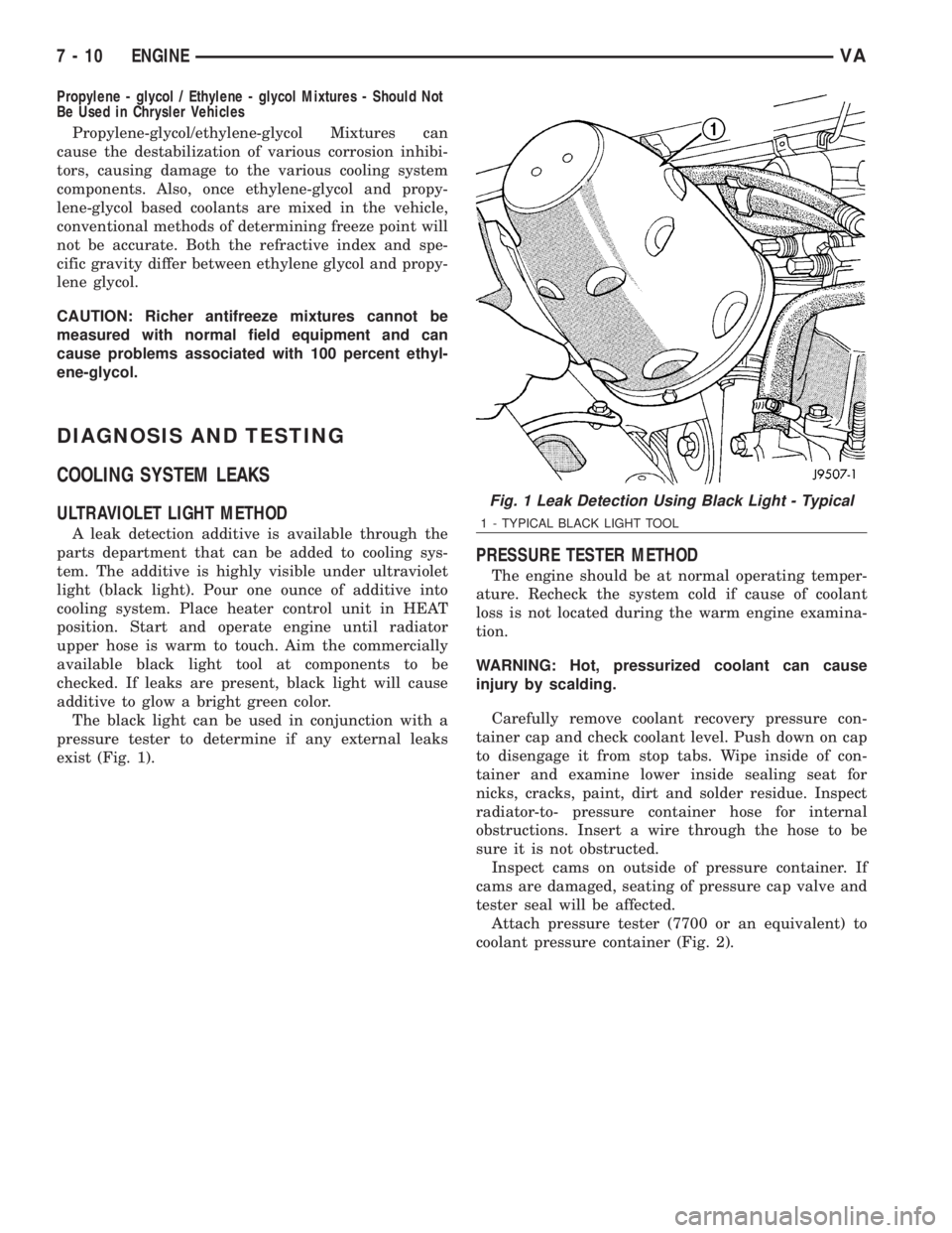
ULTRAVIOLET LIGHT METHOD
A leak detection additive is available through the
parts department that can be added to cooling sys-
tem. The additive is highly visible under ultraviolet
light (black light). Pour one ounce of additive into
cooling system. Place heater control unit in HEAT
position. Start and operate engine until radiator
upper hose is warm to touch. Aim the commercially
available black light tool at components to be
checked. If leaks are present, black light will cause
additive to glow a bright green color.
The black light can be used in conjunction with a
pressure tester to determine if any external leaks
exist (Fig. 1).
PRESSURE TESTER METHOD
The engine should be at normal operating temper-
ature. Recheck the system cold if cause of coolant
loss is not located during the warm engine examina-
tion.
WARNING: Hot, pressurized coolant can cause
injury by scalding.
Carefully remove coolant recovery pressure con-
tainer cap and check coolant level. Push down on cap
to disengage it from stop tabs. Wipe inside of con-
tainer and examine lower inside sealing seat for
nicks, cracks, paint, dirt and solder residue. Inspect
radiator-to- pressure container hose for internal
obstructions. Insert a wire through the hose to be
sure it is not obstructed.
Inspect cams on outside of pressure container. If
cams are damaged, seating of pressure cap valve and
tester seal will be affected.
Attach pressure tester (7700 or an equivalent) to
coolant pressure container (Fig. 2).
Fig. 1 Leak Detection Using Black Light - Typical
1 - TYPICAL BLACK LIGHT TOOL
7 - 10 ENGINEVA