2006 MERCEDES-BENZ SPRINTER low oil pressure
[x] Cancel search: low oil pressurePage 724 of 2305

SCOPE OF WORK FOR MAINTENANCE SERVICE
Oil Service
²Engine: Oil change and filter replacement
Check fluid levels of the following system, refill as neces-
sary.
²If fluid is lost, trace and eliminate cause - as a
separate order.
²Power-assisted steering
Lubrication work:
²Trailer tow hitch (original equipment)
Maintenance
²ASSYST maintenance computer reset
Function check
²Signalling system, warning and indicator lamps
²Headlamps, exterior lighting
²Windshield wipers, windshield washer system
Check for leaks and damage
²Check for abrasion points and ensure that lines
are correctly routed!
²All lines and hoses, sensor cables
²Rubber boots on front axle drive shafts, rubber
boots on front axle suspension ball joints, shock
absorbers
²Check fluid levels for the following systems, cor-
rect as necessary
NOTE: Should there be a loss of fluid which cannot
be explained by regular use, trace and eliminate the
cause.
²Engine cooling system. Check corrosion inhibi-
tor/antifreeze, refill as necessary.
²Hydraulic brake system
²Battery
²Windshield washer system
Engine
²Fuel filter renewal - Every oil service
²Air cleaner with maintenance indicator:
²Check degree of contamination.
²Air cleaner filter element renewed as necessary.
Chassis and body
²Trailer coupling: Check operation, play and
retaining fixtures
²Secondary rubber springs: Visual check
²Tire pressures: Correct as necessary, including
spare tire
²Check thickness of brake pads
²Brake test
²Check condition of steering mechanism
²Heating/ventilation dust filter renewal
ADDITIONAL MAINTENANCE WORK
Automatic transmission once only at 80,000 miles / 128000
km
²Oil and filter change
During every second maintenance service
²Air cleaner without maintenance indicator:
²Air cleaner filter element renewal
²Check poly-V-belt for wear and signs of damage
During every fourth maintenance service
²Change rear axle fluid
ADDITIONAL MAINTENANCE WORK AFTER YEARS
Every 2 years
²Change brake fluid.
Every 3 years
²Air cleaner filter element renewal (note installa-
tion date)
Every 15 years or 100,000 miles
²Coolant renewal
²Note coolant composition
INTERNATIONAL SYMBOLS
DESCRIPTION
DaimlerChrysler Corporation uses international
symbols to identify engine compartment lubricant
and fluid inspection and fill locations (Fig. 3).
Fig. 3 INTERNATIONAL SYMBOLS
VALUBRICATION & MAINTENANCE 0 - 9
Page 786 of 2305
(13) Connect propeller shaft to pinion flange.
NOTE: On dual rear wheel axle install axle shafts.
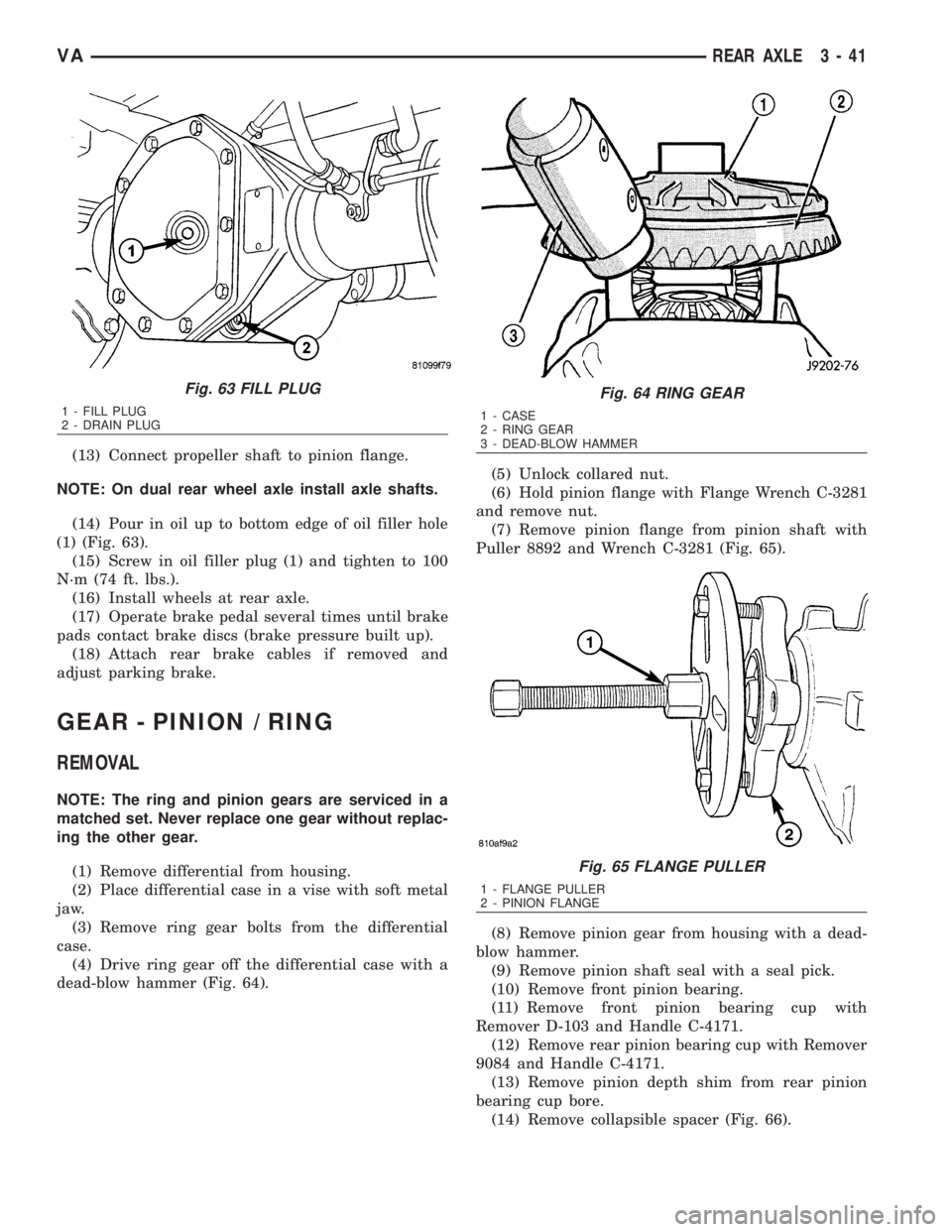
(14) Pour in oil up to bottom edge of oil filler hole
(1) (Fig. 63).
(15) Screw in oil filler plug (1) and tighten to 100
N´m (74 ft. lbs.).
(16) Install wheels at rear axle.
(17) Operate brake pedal several times until brake
pads contact brake discs (brake pressure built up).
(18) Attach rear brake cables if removed and
adjust parking brake.
GEAR - PINION / RING
REMOVAL
NOTE: The ring and pinion gears are serviced in a
matched set. Never replace one gear without replac-
ing the other gear.
(1) Remove differential from housing.
(2) Place differential case in a vise with soft metal
jaw.
(3) Remove ring gear bolts from the differential
case.
(4) Drive ring gear off the differential case with a
dead-blow hammer (Fig. 64).(5) Unlock collared nut.
(6) Hold pinion flange with Flange Wrench C-3281
and remove nut.
(7) Remove pinion flange from pinion shaft with
Puller 8892 and Wrench C-3281 (Fig. 65).
(8) Remove pinion gear from housing with a dead-
blow hammer.
(9) Remove pinion shaft seal with a seal pick.
(10) Remove front pinion bearing.
(11) Remove front pinion bearing cup with
Remover D-103 and Handle C-4171.
(12) Remove rear pinion bearing cup with Remover
9084 and Handle C-4171.
(13) Remove pinion depth shim from rear pinion
bearing cup bore.
(14) Remove collapsible spacer (Fig. 66).
Fig. 63 FILL PLUG
1 - FILL PLUG
2 - DRAIN PLUG
Fig. 64 RING GEAR
1 - CASE
2 - RING GEAR
3 - DEAD-BLOW HAMMER
Fig. 65 FLANGE PULLER
1 - FLANGE PULLER
2 - PINION FLANGE
VAREAR AXLE 3 - 41
Page 836 of 2305

ENGINE
TABLE OF CONTENTS
page page
COOLANT
DESCRIPTION..........................9
DIAGNOSIS AND TESTING
COOLING SYSTEM LEAKS..............10
STANDARD PROCEDURE
ADDING ADDITIONAL COOLANT.........12
DRAINING COOLING SYSTEM...........12
REFILLING COOLING SYSTEM...........13
COOLANT LEVEL SENSOR
REMOVAL.............................13
INSTALLATION.........................14
RADIATOR FAN
REMOVAL.............................14
INSTALLATION.........................14
ENGINE BLOCK HEATER
REMOVAL.............................14
INSTALLATION.........................15
ENGINE COOLANT TEMP SENSOR
DESCRIPTION.........................15REMOVAL.............................15
INSTALLATION.........................15
ENGINE COOLANT THERMOSTAT
REMOVAL.............................16
INSTALLATION.........................16
FAN DRIVE VISCOUS CLUTCH
REMOVAL.............................17
INSTALLATION.........................17
RADIATOR
REMOVAL.............................17
INSTALLATION.........................19
RADIATOR PRESSURE CAP
DESCRIPTION.........................19
OPERATION...........................20
DIAGNOSIS AND TESTING - RADIATOR
PRESSURE CAP......................20
WATER PUMP
REMOVAL.............................20
INSTALLATION.........................22
COOLANT
DESCRIPTION
Coolant flows through the engine water jackets
and cylinder heads absorbing heat produced by the
engine during operation. The coolant carries heat to
the radiator and heater core. Here it is transferred to
ambient air passing through the radiator and heater
core fins.
The required ethylene-glycol (antifreeze) and water
mixture depends upon the climate and vehicle oper-
ating conditions. The recommended mixture of 50/50
ethylene-glycol and water will provide protection
against freezing to -37É C (-35É F). The antifreeze
concentrationmust alwaysbe a minimum of 44 per-
cent, year-round in all climates.If percentage is
lower than 44 percent, engine parts may be
eroded by cavitation, and cooling system com-
ponents may be severely damaged by corrosion.
Maximum protection against freezing is provided
with a 68 percent antifreeze concentration, which
prevents freezing down to -67.7É C (-90É F). A higher
percentage will freeze at a warmer temperature.
Also, a higher percentage of antifreeze can cause the
engine to overheat because the specific heat of anti-
freeze is lower than that of water.100 Percent Ethylene - Glycol - Should Not Be Used in
Chrysler Vehicles
Use of 100 percent ethylene-glycol will cause for-
mation of additive deposits in the system, as the cor-
rosion inhibitive additives in ethylene-glycol require
the presence of water to dissolve. The deposits act as
insulation, causing temperatures to rise to as high as
149É C (300É F). This temperature is hot enough to
melt plastic and soften solder. The increased temper-
ature can result in engine detonation. In addition,
100 percent ethylene-glycol freezes at -22É C (-8É F ).
Propylene - glycol Formulations - Should Not Be Used in
Chrysler Vehicles
Propylene-glycol formulations do not meet
Chrysler coolant specifications.It's overall effec-
tive temperature range is smaller than that of ethyl-
ene-glycol. The freeze point of 50/50 propylene-glycol
and water is -32É C (-26É F). 5É C higher than ethyl-
ene-glycol's freeze point. The boiling point (protection
against summer boil-over) of propylene-glycol is 125É
C (257ÉF)at96.5 kPa (14 psi), compared to 128É C
(263É F) for ethylene-glycol. Use of propylene-glycol
can result in boil-over or freeze-up in Chrysler vehi-
cles, which are designed for ethylene-glycol. Propy-
lene glycol also has poorer heat transfer
characteristics than ethylene glycol. This can
increase cylinder head temperatures under certain
conditions.
VAENGINE 7 - 9
Page 838 of 2305

Operate tester pump to apply 103.4 kPa (15 psi)
pressure to system. If hoses enlarge excessively or
bulges while testing, replace as necessary. Observe
gauge pointer and determine condition of cooling sys-
tem according to following criteria:
Holds Steady:If pointer remains steady for two
minutes, serious coolant leaks are not present in sys-
tem. However, there could be an internal leak that
does not appear with normal system test pressure. If
it is certain that coolant is being lost and leaks can-
not be detected, inspect for interior leakage or per-
form Internal Leakage Test.
Drops Slowly:Indicates a small leak or seepage
is occurring. Examine all connections for seepage or
slight leakage with a flashlight. Inspect radiator,
hoses, gasket edges and heater. Seal small leak holes
with a Sealer Lubricant (or equivalent). Repair leak
holes and inspect system again with pressure
applied.
Drops Quickly:Indicates that serious leakage is
occurring. Examine system for external leakage. If
leaks are not visible, inspect for internal leakage.
Large radiator leak holes should be repaired by a
reputable radiator repair shop.
INTERNAL LEAKAGE INSPECTION
Remove engine oil pan drain plug and drain a
small amount of engine oil. If coolant is present in
the pan, it will drain first because it is heavier than
oil. An alternative method is to operate engine for a
short period to churn the oil. After this is done,
remove engine dipstick and inspect for water glob-ules. Also inspect transmission dipstick for water
globules and transmission fluid cooler for leakage.
WARNING: WITH RADIATOR PRESSURE TESTER
TOOL INSTALLED ON RADIATOR, DO NOT ALLOW
PRESSURE TO EXCEED 110 KPA (20 PSI). PRES-
SURE WILL BUILD UP QUICKLY IF A COMBUSTION
LEAK IS PRESENT. TO RELEASE PRESSURE,
ROCK TESTER FROM SIDE TO SIDE. WHEN
REMOVING TESTER, DO NOT TURN TESTER MORE
THAN 1/2 TURN IF SYSTEM IS UNDER PRESSURE.
Operate engine without pressure cap on coolant
container until thermostat opens. Attach a Pressure
Tester to container. If pressure builds up quickly it
indicates a combustion leak exists. This is usually
the result of a cylinder head gasket leak or crack in
engine. Repair as necessary.
If there is not an immediate pressure increase,
pump the Pressure Tester. Do this until indicated
pressure is within system range of 110 kPa (16 psi).
Fluctuation of gauge pointer indicates compression or
combustion leakage into cooling system.
Because the vehicle is equipped with a catalytic
converter,do notremove spark plug cables or short
out cylinders to isolate compression leak.
If the needle on dial of pressure tester does not
fluctuate, race engine a few times to check for an
abnormal amount of coolant or steam. This would be
emitting from exhaust pipe. Coolant or steam from
exhaust pipe may indicate a faulty cylinder head gas-
ket, cracked engine cylinder block or cylinder head.
A convenient check for exhaust gas leakage into
cooling system is provided by a commercially avail-
able Block Leak Check tool. Follow manufacturers
instructions when using this product.
COMBUSTION LEAKAGE TEST - WITHOUT PRES-
SURE TESTER
DO NOT WASTE reusable coolant. If solution is
clean, drain coolant into a clean and suitably marked
container for reuse.
WARNING: Do not remove cylinder block drain
plugs or loosen radiator drain with system hot and
under pressure. serious burns from coolant can
occur.
Drain sufficient coolant to allow thermostat
removal.
Remove accessory drive belt.
Add coolant to pressure container to bring level to
within 6.3 mm (1/4 in) of top of thermostat housing.
CAUTION: Avoid overheating. Do not operate
engine for an excessive period of time. Open drain-
cock immediately after test to eliminate boil over.
Fig. 2 PRESSURE TESTING
1 - PRESSURE RESERVOIR CAP
2 - PRESSURE RESERVOIR
3 - PRESSURE TESTER
VAENGINE 7 - 11
Page 843 of 2305

(3) Refill coolant system to proper level with
proper mixture of coolant (Refer to 7 - COOLING/
ENGINE/COOLANT - STANDARD PROCEDURE).
(4) Install engine cover (Refer to 9 - ENGINE -
INSTALLATION).
(5) Connect negative battery cable.
WARNING: Use extreme caution when engine is
operating. Do not stand in a direct line with fan. do
not put your hands near pulleys, belts or fan. Do
not wear loose clothes.
(6) Start engine and inspect for leaks.
ENGINE COOLANT THERMO-
STAT
REMOVAL
WARNING: RISK OF INJURY TO SKIN AND EYES
FROM SCALDING WITH HOT COOLANT. RISK OF
POISONING FROM SWALLOWING COOLANT. DO
NOT OPEN COOLING SYSTEM UNLESS COOLANT
TEMPERATURE IS BELOW 90ÉC (194ÉF). OPEN CAP
SLOWLY TO RELEASE PRESSURE. STORE COOL-
ANT IN SUITABLE AND APPROPRIATELY MARKED
CONTAINER. WEAR PROTECTIVE GLOVES,
CLOTHES AND EYE WEAR.
NOTE: Inspect condition of all clamps and hoses,
replace as necessary.
(1) Disconnect negative battery cable.
(2) Partially drain engine coolant (Refer to 7 -
COOLING/ENGINE/COOLANT - STANDARD PRO-
CEDURE).
(3) Unplug connector, pull off locking element and
pull out coolant temperature sensor.
(4) Detach air intake hose at charge air distribu-
tion pipe.
(5) Detach coolant hoses at thermostat housing.
(6) Unscrew cap at oil filter housing.
(7) Remove thermostat housing (Fig. 8).(8) Clean all sealing surfaces.
INSTALLATION
(1) Clean all sealing surfaces.
(2) Position and install thermostat housing with
new gasket (Fig. 8). Tighten bolts to 9N´m (80
lbs.in.).
NOTE: Inspect condition of all clamps and hoses,
replace as necessary.
(3) Install cap at oil filter housing.
(4) Connect coolant hoses and vent hose (Fig. 8).
(5) Attach air intake hose at charge air distribu-
tion pipe.
(6) Close coolant drain.
(7) Connect negative battery cable.
(8) Fill coolant system to proper level with appro-
priate coolant mixture (Refer to 7 - COOLING/EN-
GINE/COOLANT - STANDARD PROCEDURE).
WARNING: USE EXTREME CAUTION WHEN ENGINE
IS OPERATING. DO NOT STAND IN DIRECT LINE
WITH FAN. DO NOT PUT YOUR HANDS NEAR PUL-
LEYS, BELTS OR FAN. DO NOT WEAR LOOSE
CLOTHES.
(9) Start engine and inspect for leaks.
Fig. 8 THERMOSTAT HOUSING ASSEMBLY
1 - O-RING
2 - CLAMP
3 - COOLANT TEMPERATURE SENSOR
4 - FUEL LINE W/BRACKET
5 - THERMOSTAT HOUSING ASSEMBLY
6 - COOLANT HOSE
7 - CLAMP
8 - COOLANT HOSE
9 - GASKET
7 - 16 ENGINEVA
Page 846 of 2305

(17) Take off charge air cooler together with cool-
ing loop of the steering at the radiator (Fig. 10).
(18) Remove bottom radiator trim (Fig. 10).
(19) Detach coolant hose at radiator.
(20) Detach coolant pipe together with coolant
hose at the fan shroud.
(21) Remove radiator fan shroud (Fig. 10).
INSTALLATION
(1) Install fan shroud to radiator (Fig. 10).
(2) Attach coolant pipe with hoses to fan shroud
(Fig. 10).
(3) Attach coolant hose at radiator (Fig. 10).
(4) Install bottom radiator trim (Fig. 10).
(5) Install charge air cooler along with cooling loop
of the power steering, to radiator (Fig. 10).
(6) Install radiator assembly into the rubber grom-
mets (Fig. 9).
(7) Install both right and left side radiator trim
panels (Fig. 9).
(8) Attach the transmission cooler lines (Fig. 9).
(9) Attach coolant hose to the bottom right of the
radiator (Fig. 9).
(10) Attach both power steering hydraulic lines
(Fig. 9).
(11) Connect coolant level sensor electrical connec-
tor (Fig. 9).
(12) Connect coolant hoses to the coolant reservoir,
radiator and water pump (Fig. 9).(13) Attach air intake pipe at the body.
(14) Attach charge air hose at air intake.
(15) Attach charge air hose at turbocharger.
(16) Install A/C condenser.
(17) Install front bumper.
(18) Install front end cross member.
(19) Refill power steering to proper level.
(20) Refill transmission to proper level.
(21) Close radiator drain plug and refill the cooling
system (Refer to 7 - COOLING/ENGINE/COOLANT -
STANDARD PROCEDURE).
(22) Recharge air conditioning (Refer to 24 -
HEATING & AIR CONDITIONING/PLUMBING -
STANDARD PROCEDURE).
(23) Run engine until warm and check for leaks.
RADIATOR PRESSURE CAP
DESCRIPTION
All vehicles are equipped with a pressure cap (Fig.
11). This cap releases pressure at some point within
a range of 124-145 kPa (18-21 psi). The pressure
relief point (in pounds) is engraved on top of the cap
The cooling system will operate at pressures
slightly above atmospheric pressure. This results in a
higher coolant boiling point allowing increased radi-
ator cooling capacity. The cap contains a spring-
loaded pressure relief valve. This valve opens when
system pressure reaches the release range of 124-145
kPa (18-21 psi).
A rubber gasket seals the radiator filler neck. This
is done to maintain vacuum during coolant cool-down
and to prevent leakage when system is under pres-
sure.
Fig. 10 RADIATOR AND FAN SHROUD
1 - CLIP
2 - SHROUD
3 - RADIATOR
4 - BOTTOM RADIATOR TRIM PANEL
5 - CHARGE AIR COOLER
6 - TOP RADIATOR TRIM PANEL
7 - POWER STEERING COOLER LOOP
VAENGINE 7 - 19
Page 859 of 2305

ECM Control Strategy The engine control module
is involved with a variety of functions such as: (Fig.
3)
²Individual injector activation
²Engine idle speed control to ensure smooth
engine idling independent of engine load
²Ride comfort function such as anti jerk control:
The CDI control module detects irregularities in
engine speed (resulting, for example, from load
changes or gear shift) from the signal supplied by the
crankshaft position sensor and reduces them by
adjusting the quantity injected into each of the cylin-
ders
²Constant RPM (high idle feature) for ambulance
vehicle bodies equipped with electrical appliances
²Starter control, immobilizer, cruise control, kick
down, air conditioner
²Maintenance computer ASSYST (optional)
²Glow plug for pre-heating, post heating and
intermittent heating
²Error code memory/diagnostics, communication
interface for diagnosis and handling the fault codes
²The maximum vehicle speed is programmable
from 19±82 m.p.h. The standard is 82 m.p.h.
Fig. 2 ECM
1 - MASS AIR FLOW SENSOR 8 - CHARGE AIR PRESSURE SENSOR
2 - TURBOCHARGER SERVO MOTOR 9 - CHARGE AIR TEMPERATURE SENSOR
3 - CAMSHAFT POSITION SENSOR 10 - COOLANT TEMPERATURE SENSOR
4 - ENGINE OIL SENSOR 11 - FUEL RAIL PRESSURE SENSOR
5 - CRANKSHAFT POSITION SENSOR 12 - FUEL TEMPERATURE SENSOR
6 - PRESSURE REGULATOR VALVE 13 - FUEL QUANTITY CONTROL VALVE
7 - EGR VALVE 14 - AIR INTAKE PRESSURE SENSOR
8E - 4 ELECTRONIC CONTROL MODULESVA
Page 904 of 2305
REAR WINDOW DEFOGGER
RELAY
DESCRIPTION
The left and right rear window defogger (EBL)
relays are International Standards Organization
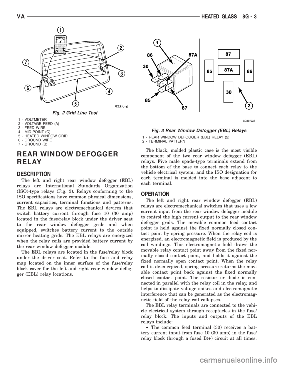
(ISO)-type relays (Fig. 3). Relays conforming to the
ISO specifications have common physical dimensions,
current capacities, terminal functions and patterns.
The EBL relays are electromechanical devices that
switch battery current through fuse 10 (30 amp)
located in the fuse/relay block under the driver seat
to the rear window defogger grids and when
equipped, switches battery current to the outside
mirror heating grids. The EBL relays are energized
when the relay coils are provided battery current by
the rear window defogger module.
The EBL relays are located in the fuse/relay block
under the driver seat. Refer to the fuse and relay
map located on the inner surface of the fuse/relay
block cover for the left and right rear window defog-
ger (EBL) relay locations.The black, molded plastic case is the most visible
component of the two rear window defogger (EBL)
relays. Five male spade-type terminals extend from
the bottom of the base to connect each relay to the
vehicle electrical system, and the ISO designation for
each terminal is molded into the base adjacent to
each terminal.
OPERATION
The left and right rear window defogger (EBL)
relays are electromechanical switches that uses a low
current input from the rear window defogger module
to control the high current output to the rear window
defogger grids. The movable common feed contact
point is held against the fixed normally closed con-
tact point by spring pressure. When the relay coil is
energized, an electromagnetic field is produced by the
coil windings. This electromagnetic field draws the
movable relay contact point away from the fixed nor-
mally closed contact point, and holds it against the
fixed normally open contact point. When the relay
coil is de-energized, spring pressure returns the mov-
able contact point back against the fixed normally
closed contact point. The resistor or diode is con-
nected in parallel with the relay coil in the relay, and
helps to dissipate voltage spikes and electromagnetic
interference that can be generated as the electromag-
netic field of the relay coil collapses.
The EBL relay terminals are connected to the vehi-
cle electrical system through receptacles in the fuse/
relay block. The inputs and outputs of the EBL
relays include:
²The common feed terminal (30) receives a bat-
tery current input from fuse 10 (30 amp) in the fuse/
relay block through a fused B(+) circuit at all times.
Fig. 2 Grid Line Test
1 - VOLTMETER
2 - VOLTAGE FEED (A)
3 - FEED WIRE
4 - MID-POINT (C)
5 - HEATED WINDOW GRID
6 - GROUND WIRE
7 - GROUND (B)
Fig. 3 Rear Window Defogger (EBL) Relays
1 - REAR WINDOW DEFOGGER (EBL) RELAY (2)
2 - TERMINAL PATTERN
VAHEATED GLASS 8G - 3