2006 MERCEDES-BENZ SPRINTER low oil pressure
[x] Cancel search: low oil pressurePage 546 of 2305

TEST ACTION APPLICABILITY
17 Refer to the appropriate Service Information and refer to Diagnosis and Testing Fuel
Delivery System table.
NOTE: The following is a list of problems that can cause fuel pressure to
deviate from specification: restricted fuel filter or fuel lines, failed fuel
pressure solenoid, air in fuel system, failed fuel sending unit, contaminated
fuel, faulty injector.
Were there any problems with the Fuel Delivery System?All
Ye s!Repair as necessary in accordance with the Service Information.
Perform ROAD TEST VERIFICATION - VER-2.
No!Go To 18
18 Refer to each of the following symptoms in the Driveability category.
CHECKING THE FUEL PRESSURE SOLENOID CIRCUITS
CHECKING THE FUEL QUANTITY SOLENOID CIRCUITS
CHECKING THE FUEL PRESSURE SENSOR CIRCUITS
Were any problems found?All
Ye s!Repair as necessary.
Perform ROAD TEST VERIFICATION - VER-2.
No!Go To 19
19NOTE: An injector that sticks open can cause this DTC. A sticking injector
will cause the engine to misfire and emit excessive black smoke from the
exhaust system.
Refer to the Service Information and perform the Fuel Injector Leak Quantity during
engine cranking test.
Were any problems found?All
Ye s!Using the Service Information, remove and inspect the Fuel
Injectors for signs of damage or debris that may cause the injector
to stick. Sticking injectors may cause the combustion chamber to
become black and oil soaked. Replace Injector(s) as necessary.
Perform ROAD TEST VERIFICATION - VER-2.
No!Go To 20
20 Turn the ignition off.
Replace the Fuel Pressure Solenoid in accordance with the Service Information.
Turn the ignition on.
With the DRBIIIt, erase the ECM DTCs.
Attempt to start and test drive the vehicle.
With the DRBIIIt, read the ECM DTCs.
Did this DTC set again?All
Ye s!Go To 21
No!Test Complete.
123
DRIVEABILITY - DIESEL
P2015-FUEL RAIL PRESSURE MALFUNCTION MAXIMUM FUEL FLOW
EXCEEDED Ð
Continued
Page 548 of 2305

Symptom:
P2025-INTAKE PRESSURE SENSOR PLAUSIBILITY
When Monitored and Set Condition:
P2025-INTAKE PRESSURE SENSOR PLAUSIBILITY
When Monitored: With the ignition on.
Set Condition: The Intake Pressure Sensor signal does not agree with the Atmospheric
Pressure Sensor signal in the ECM.
POSSIBLE CAUSES
AIR FILTER
AIR RESTRICTION
INTERMITTENT CONDITION
HIGH RESISTANCE IN THE INTAKE PRESSURE SENSOR SIGNAL CIRCUIT
HIGH RESISTANCE IN THE INTAKE PRESSURE SENSOR GROUND CIRCUIT
HIGH RESISTANCE IN THE INTAKE PRESSURE SENSOR 5-VOLT SUPPLY CIRCUIT
ENGINE CONTROL MODULE
TEST ACTION APPLICABILITY
1NOTE: If DTC P1611, P2306 or P2332 is present with this DTC, diagnose
DTCs P1611, P2306 or P2332 before diagnosing this DTC.
NOTE: If the ECM detects and stores a DTC, the ECM also stores the
engine/vehicle operating conditions under which the DTC was set. Some of
these conditions are displayed on the DRB at the same time the DTC is
displayed.
NOTE: Before erasing stored DTCs, record these conditions. Attempting to
duplicate these conditions may assist when checking for an active DTC.
Turn the ignition on.
With the DRB, erase ECM DTCs.
Turn the ignition off, wait 30 seconds.
Test drive the vehicle.
With the DRB, read ECM DTCs.
Did this DTC set again?All
Ye s!Go To 2
No!Go To 7
2 Turn the ignition off.
Remove and inspect the Air Filter for soiling or excessive dirt and debris which may
cause air flow restriction.
Were any of these problems found?All
Ye s!Replace the Air Filter element.
Perform ROAD TEST VERIFICATION - VER-2.
No!Go To 3
125
DRIVEABILITY - DIESEL
Page 626 of 2305

Symptom:
P2332-SENSOR SUPPLY 3 VOLTAGE IS TOO LOW
POSSIBLE CAUSES
ENGINE OIL SENSOR
INTAKE AIR PRESSURE SENSOR
VISUAL WIRING AND CONNECTOR INSPECTION
INTERMITTENT CONDITION
SENSOR SUPPLY VOLTAGE 3 SHORTED TO GROUND
ENGINE CONTROL MODULE
ENGINE OIL SENSOR SIGNAL CIRCUIT SHORTED TO SENSOR GROUND CIRCUIT
INTAKE AIR PRESSURE SENSOR SIGNAL CIRCUIT SHORTED TO SENSOR GROUND CIRCUIT
TEST ACTION APPLICABILITY
1NOTE: If the ECM detects and stores a DTC, the ECM also stores the
engine/vehicle operating conditions under which the DTC was set. Some of
these conditions are displayed on the DRB at the same time the DTC is
displayed.
NOTE: Before erasing stored DTCs, record these conditions. Attempting to
duplicate these conditions may assist when checking for an active DTC.
Turn the ignition on.
With the DRB, erase ECM DTCs.
Turn the ignition off for 10 seconds.
Turn the ignition on.
Monitor the DRB for ECM DTCs.
Did this DTC set again?All
Ye s!Go To 2
No!Go To 8
2 Turn the ignition off.
Visually inspect the wiring and connectors associated with the Intake Air Pressure
Sensor and Engine Oil Sensors for problems that may result in a short circuit.
Were any problems found?All
Ye s!Repair or replace wiring/connectors as necessary.
Perform ROAD TEST VERIFICATION - VER-2.
No!Go To 3
3 Turn the ignition off.
Disconnect the Intake Air Pressure Sensor and Engine Oil Sensor harness connec-
tors.
Disconnect the ECM harness connectors.
Measure the resistance between ground and all of the EOS and Intake Air Pressure
Sensor harness connector cavities.
Is the voltage below 1000 ohms for any of the measurements?All
Ye s!Repair the circuit(s) that measured below 1000 ohms for a short to
ground.
Perform ROAD TEST VERIFICATION - VER-2.
No!Go To 4
203
DRIVEABILITY - DIESEL
Page 627 of 2305

TEST ACTION APPLICABILITY
4 Turn the ignition off.
Disconnect the Engine Oil Sensor harness connector.
Disconnect the ECM harness connectors.
Measure the resistance between the Sensor Ground circuit and the Engine Oil Sensor
Signal circuit at the Engine Oil Sensor harness connector.
Is the resistance above 1000 ohms?All
Ye s!Go To 5
No!Repair the Engine Oil Sensor Signal circuit for a short to the
Sensor Ground circuit.
Perform ROAD TEST VERIFICATION - VER-2.
5 Turn the ignition off.
Disconnect the Intake Air Pressure Sensor harness connector.
Disconnect the ECM harness connectors.
Measure the resistance between the Sensor Ground circuit and the Intake Air
Pressure Sensor Signal circuit at the Intake Air Pressure Sensor harness connector.
Is the resistance above 1000 ohms?All
Ye s!Go To 6
No!Repair the Intake Air Pressure Sensor Signal circuit for a short to
the Sensor Ground circuit.
Perform ROAD TEST VERIFICATION - VER-2.
6 Turn the ignition off.
Disconnect the Intake Air Pressure Sensor harness connector.
Turn the ignition on.
With the DRBIIIt, erase ECM DTCs.
Turn the ignition off for 10 seconds. Turn the ignition on.
With the DRBIIIt, read ECM DTCs.
Does the DRB display this DTC?All
Ye s!Go To 7
No!Replace the Intake Air Pressure Sensor.
Perform ROAD TEST VERIFICATION - VER-2.
7 Turn the ignition off.
Disconnect the Engine Oil Sensor harness connector.
Turn the ignition on.
With the DRBIIIt, erase ECM DTCs.
Turn the ignition off for 10 seconds. Turn the ignition on.
With the DRBIIIt, read ECM DTCs.
Does the DRB display this DTC?All
Ye s!Replace and program the Engine Control Module in accordance
with the Service Information.
Perform ROAD TEST VERIFICATION - VER-2.
No!Replace the Engine Oil Sensor.
Perform ROAD TEST VERIFICATION - VER-2.
204
DRIVEABILITY - DIESEL
P2332-SENSOR SUPPLY 3 VOLTAGE IS TOO LOW ÐContinued
Page 639 of 2305
Symptom List:
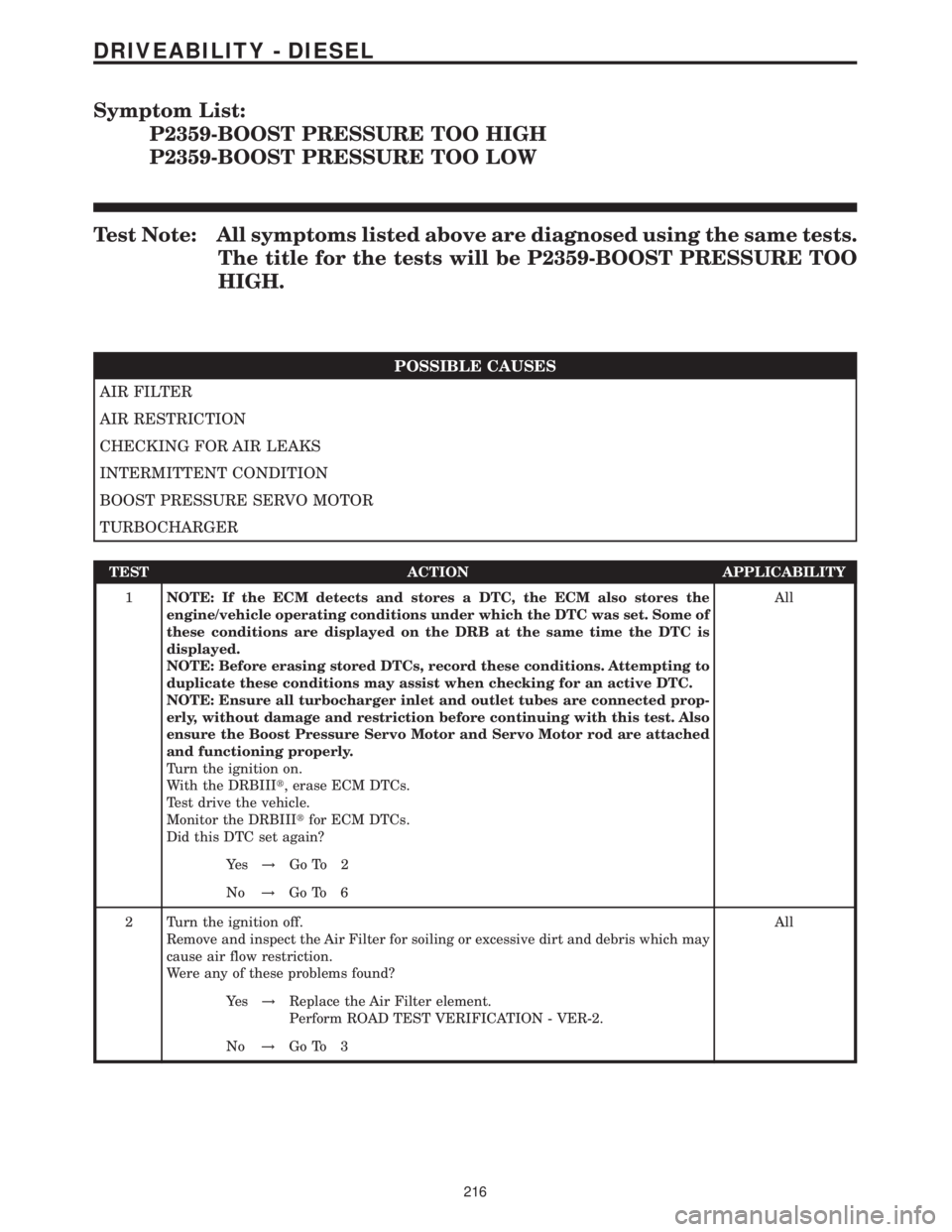
P2359-BOOST PRESSURE TOO HIGH
P2359-BOOST PRESSURE TOO LOW
Test Note: All symptoms listed above are diagnosed using the same tests.
The title for the tests will be P2359-BOOST PRESSURE TOO
HIGH.
POSSIBLE CAUSES
AIR FILTER
AIR RESTRICTION
CHECKING FOR AIR LEAKS
INTERMITTENT CONDITION
BOOST PRESSURE SERVO MOTOR
TURBOCHARGER
TEST ACTION APPLICABILITY
1NOTE: If the ECM detects and stores a DTC, the ECM also stores the
engine/vehicle operating conditions under which the DTC was set. Some of
these conditions are displayed on the DRB at the same time the DTC is
displayed.
NOTE: Before erasing stored DTCs, record these conditions. Attempting to
duplicate these conditions may assist when checking for an active DTC.
NOTE: Ensure all turbocharger inlet and outlet tubes are connected prop-
erly, without damage and restriction before continuing with this test. Also
ensure the Boost Pressure Servo Motor and Servo Motor rod are attached
and functioning properly.
Turn the ignition on.
With the DRBIIIt, erase ECM DTCs.
Test drive the vehicle.
Monitor the DRBIIItfor ECM DTCs.
Did this DTC set again?All
Ye s!Go To 2
No!Go To 6
2 Turn the ignition off.
Remove and inspect the Air Filter for soiling or excessive dirt and debris which may
cause air flow restriction.
Were any of these problems found?All
Ye s!Replace the Air Filter element.
Perform ROAD TEST VERIFICATION - VER-2.
No!Go To 3
216
DRIVEABILITY - DIESEL
Page 682 of 2305

ENGINE CONTROL MODULE C1 (OBD)CAV CIRCUIT FUNCTION
1 16BL FUEL INJECTOR NO. 1 HIGH-SIDE CONTROL
2 16BL/WT FUEL INJECTOR NO. 4 HIGH-SIDE CONTROL
3 16DG FUEL INJECTOR NO. 3 HIGH-SIDE CONTROL
4 20RD/WT FUEL PRESSURE SOLENOID 12 VOLT SUPPLY
8 18BL/GY FUEL TEMPERATURE SENSOR SIGNAL
10 20RD/YL ENGINE OIL SENSOR 5 VOLT SUPPLY
11 20GY/BL ENGINE OIL SENSOR SIGNAL
12 20BR/RD INTAKE PRESSURE SENSOR GROUND
13 20VT/DG INTAKE PRESSURE SENSOR SIGNAL
14 20BR/DG CAMSHAFT POSITION SENSOR GROUND
15 20DG/BK O2 1/1 PUMP CELL SIGNAL
20 18BK/YL WATER IN FUEL SENSOR SIGNAL
21 18BK/RD CRANKCASE HEATER SIGNAL
25 16BK FUEL INJECTOR NO. 2 HIGH-SIDE CONTROL
26 16BK/WT FUEL INJECTOR NO. 5 HIGH-SIDE CONTROL
28 18RD/BK FUEL QUANTITY SOLENOID 12 VOLT SUPPLY
31 20YL/BL MASS AIR FLOW SENSOR GROUND
32 18DG/BK FUEL TEMPERATURE SENSOR GROUND
35 20BR/BK SENSOR GROUND
36 20VT/RD INTAKE PRESSURE SENSOR 5 VOLT SUPPLY
37 20RD/BL CAMSHAFT POSITION SENSOR 5 VOLT SUPPLY
38 20YL/GY CAMSHAFT POSITION SENSOR SIGNAL
39 20GY O2 1/1 SENSOR CELL SIGNAL
40 20GY/WT O2 1/1 VIRTUAL GROUND
49 16BK/VT FUEL INJECTOR NO. 4 LOW-SIDE CONTROL
50 16BK/DG FUEL INJECTOR NO. 3 LOW-SIDE CONTROL
51 16BK/YL FUEL INJECTOR NO. 5 LOW-SIDE CONTROL
52 20BK/WT FUEL PRESSURE SOLENOID CONTROL
55 18BR WATER IN FUEL SENSOR GROUND
56 20BR/WT ENGINE COOLANT TEMPERATURE SENSOR GROUND
57 20DG/RD ENGINE COOLANT TEMPERATURE SENSOR SIGNAL
59 20DG/VT FUEL PRESSURE SENSOR SIGNAL
61 20BR/VT MASS AIR FLOW SENSOR 5 VOLT SUPPLY
62 20DG/YL O2 1/1 PUMP CELL CONTROL
72 20GY/BL O2 1/1 HEATER CONTROL
73 16BK/RD FUEL INJECTOR NO. 1 LOW-SIDE CONTROL
74 16BK/BL FUEL INJECTOR NO. 2 LOW-SIDE CONTROL
76 18BR/YL FUEL QUANTITY SOLENOID CONTROL
79 18BR/RD WATER IN FUEL SENSOR 12 VOLT SUPPLY
84 20BR/GY FUEL PRESSURE SENSOR GROUND
85 20YL/DG MASS AIR FLOW SENSOR SIGNAL
86 20RD/DG FUEL PRESSURE SENSOR 5 VOLT SUPPLY
87 20DG/WT CRANKSHAFT POSITION SENSOR SIGNAL NO. 1
88 20DG CRANKSHAFT POSITION SENSOR SIGNAL NO. 2
90 20DG/WT EGR VALVE CONTROL
91 18BK/BR CRANKCASE HEATER GROUND
93 16YL/DG BOOST PRESSURE SERVOMOTOR CONTROL
C
O
N
N
E
C
T
O
R
P
I
N
O
U
T
S
259
CONNECTOR PINOUTS
Page 717 of 2305
AXLE FLUID
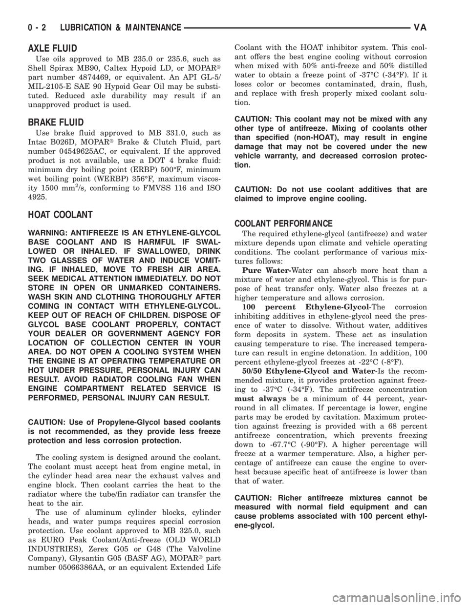
Use oils approved to MB 235.0 or 235.6, such as
Shell Spirax MB90, Caltex Hypoid LD, or MOPARt
part number 4874469, or equivalent. An API GL-5/
MIL-2105-E SAE 90 Hypoid Gear Oil may be substi-
tuted. Reduced axle durability may result if an
unapproved product is used.
BRAKE FLUID
Use brake fluid approved to MB 331.0, such as
Intac B026D, MOPARtBrake & Clutch Fluid, part
number 04549625AC, or equivalent. If the approved
product is not available, use a DOT 4 brake fluid:
minimum dry boiling point (ERBP) 500ÉF, minimum
wet boiling point (WERBP) 356ÉF, maximum viscos-
ity 1500 mm
2/s, conforming to FMVSS 116 and ISO
4925.
HOAT COOLANT
WARNING: ANTIFREEZE IS AN ETHYLENE-GLYCOL
BASE COOLANT AND IS HARMFUL IF SWAL-
LOWED OR INHALED. IF SWALLOWED, DRINK
TWO GLASSES OF WATER AND INDUCE VOMIT-
ING. IF INHALED, MOVE TO FRESH AIR AREA.
SEEK MEDICAL ATTENTION IMMEDIATELY. DO NOT
STORE IN OPEN OR UNMARKED CONTAINERS.
WASH SKIN AND CLOTHING THOROUGHLY AFTER
COMING IN CONTACT WITH ETHYLENE-GLYCOL.
KEEP OUT OF REACH OF CHILDREN. DISPOSE OF
GLYCOL BASE COOLANT PROPERLY, CONTACT
YOUR DEALER OR GOVERNMENT AGENCY FOR
LOCATION OF COLLECTION CENTER IN YOUR
AREA. DO NOT OPEN A COOLING SYSTEM WHEN
THE ENGINE IS AT OPERATING TEMPERATURE OR
HOT UNDER PRESSURE, PERSONAL INJURY CAN
RESULT. AVOID RADIATOR COOLING FAN WHEN
ENGINE COMPARTMENT RELATED SERVICE IS
PERFORMED, PERSONAL INJURY CAN RESULT.
CAUTION: Use of Propylene-Glycol based coolants
is not recommended, as they provide less freeze
protection and less corrosion protection.
The cooling system is designed around the coolant.
The coolant must accept heat from engine metal, in
the cylinder head area near the exhaust valves and
engine block. Then coolant carries the heat to the
radiator where the tube/fin radiator can transfer the
heat to the air.
The use of aluminum cylinder blocks, cylinder
heads, and water pumps requires special corrosion
protection. Use coolant approved to MB 325.0, such
as EURO Peak Coolant/Anti-freeze (OLD WORLD
INDUSTRIES), Zerex G05 or G48 (The Valvoline
Company), Glysantin G05 (BASF AG), MOPARtpart
number 05066386AA, or an equivalent Extended LifeCoolant with the HOAT inhibitor system. This cool-
ant offers the best engine cooling without corrosion
when mixed with 50% anti-freeze and 50% distilled
water to obtain a freeze point of -37ÉC (-34ÉF). If it
loses color or becomes contaminated, drain, flush,
and replace with fresh properly mixed coolant solu-
tion.
CAUTION: This coolant may not be mixed with any
other type of antifreeze. Mixing of coolants other
than specified (non-HOAT), may result in engine
damage that may not be covered under the new
vehicle warranty, and decreased corrosion protec-
tion.
CAUTION: Do not use coolant additives that are
claimed to improve engine cooling.
COOLANT PERFORMANCE
The required ethylene-glycol (antifreeze) and water
mixture depends upon climate and vehicle operating
conditions. The coolant performance of various mix-
tures follows:
Pure Water-Water can absorb more heat than a
mixture of water and ethylene-glycol. This is for pur-
pose of heat transfer only. Water also freezes at a
higher temperature and allows corrosion.
100 percent Ethylene-Glycol-The corrosion
inhibiting additives in ethylene-glycol need the pres-
ence of water to dissolve. Without water, additives
form deposits in system. These act as insulation
causing temperature to rise. The increased tempera-
ture can result in engine detonation. In addition, 100
percent ethylene-glycol freezes at -22ÉC (-8ÉF).
50/50 Ethylene-Glycol and Water-Is the recom-
mended mixture, it provides protection against freez-
ing to -37ÉC (-34ÉF). The antifreeze concentration
must alwaysbe a minimum of 44 percent, year-
round in all climates. If percentage is lower, engine
parts may be eroded by cavitation. Maximum protec-
tion against freezing is provided with a 68 percent
antifreeze concentration, which prevents freezing
down to -67.7ÉC (-90ÉF). A higher percentage will
freeze at a warmer temperature. Also, a higher per-
centage of antifreeze can cause the engine to over-
heat because specific heat of antifreeze is lower than
that of water.
CAUTION: Richer antifreeze mixtures cannot be
measured with normal field equipment and can
cause problems associated with 100 percent ethyl-
ene-glycol.
0 - 2 LUBRICATION & MAINTENANCEVA
Page 723 of 2305
effect panels. If necessary, remove the wheels from
the lifted end of the vehicle and lower the vehicle
closer to the ground, to increase the ground clearance
at the opposite end of the vehicle. Install lug nuts on
wheel attaching studs to retain brake drums.
RAMP ANGLE
If a vehicle with flat-bed towing equipment is used,
the approach ramp angle should not exceed 15
degrees.
TOWING WHEN KEYS ARE NOT AVAILABLE
When the vehicle is locked and keys are not avail-
able, use a flat bed hauler. A Wheel-lift or Sling-type
device can be used provided all the wheels are lifted
off the ground using tow dollies.
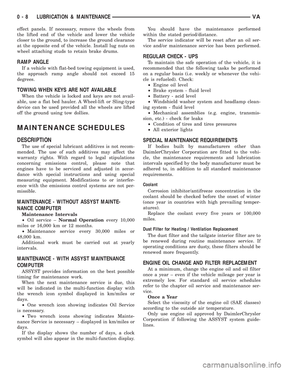
MAINTENANCE SCHEDULES
DESCRIPTION
The use of special lubricant additives is not recom-
mended. The use of such additives may affect the
warranty rights. With regard to legal stipulations
concerning emissions control, please note that
engines have to be serviced and adjusted in accor-
dance with special instructions and using special
measuring equipment. Modifications to or interfer-
ence with the emissions control systems are not per-
missible.
MAINTENANCE - WITHOUT ASSYST MAINTE-
NANCE COMPUTER
Maintenance Intervals
²Oil service ±Normal Operationevery 10,000
miles or 16,000 km or 12 months.
²Maintenance service every 30,000 miles or
48,000 km.
Additional work must be carried out at yearly
intervals.
MAINTENANCE - WITH ASSYST MAINTENANCE
COMPUTER
ASSYST provides information on the best possible
timing for maintenance work.
When the next maintenance service is due, this
will be indicated in the multi-function display with
the wrench icon symbol displayed in km/miles or
days.
²One wrench icon showing indicates Oil Service
is necessary.
²Two wrench icons showing indicates Mainte-
nance Service is necessary ± displayed in km/miles or
days.
If the display shows the number of days, a clock
symbol will also appear in the multi-function display.You should have the maintenance performed
within the stated period/distance.
The service indicator will be reset after an oil ser-
vice and/or maintenance service has been performed.
REGULAR CHECK - UPS
To maintain the safe operation of the vehicle, it is
recommended that the following tasks be performed
on a regular basis (i.e. weekly or whenever the vehi-
cle is refueled). Check:
²Engine oil level
²Brake system - fluid level
²Battery - acid level
²Windshield washer system and headlamp clean-
ing system - fluid level
²Mechanical assemblies (e.g. engine, transmis-
sion, etc.) - check for leaks
²Condition of tires and tires pressures
²All exterior lights
SPECIAL MAINTENANCE REQUIREMENTS
If bodies built by manufacturers other than
DaimlerChrysler Corporation are fitted to the vehi-
cle, the maintenance requirements and lubrication
intervals specified by the body manufacturer must be
adhered to, in addition to all standard maintenance
requirements.
Coolant
Corrosion inhibitor/antifreeze concentration in the
coolant should be checked before the onset of winter
(once year in countries with high prevailing temper-
atures).
Replace the coolant every five years or 100,000
miles.
Dust Filter for Heating / Ventilation Replacement
The dust filter and the tailgate interior filter are to
be renewed during routine maintenance service. If
operating conditions are dusty, these filters should be
renewed more frequently.
ENGINE OIL CHANGE AND FILTER REPLACEMENT
At a minimum, change the engine oil and oil filter
once a year ± even if the vehicle mileage per year is
extremely low. For standard oil service schedules
refer to the chapter oil service and maintenance ser-
vice.
Once a Year
Select the viscosity of the engine oil (SAE classes)
according to the outside air temperature.
Only use engine oil approved by DaimlerChrysler
Corporation if following the ASSYST system guide-
lines.
0 - 8 LUBRICATION & MAINTENANCEVA