2006 MERCEDES-BENZ SPRINTER low oil pressure
[x] Cancel search: low oil pressurePage 1578 of 2305
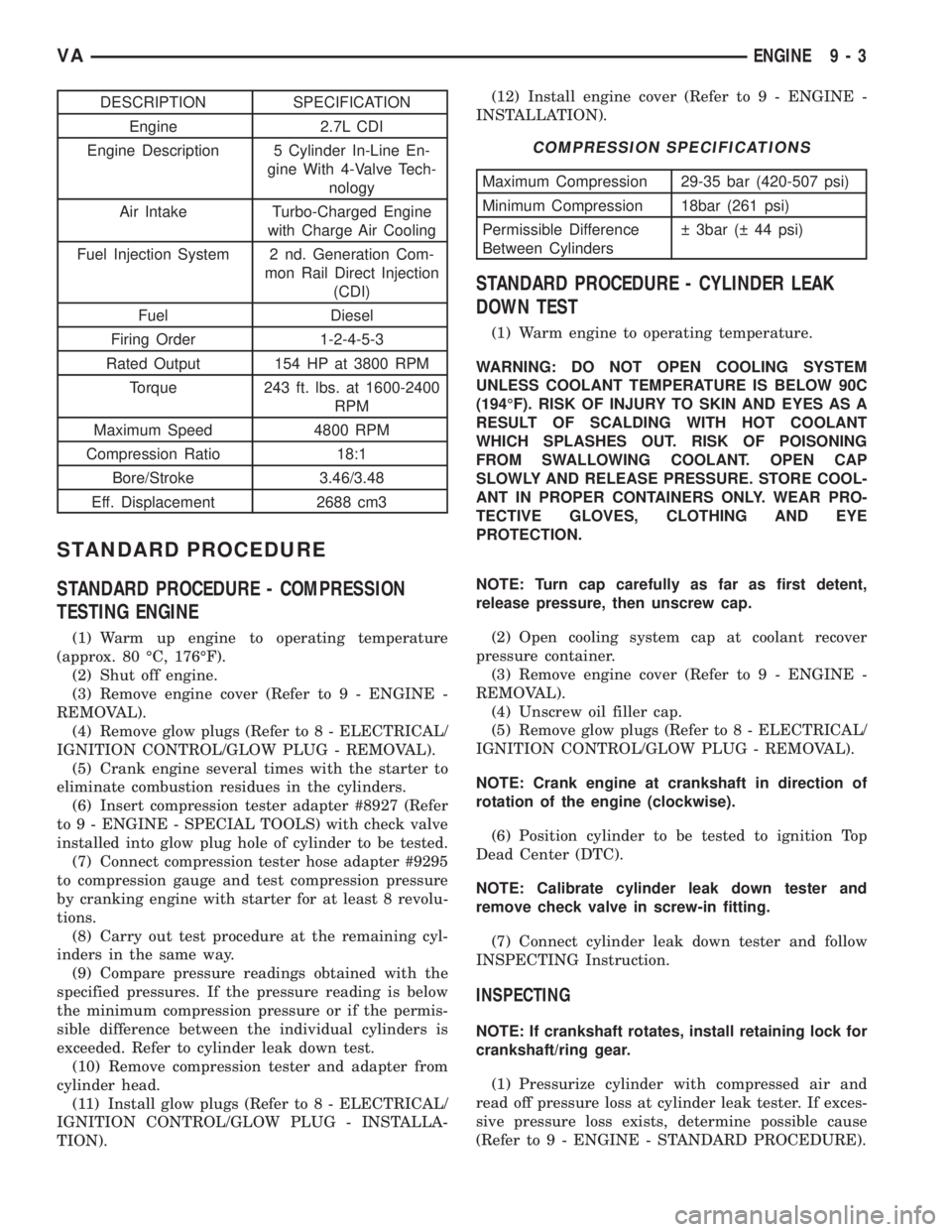
DESCRIPTION SPECIFICATION
Engine 2.7L CDI
Engine Description 5 Cylinder In-Line En-
gine With 4-Valve Tech-
nology
Air Intake Turbo-Charged Engine
with Charge Air Cooling
Fuel Injection System 2 nd. Generation Com-
mon Rail Direct Injection
(CDI)
Fuel Diesel
Firing Order 1-2-4-5-3
Rated Output 154 HP at 3800 RPM
Torque 243 ft. lbs. at 1600-2400
RPM
Maximum Speed 4800 RPM
Compression Ratio 18:1
Bore/Stroke 3.46/3.48
Eff. Displacement 2688 cm3
STANDARD PROCEDURE
STANDARD PROCEDURE - COMPRESSION
TESTING ENGINE
(1) Warm up engine to operating temperature
(approx. 80 ÉC, 176ÉF).
(2) Shut off engine.
(3) Remove engine cover (Refer to 9 - ENGINE -
REMOVAL).
(4) Remove glow plugs (Refer to 8 - ELECTRICAL/
IGNITION CONTROL/GLOW PLUG - REMOVAL).
(5) Crank engine several times with the starter to
eliminate combustion residues in the cylinders.
(6) Insert compression tester adapter #8927 (Refer
to 9 - ENGINE - SPECIAL TOOLS) with check valve
installed into glow plug hole of cylinder to be tested.
(7) Connect compression tester hose adapter #9295
to compression gauge and test compression pressure
by cranking engine with starter for at least 8 revolu-
tions.
(8) Carry out test procedure at the remaining cyl-
inders in the same way.
(9) Compare pressure readings obtained with the
specified pressures. If the pressure reading is below
the minimum compression pressure or if the permis-
sible difference between the individual cylinders is
exceeded. Refer to cylinder leak down test.
(10) Remove compression tester and adapter from
cylinder head.
(11) Install glow plugs (Refer to 8 - ELECTRICAL/
IGNITION CONTROL/GLOW PLUG - INSTALLA-
TION).(12) Install engine cover (Refer to 9 - ENGINE -
INSTALLATION).
COMPRESSION SPECIFICATIONS
Maximum Compression 29-35 bar (420-507 psi)
Minimum Compression 18bar (261 psi)
Permissible Difference
Between Cylinders 3bar ( 44 psi)
STANDARD PROCEDURE - CYLINDER LEAK
DOWN TEST
(1) Warm engine to operating temperature.
WARNING: DO NOT OPEN COOLING SYSTEM
UNLESS COOLANT TEMPERATURE IS BELOW 90C
(194ÉF). RISK OF INJURY TO SKIN AND EYES AS A
RESULT OF SCALDING WITH HOT COOLANT
WHICH SPLASHES OUT. RISK OF POISONING
FROM SWALLOWING COOLANT. OPEN CAP
SLOWLY AND RELEASE PRESSURE. STORE COOL-
ANT IN PROPER CONTAINERS ONLY. WEAR PRO-
TECTIVE GLOVES, CLOTHING AND EYE
PROTECTION.
NOTE: Turn cap carefully as far as first detent,
release pressure, then unscrew cap.
(2) Open cooling system cap at coolant recover
pressure container.
(3) Remove engine cover (Refer to 9 - ENGINE -
REMOVAL).
(4) Unscrew oil filler cap.
(5) Remove glow plugs (Refer to 8 - ELECTRICAL/
IGNITION CONTROL/GLOW PLUG - REMOVAL).
NOTE: Crank engine at crankshaft in direction of
rotation of the engine (clockwise).
(6) Position cylinder to be tested to ignition Top
Dead Center (DTC).
NOTE: Calibrate cylinder leak down tester and
remove check valve in screw-in fitting.
(7) Connect cylinder leak down tester and follow
INSPECTING Instruction.
INSPECTING
NOTE: If crankshaft rotates, install retaining lock for
crankshaft/ring gear.
(1) Pressurize cylinder with compressed air and
read off pressure loss at cylinder leak tester. If exces-
sive pressure loss exists, determine possible cause
(Refer to 9 - ENGINE - STANDARD PROCEDURE).
VAENGINE 9 - 3
Page 1579 of 2305
NOTE: If the retaining lock is installed, remove it,
rotate engine and install lock once again.
(2) Carry out test of other cylinders in the firing
order of engine.
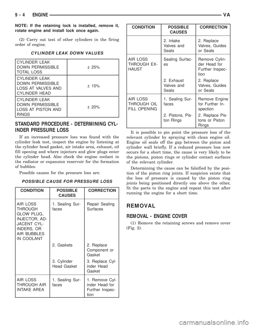
CYLINDER LEAK DOWN VALUES
CYLINDER LEAK
DOWN PERMISSIBLE
TOTAL LOSS 25%
CYLINDER LEAK
DOWN PERMISSIBLE
LOSS AT VALVES AND
CYLINDER HEAD 10%
CYLINDER LEAK
DOWN PERMISSIBLE
LOSS AT PISTON AND
RINGS 20%
STANDARD PROCEDURE - DETERMINING CYL-
INDER PRESSURE LOSS
If an increased pressure loss was found with the
cylinder leak test, inspect the engine by listening at
the cylinder head gasket, air intake area, exhaust, oil
fill opening and where injectors and glow plugs enter
the cylinder head. Also check the engine coolant in
the radiator or expansion reservoir for the formation
of bubbles.
Possible causes for the pressure loss are:
POSSIBLE CAUSE FOR PRESSURE LOSS
CONDITION POSSIBLE
CAUSESCORRECTION
AIR LOSS
THROUGH
GLOW PLUG,
INJECTOR, AD-
JACENT CYL-
INDERS, OR
AIR BUBBLES
IN COOLANT1. Sealing Sur-
facesRepair Sealing
Surfaces
2. Gaskets 2. Replace
Component or
Gasket
3. Cylinder
Head Gasket3. Replace Cyl-
inder Head
Gasket
AIR LOSS
THROUGH AIR
INTAKE AREA1. Sealing Sur-
faces1. Remove Cyl-
inder Head for
Further Inspec-
tion
CONDITION POSSIBLE
CAUSESCORRECTION
2. Intake
Valves and
Seats2. Replace
Valves, Guides
or Seats
AIR LOSS
THROUGH EX-
HAUSTSealing Surfac-
esRemove Cylin-
der Head for
Further Inspec-
tion
2. Exhaust
Valves and
Seats2. Replace
Valves, Guides
or Seats
AIR LOSS
THROUGH OIL
FILL OPENING1. Sealing Sur-
facesRemove Engine
for Further In-
spection
2. Pistons, Pis-
ton Rings2. Replace Pis-
tons or Piston
Rings
It is possible to pin point the pressure loss of the
relevant cylinder by spraying with clean engine oil.
Engine oil seals off the gap between the piston and
cylinder wall briefly. If a reduced pressure loss now
occurs for a short time, the cause is very likely to be
the pistons, piston rings or cylinder contact surfaces
of the relevant cylinder.
Determining the cause can be falsified by the posi-
tion of the piston ring joints. If suspicion exists that
the loss of pressure is caused by the piston ring
joints being positioned directly one above the other,
fit the parts to the engine and repeat this test after
running the engine for a short time.
REMOVAL
REMOVAL - ENGINE COVER
(1) Remove the retaining screws and remove cover
(Fig. 2).
9 - 4 ENGINEVA
Page 1581 of 2305
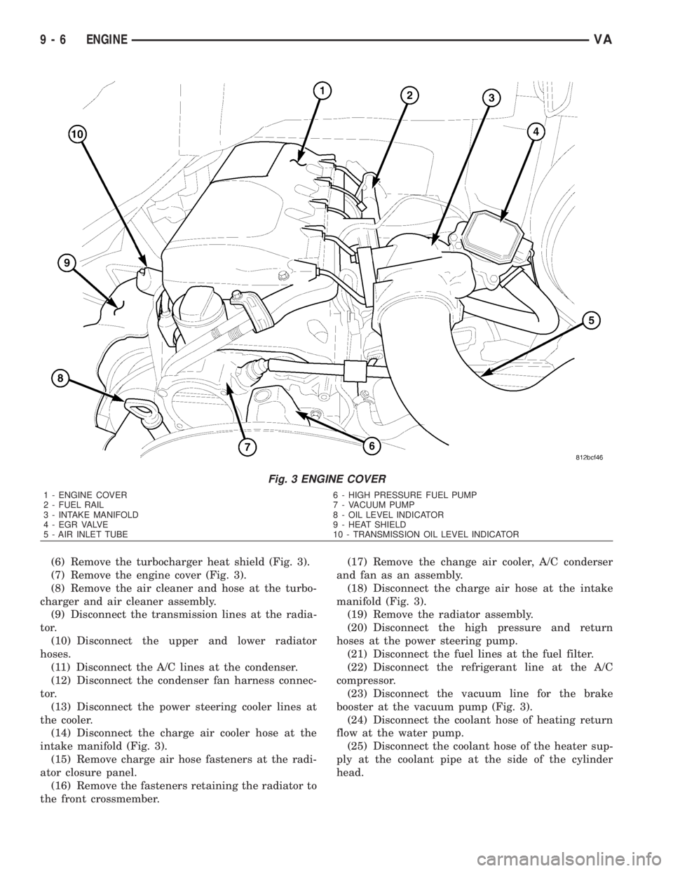
(6) Remove the turbocharger heat shield (Fig. 3).
(7) Remove the engine cover (Fig. 3).
(8) Remove the air cleaner and hose at the turbo-
charger and air cleaner assembly.
(9) Disconnect the transmission lines at the radia-
tor.
(10) Disconnect the upper and lower radiator
hoses.
(11) Disconnect the A/C lines at the condenser.
(12) Disconnect the condenser fan harness connec-
tor.
(13) Disconnect the power steering cooler lines at
the cooler.
(14) Disconnect the charge air cooler hose at the
intake manifold (Fig. 3).
(15) Remove charge air hose fasteners at the radi-
ator closure panel.
(16) Remove the fasteners retaining the radiator to
the front crossmember.(17) Remove the change air cooler, A/C conderser
and fan as an assembly.
(18) Disconnect the charge air hose at the intake
manifold (Fig. 3).
(19) Remove the radiator assembly.
(20) Disconnect the high pressure and return
hoses at the power steering pump.
(21) Disconnect the fuel lines at the fuel filter.
(22) Disconnect the refrigerant line at the A/C
compressor.
(23) Disconnect the vacuum line for the brake
booster at the vacuum pump (Fig. 3).
(24) Disconnect the coolant hose of heating return
flow at the water pump.
(25) Disconnect the coolant hose of the heater sup-
ply at the coolant pipe at the side of the cylinder
head.
Fig. 3 ENGINE COVER
1 - ENGINE COVER 6 - HIGH PRESSURE FUEL PUMP
2 - FUEL RAIL 7 - VACUUM PUMP
3 - INTAKE MANIFOLD 8 - OIL LEVEL INDICATOR
4 - EGR VALVE 9 - HEAT SHIELD
5 - AIR INLET TUBE 10 - TRANSMISSION OIL LEVEL INDICATOR
9 - 6 ENGINEVA
Page 1585 of 2305
(11) Install the torque converter access plate. Refer
to (Refer to 21 - TRANSMISSION/TRANSAXLE/AU-
TOMATIC - NAG1 - INSTALLATION) for correct
sequence and torque specification.
(12) Install the transmission cooler lines to trans-
mission. (Refer to 21 - TRANSMISSION/TRANS-
AXLE/AUTOMATIC - NAG1 - INSTALLATION) for
correct sequence and torque specification.
(13) Connect the engine valley drain hose to the
transmission (Fig. 5).
(14) Install transmission electrical connector and
shifter hardware. Refer to (Refer to 21 - TRANSMIS-
SION/TRANSAXLE/AUTOMATIC - NAG1 - INSTAL-
LATION) for correct sequence and torque
specification.
(15) Install the steering gear and tighten in two
stages. 25 N´m (18.5 lbs. ft.), then 45 N´m (33 lbs. ft.)
plus 90É.
(16) Install the starter.
(17) Connect the ground strap (left side).
(18) Align and install the exhaust and bracket
(Refer to 11 - EXHAUST SYSTEM/EXHAUST PIPE -
INSTALLATION).
(19) Lower the vehicle.
(20) Install the lower heater housing and filter.
(21) Install the air inlet hose, CCV breather and
CCV heater at the turbocharger (Fig. 4).
(22) Connect the coolant supply and return hoses.
(23) Connect the brake booster vacuum hose at the
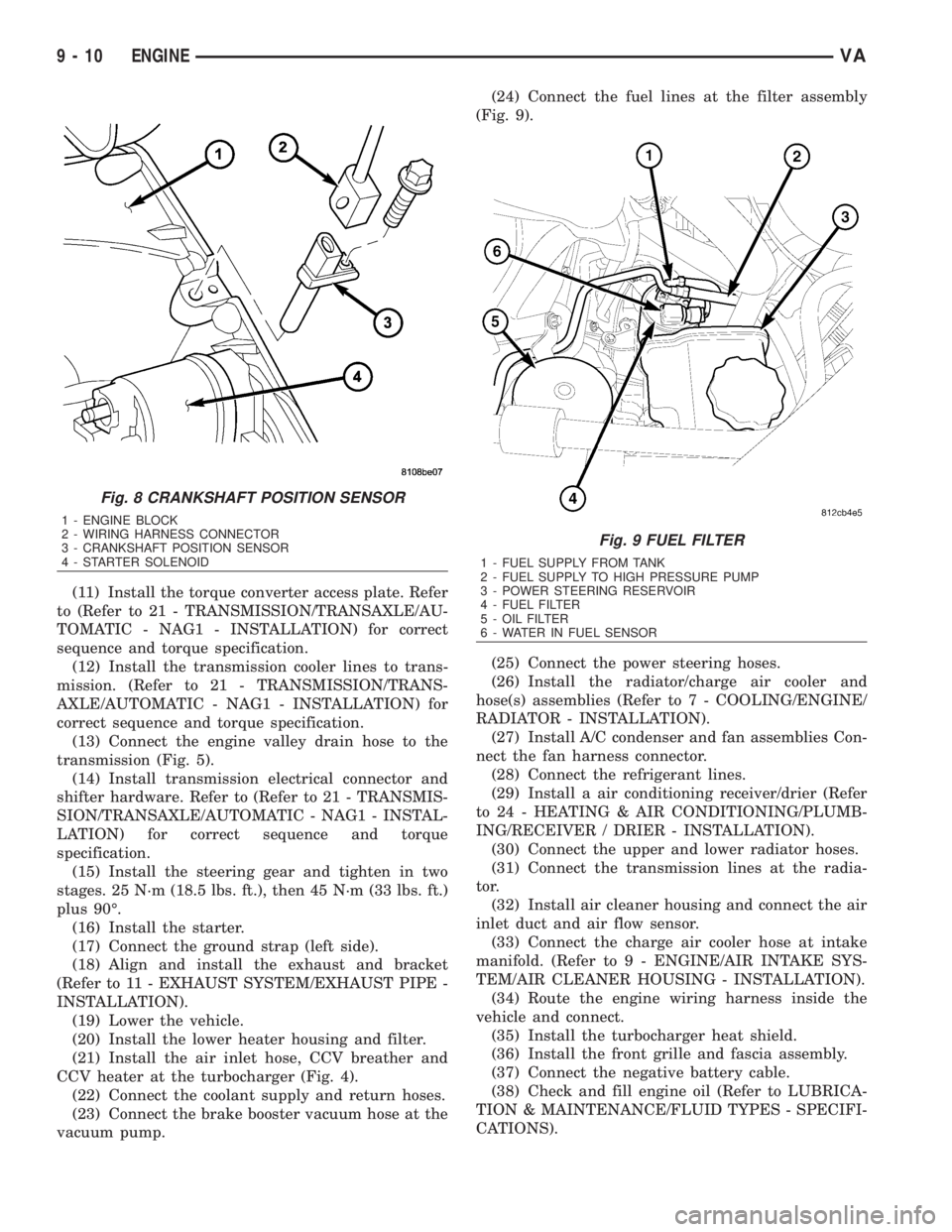
vacuum pump.(24) Connect the fuel lines at the filter assembly
(Fig. 9).
(25) Connect the power steering hoses.
(26) Install the radiator/charge air cooler and
hose(s) assemblies (Refer to 7 - COOLING/ENGINE/
RADIATOR - INSTALLATION).
(27) Install A/C condenser and fan assemblies Con-
nect the fan harness connector.
(28) Connect the refrigerant lines.
(29) Install a air conditioning receiver/drier (Refer
to 24 - HEATING & AIR CONDITIONING/PLUMB-
ING/RECEIVER / DRIER - INSTALLATION).
(30) Connect the upper and lower radiator hoses.
(31) Connect the transmission lines at the radia-
tor.
(32) Install air cleaner housing and connect the air
inlet duct and air flow sensor.
(33) Connect the charge air cooler hose at intake
manifold. (Refer to 9 - ENGINE/AIR INTAKE SYS-
TEM/AIR CLEANER HOUSING - INSTALLATION).
(34) Route the engine wiring harness inside the
vehicle and connect.
(35) Install the turbocharger heat shield.
(36) Install the front grille and fascia assembly.
(37) Connect the negative battery cable.
(38) Check and fill engine oil (Refer to LUBRICA-
TION & MAINTENANCE/FLUID TYPES - SPECIFI-
CATIONS).
Fig. 8 CRANKSHAFT POSITION SENSOR
1 - ENGINE BLOCK
2 - WIRING HARNESS CONNECTOR
3 - CRANKSHAFT POSITION SENSOR
4 - STARTER SOLENOID
Fig. 9 FUEL FILTER
1 - FUEL SUPPLY FROM TANK
2 - FUEL SUPPLY TO HIGH PRESSURE PUMP
3 - POWER STEERING RESERVOIR
4 - FUEL FILTER
5 - OIL FILTER
6 - WATER IN FUEL SENSOR
9 - 10 ENGINEVA
Page 1599 of 2305
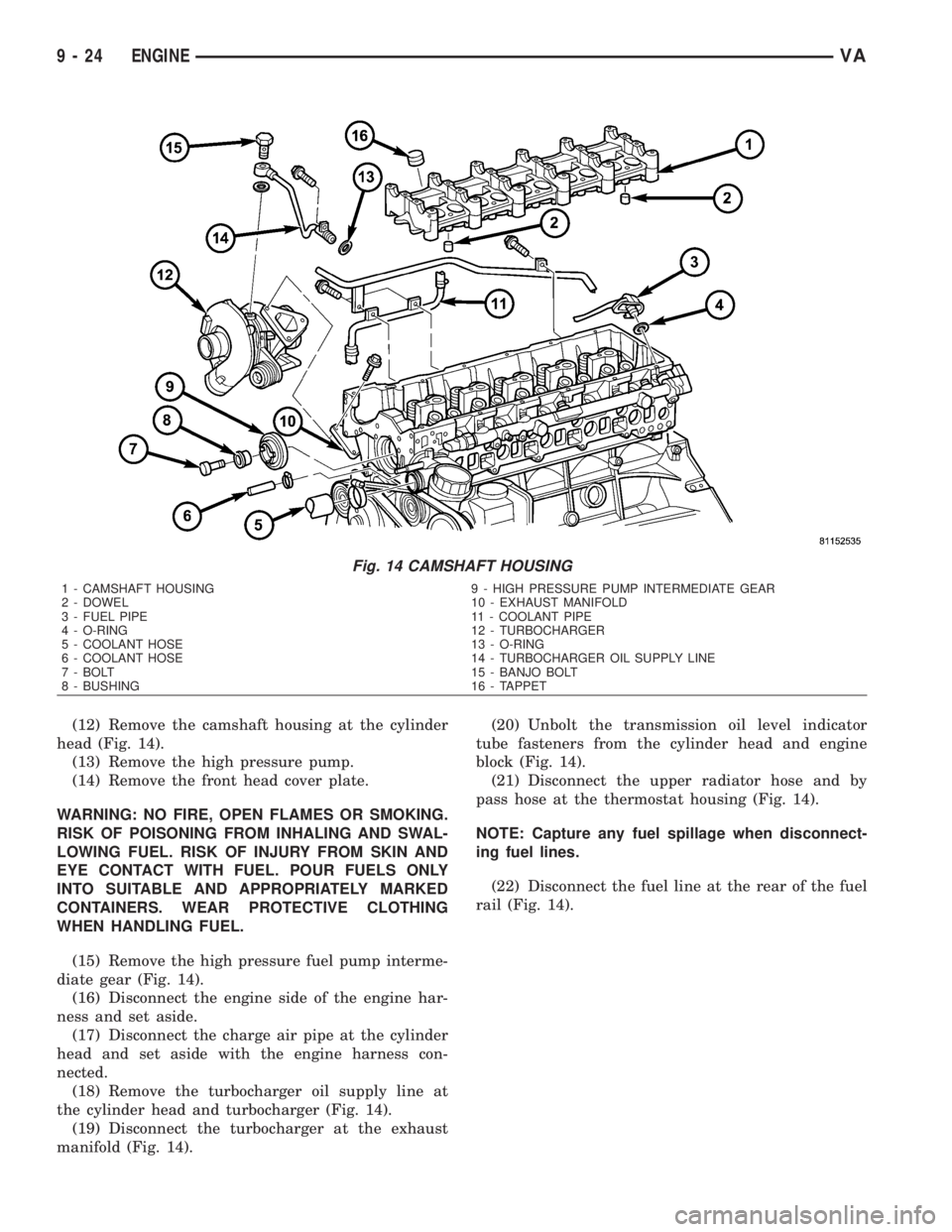
(12) Remove the camshaft housing at the cylinder
head (Fig. 14).
(13) Remove the high pressure pump.
(14) Remove the front head cover plate.
WARNING: NO FIRE, OPEN FLAMES OR SMOKING.
RISK OF POISONING FROM INHALING AND SWAL-
LOWING FUEL. RISK OF INJURY FROM SKIN AND
EYE CONTACT WITH FUEL. POUR FUELS ONLY
INTO SUITABLE AND APPROPRIATELY MARKED
CONTAINERS. WEAR PROTECTIVE CLOTHING
WHEN HANDLING FUEL.
(15) Remove the high pressure fuel pump interme-
diate gear (Fig. 14).
(16) Disconnect the engine side of the engine har-
ness and set aside.
(17) Disconnect the charge air pipe at the cylinder
head and set aside with the engine harness con-
nected.
(18) Remove the turbocharger oil supply line at
the cylinder head and turbocharger (Fig. 14).
(19) Disconnect the turbocharger at the exhaust
manifold (Fig. 14).(20) Unbolt the transmission oil level indicator
tube fasteners from the cylinder head and engine
block (Fig. 14).
(21) Disconnect the upper radiator hose and by
pass hose at the thermostat housing (Fig. 14).
NOTE: Capture any fuel spillage when disconnect-
ing fuel lines.
(22) Disconnect the fuel line at the rear of the fuel
rail (Fig. 14).
Fig. 14 CAMSHAFT HOUSING
1 - CAMSHAFT HOUSING 9 - HIGH PRESSURE PUMP INTERMEDIATE GEAR
2 - DOWEL 10 - EXHAUST MANIFOLD
3 - FUEL PIPE 11 - COOLANT PIPE
4 - O-RING 12 - TURBOCHARGER
5 - COOLANT HOSE 13 - O-RING
6 - COOLANT HOSE 14 - TURBOCHARGER OIL SUPPLY LINE
7 - BOLT 15 - BANJO BOLT
8 - BUSHING 16 - TAPPET
9 - 24 ENGINEVA
Page 1602 of 2305
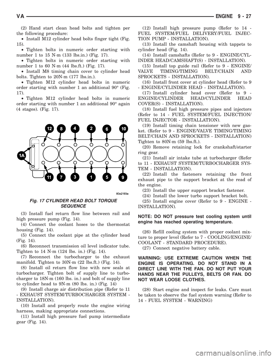
(2) Hand start clean head bolts and tighten per
the following procedure:
²Install M12 cylinder head bolts finger tight (Fig.
15).
²Tighten bolts in numeric order starting with
number 1 to 15 N´m (133 lbs.in.) (Fig. 17).
²Tighten bolts in numeric order starting with
number 1 to 60 N´m (44 lbs.ft.) (Fig. 17).
²Install M8 timing chain cover to cylinder head
bolts. Tighten to 20N´m (177 lbs.in.).
²Tighten M12 cylinder head bolts in numeric
order starting with number 1 an additional 90É (Fig.
17).
²Tighten M12 cylinder head bolts in numeric
order starting with number 1 an additional 90É again
(4 stages). (Fig. 17).
(3) Install fuel return flow line between rail and
high pressure pump (Fig. 14).
(4) Connect the coolant hoses to the thermostat
housing (Fig. 14).
(5) Connect the coolant pipe at the cylinder head
(Fig. 14).
(6) Reconnect transmission oil level indicator tube.
Tighten to 14 N´m (124 lbs. in.) (Fig. 14).
(7) Reconnect the turbocharger to the exhaust
manifold. Tighten to 30N´m (22 lbs.ft.) (Fig. 14).
(8) Install oil return flow line with new seals at
turbocharger. Tighten bolt of supply line to turbo-
charger to 18N´m (160 lbs. in.) and bolt of supply line
to cylinder head to 9N´m (80 lbs. in.) (Fig. 14)
(9) Install charge air distribution pipe (Refer to 11
- EXHAUST SYSTEM/TURBOCHARGER SYSTEM -
INSTALLATION).
(10) Install and properly route the engine wiring
harness, making appropriate connections.
(11) Install high pressure fuel pump intermediate
gear (Fig. 14).(12) Install high pressure pump (Refer to 14 -
FUEL SYSTEM/FUEL DELIVERY/FUEL INJEC-
TION PUMP - INSTALLATION).
(13) Install the camshaft housing with tappets to
cylinder head (Fig. 14).
(14) Install camshafts (Refer to 9 - ENGINE/CYL-
INDER HEAD/CAMSHAFT(S) - INSTALLATION).
(15) Install top guide rail (Refer to 9 - ENGINE/
VALVE TIMING/TIMING BELT/CHAIN AND
SPROCKETS - INSTALLATION).
(16) Install front cover at cylinder head (Refer to 9
- ENGINE/CYLINDER HEAD - INSTALLATION).
(17) Install cylinder head cover (Refer to 9 -
ENGINE/CYLINDER HEAD/CYLINDER HEAD
COVER(S) - INSTALLATION).
(18) Install fuel high pressure pipes and injectors
(Refer to 14 - FUEL SYSTEM/FUEL INJECTION/
FUEL INJECTOR - INSTALLATION).
(19) Install timing chain tensioner with new gas-
ket. (Refer to 9 - ENGINE/VALVE TIMING/TIMING
BELT/CHAIN AND SPROCKETS - INSTALLATION)
Tighten to 80N´m (59 lbs.ft.).
(20) Remove retaining lock for crankshaft/starter
ring gear.
(21) Install air intake tube at turbocharger (Refer
to 11 - EXHAUST SYSTEM/TURBOCHARGER SYS-
TEM - INSTALLATION).
(22) Install the fasteners retaining the front
exhaust pipe to the support bracket at the read of
the engine.
(23) Install the upper support bracket fastener.
(24) Install the lower turbo support bracket bolt.
(25) Install engine cover (Refer to 9 - ENGINE -
INSTALLATION).
NOTE: DO NOT pressure test cooling system until
engine has reached operating temperature.
(26) Refill cooling system with proper coolant mix-
ture to proper level (Refer to 7 - COOLING/ENGINE/
COOLANT - STANDARD PROCEDURE).
(27) Connect negative battery cable.
WARNING: USE EXTREME CAUTION WHEN THE
ENGINE IS OPERATING. DO NOT STAND IN A
DIRECT LINE WITH THE FAN. DO NOT PUT YOUR
HANDS NEAR THE PULLEYS, BELTS OR FAN. DO
NOT WEAR LOOSE CLOTHES.
(28) Start engine and inspect for leaks. Care must
be taken to observe the fuel system warning (Refer to
14 - FUEL SYSTEM - WARNING)
Fig. 17 CYLINDER HEAD BOLT TORQUE
SEQUENCE
VAENGINE 9 - 27
Page 1606 of 2305
(7) Remove timing chain tensioner (Refer to 9 -
ENGINE/VALVE TIMING/TIMING BELT/CHAIN
AND SPROCKETS - REMOVAL).
NOTE: The lower portion of the cylinder head front
cover is sealed with RTV sealant. Carefully tug front
cover after bolt removal to loosen from cylinder
head.
(8) Remove cylinder head front cover (Refer to 9 -
ENGINE/CYLINDER HEAD - REMOVAL).
(9) Remove top side rail (Refer to 9 - ENGINE/
CYLINDER HEAD - REMOVAL).CAUTION: For all work in which the crankshaft
should not rotate, secure camshaft gear to timing
chain.
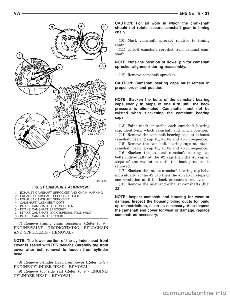
(10) Mark camshaft sprocket relative to timing
chain.
(11) Unbolt camshaft sprocket from exhaust cam-
shaft.
NOTE: Note the position of dowel pin for camshaft
sprocket alignment during reassembly.
(12) Remove camshaft sprocket.
CAUTION: Camshaft bearing caps must remain in
proper order and position.
NOTE: Slacken the bolts of the camshaft bearing
caps evenly in steps of one turn until the back
pressure is eliminated. Camshafts must not be
twisted when slackening the camshaft bearing
caps.
(13) Paint mark or scribe each camshaft bearing
cap, identifying which camshaft and which position.
(14) Remove the camshaft bearing caps at exhaust
camshaft bearing cap #1, #3,#4 and #6 in sequence.
(15) Remove the camshaft bearing caps at intake
camshaft bearing cap #1, #3,#4 and #6 in sequence.
(16) Slacken the exhaust camshaft bearing cap
bolts individually at the #2 cap then the #5 cap in
steps of one revolution until the back pressure is
removed.
(17) Slacken the intake camshaft bearing cap bolts
individually at the #2 cap then the #5 cap in steps of
one revolution until the back pressure is removed.
(18) Remove the inlet and exhaust camshafts (Fig.
22).
NOTE: Inspect camshaft and housing for wear or
damage. Inspect the housing oiling ducts for build
up or restrictions, clean as necessary. Also inspect
the camshaft end cover for wear or damage, replace
camshaft as necessary.
Fig. 21 CAMSHAFT ALIGNMENT
1 - EXHAUST CAMSHAFT SPROCKET AND CHAIN MARKING
2 - EXHAUST CAMSHAFT SPROCKET BOLTS
3 - EXHAUST CAMSHAFT SPROCKET
4 - CAMSHAFT ALIGNMENT DOTS
5 - INTAKE CAMSHAFT LOCK POSITION
6 - INTAKE CAMSHAFT SPROCKET
7 - INTAKE CAMSHAFT LOCK (SPECIAL TOOL #8929)
8 - INTAKE CAMSHAFT SPROCKET
VAENGINE 9 - 31
Page 1608 of 2305
NOTE: The piston of cylinder #1 must be positioned
at ignition TDC when the inlet camshaft is locked.
(8) Insert locking pin through the first camshaft
bearing cap into the whole in the camshaft sprocket.
NOTE: Do Not use old camshaft sprocket bolts.
(9) Fit camshaft sprocket with timing chain fitted
on, onto exhaust camshaft paying attention to posi-
tion of dowel pin. Tighten bolt to 18N´m (159 lbs.in.).
(10) Install timing chain tensioner (Refer to 9 -
ENGINE/VALVE TIMING/TIMING BELT/CHAIN
AND SPROCKETS - INSTALLATION).
(11) Inspect/Set basic position of camshafts (Refer
to 9 - ENGINE/CYLINDER HEAD/CAMSHAFT(S) -
STANDARD PROCEDURE).
(12) Insert slide rail and bolt the driver into the
inlet camshaft. Tighten bolt driver to 50N´m (37 lbs.
in.).
(13) Install front cover at cylinder head.
(14) Install cylinder head cover (Refer to 9 -
ENGINE/CYLINDER HEAD/CYLINDER HEAD
COVER(S) - INSTALLATION).
NOTE: Refer to the appropriate injector servicing
procedures for cleaning of injectors and recesses.
(15) Clean and install injectors (Refer to 14 -
FUEL SYSTEM/FUEL INJECTION/FUEL INJEC-
TOR - STANDARD PROCEDURE), (Refer to 14 -
FUEL SYSTEM/FUEL INJECTION/FUEL INJEC-
TOR - INSTALLATION).
(16) Reconnect negative battery cable.WARNING: (Refer to 14 - FUEL SYSTEM - WARN-
ING).
WARNING: USE EXTREME CAUTION WHEN THE
ENGINE IS OPERATING. DO NOT STAND IN A
DIRECT LINE WITH THE FAN. DO NOT PUT YOUR
HANDS NEAR THE PULLEYS, BELTS OR FAN. DO
NOT WEAR LOOSE CLOTHING.
(17) Start engine and inspect for leaks.Care must
be taken to observe the fuel system warning (Refer to
14 - FUEL SYSTEM - WARNING).
(18) Install engine cover (Refer to 9 - ENGINE
COVER - INSTALLATION).
CYLINDER HEAD COVER(S)
REMOVAL
(1) Disconnect negative battery cable.
(2) Disconnect the air inlet and set aside.
(3) Detach hose from oil separator.
(4) Disconnect the camshaft position sensor.
(5) Disconnect fuel injector and glow plug harness
and set aside.
(6) Remove fuel high pressure pipes and injectors
(Refer to 14 - FUEL SYSTEM/FUEL INJECTION/
FUEL INJECTOR - REMOVAL).
(7) Disconnect the out let line.
(8) Remove cylinder head cover retaining bolts and
remove cover (Fig. 25).
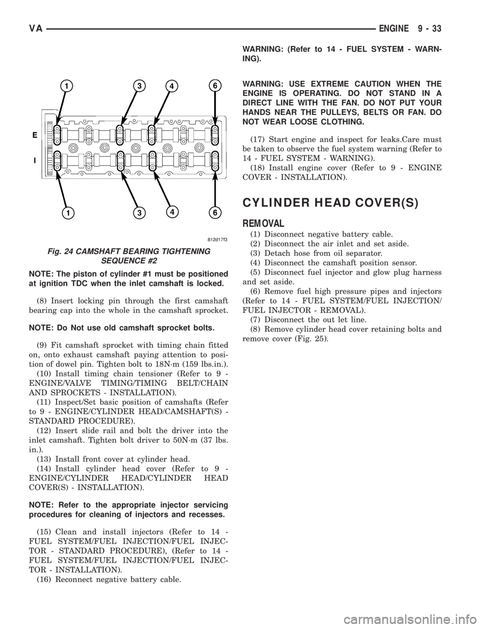
Fig. 24 CAMSHAFT BEARING TIGHTENING
SEQUENCE #2
VAENGINE 9 - 33