2006 MERCEDES-BENZ SPRINTER turn signal
[x] Cancel search: turn signalPage 1514 of 2305
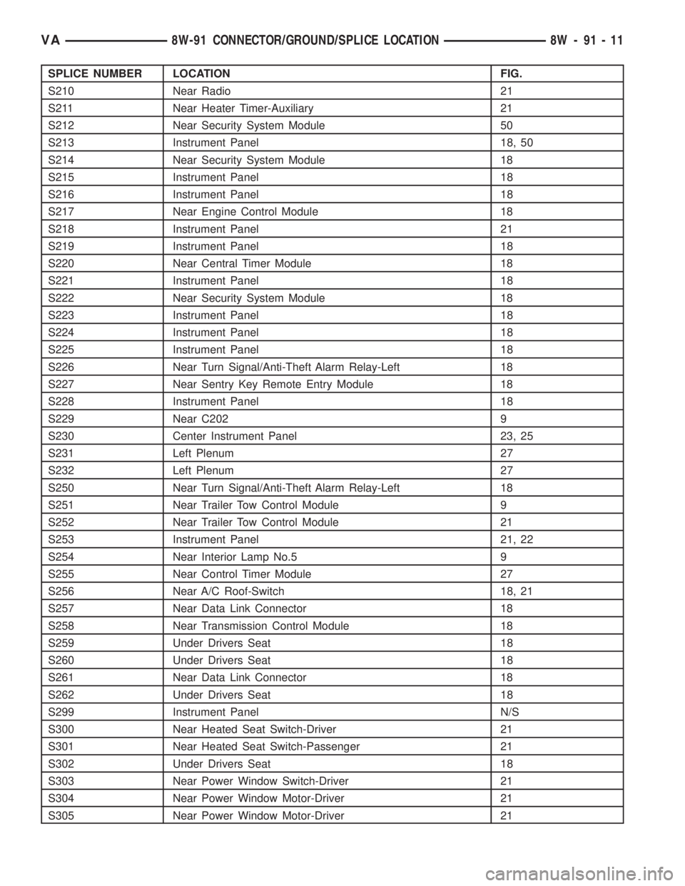
SPLICE NUMBER LOCATION FIG.
S210 Near Radio 21
S211 Near Heater Timer-Auxiliary 21
S212 Near Security System Module 50
S213 Instrument Panel 18, 50
S214 Near Security System Module 18
S215 Instrument Panel 18
S216 Instrument Panel 18
S217 Near Engine Control Module 18
S218 Instrument Panel 21
S219 Instrument Panel 18
S220 Near Central Timer Module 18
S221 Instrument Panel 18
S222 Near Security System Module 18
S223 Instrument Panel 18
S224 Instrument Panel 18
S225 Instrument Panel 18
S226 Near Turn Signal/Anti-Theft Alarm Relay-Left 18
S227 Near Sentry Key Remote Entry Module 18
S228 Instrument Panel 18
S229 Near C202 9
S230 Center Instrument Panel 23, 25
S231 Left Plenum 27
S232 Left Plenum 27
S250 Near Turn Signal/Anti-Theft Alarm Relay-Left 18
S251 Near Trailer Tow Control Module 9
S252 Near Trailer Tow Control Module 21
S253 Instrument Panel 21, 22
S254 Near Interior Lamp No.5 9
S255 Near Control Timer Module 27
S256 Near A/C Roof-Switch 18, 21
S257 Near Data Link Connector 18
S258 Near Transmission Control Module 18
S259 Under Drivers Seat 18
S260 Under Drivers Seat 18
S261 Near Data Link Connector 18
S262 Under Drivers Seat 18
S299 Instrument Panel N/S
S300 Near Heated Seat Switch-Driver 21
S301 Near Heated Seat Switch-Passenger 21
S302 Under Drivers Seat 18
S303 Near Power Window Switch-Driver 21
S304 Near Power Window Motor-Driver 21
S305 Near Power Window Motor-Driver 21
VA8W-91 CONNECTOR/GROUND/SPLICE LOCATION 8W - 91 - 11
Page 1561 of 2305
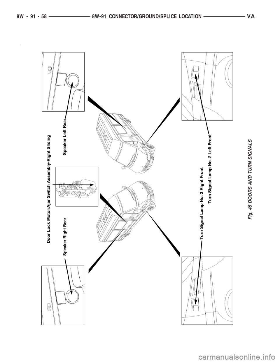
Fig. 45 DOORS AND TURN SIGNALS
8W - 91 - 58 8W-91 CONNECTOR/GROUND/SPLICE LOCATIONVA
Page 1639 of 2305
(14) Remove riveting tool.
(15) Turn over tool moving assembly insert to the
riveting profile.
NOTE: Rivet pins of the riveted link individually.
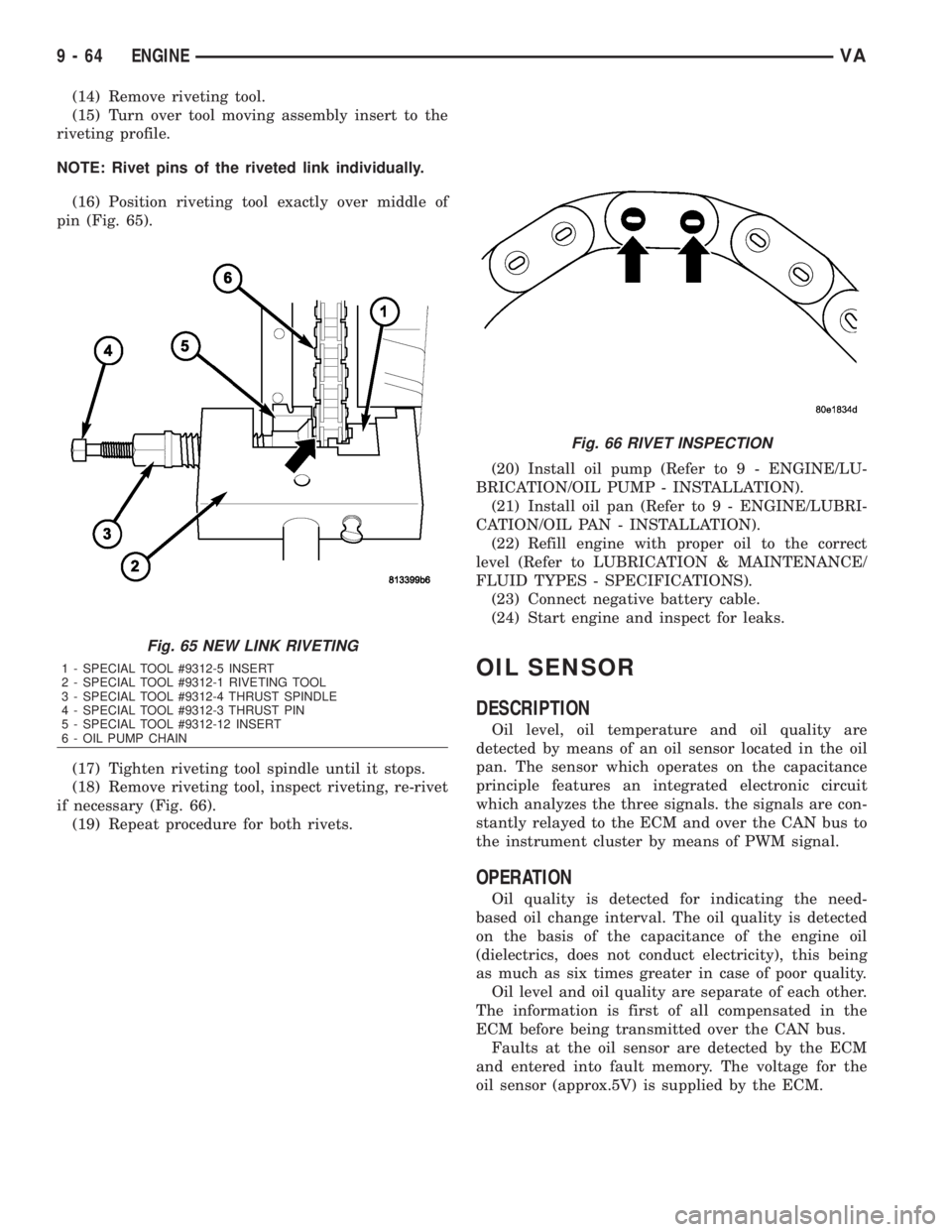
(16) Position riveting tool exactly over middle of
pin (Fig. 65).
(17) Tighten riveting tool spindle until it stops.
(18) Remove riveting tool, inspect riveting, re-rivet
if necessary (Fig. 66).
(19) Repeat procedure for both rivets.(20) Install oil pump (Refer to 9 - ENGINE/LU-
BRICATION/OIL PUMP - INSTALLATION).
(21) Install oil pan (Refer to 9 - ENGINE/LUBRI-
CATION/OIL PAN - INSTALLATION).
(22) Refill engine with proper oil to the correct
level (Refer to LUBRICATION & MAINTENANCE/
FLUID TYPES - SPECIFICATIONS).
(23) Connect negative battery cable.
(24) Start engine and inspect for leaks.
OIL SENSOR
DESCRIPTION
Oil level, oil temperature and oil quality are
detected by means of an oil sensor located in the oil
pan. The sensor which operates on the capacitance
principle features an integrated electronic circuit
which analyzes the three signals. the signals are con-
stantly relayed to the ECM and over the CAN bus to
the instrument cluster by means of PWM signal.
OPERATION
Oil quality is detected for indicating the need-
based oil change interval. The oil quality is detected
on the basis of the capacitance of the engine oil
(dielectrics, does not conduct electricity), this being
as much as six times greater in case of poor quality.
Oil level and oil quality are separate of each other.
The information is first of all compensated in the
ECM before being transmitted over the CAN bus.
Faults at the oil sensor are detected by the ECM
and entered into fault memory. The voltage for the
oil sensor (approx.5V) is supplied by the ECM.
Fig. 65 NEW LINK RIVETING
1 - SPECIAL TOOL #9312-5 INSERT
2 - SPECIAL TOOL #9312-1 RIVETING TOOL
3 - SPECIAL TOOL #9312-4 THRUST SPINDLE
4 - SPECIAL TOOL #9312-3 THRUST PIN
5 - SPECIAL TOOL #9312-12 INSERT
6 - OIL PUMP CHAIN
Fig. 66 RIVET INSPECTION
9 - 64 ENGINEVA
Page 1693 of 2305
INSTALLATION - HIGH PRESSURE LINES
WARNING: NO SPARKS, OPEN FLAMES OR SMOK-
ING. RISK OF POISONING FROM INHALING AND
SWALLOWING FUEL. RISK OF INJURY TO EYES
AND SKIN FROM CONTACT WITH FUEL. POUR
FUELS ONLY INTO SUITABLE AND APPROPRI-
ATELY MARKED CONTAINERS. WEAR PROTECTIVE
CLOTHING.
(1) Loosen the fuel rail mounting bolts to install
lines free of stress.
CAUTION: Inspect sealing cone at lines. Replace if
compression points exist. Ensure lines are exactly
located.
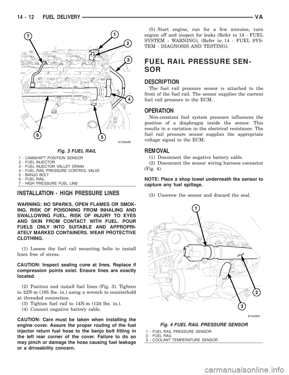
(2) Position and install fuel lines (Fig. 3). Tighten
to 22N´m (195 lbs. in.) using a wrench to counterhold
at threaded connection.
(3) Tighten fuel rail to 14N´m (124 lbs. in.).
(4) Connect negative battery cable.
CAUTION: Care must be taken when installing the
engine cover. Assure the proper routing of the fuel
injector return fuel hose to the banjo bolt fitting in
the left rear corner of the cover. Failure to do so
may pinch or damage the hose causing fuel leakage
or a driveability concern.(5) Start engine, run for a few minutes, turn
engine off and inspect for leaks (Refer to 14 - FUEL
SYSTEM - WARNING), (Refer to 14 - FUEL SYS-
TEM - DIAGNOSIS AND TESTING).
FUEL RAIL PRESSURE SEN-
SOR
DESCRIPTION
The fuel rail pressure sensor is attached to the
front of the fuel rail. The sensor supplies the current
fuel rail pressure to the ECM.
OPERATION
Non-constant fuel system pressure influences the
position of a diaphragm inside the sensor. This
results in a variation in the electrical resistance. The
fuel rail pressure sensor supplies the appropriate
voltage signal to the ECM.
REMOVAL
(1) Disconnect the negative battery cable.
(2) Disconnect the sensor wiring harness connector
(Fig. 4).
NOTE: Place a shop towel underneath the sensor to
capture any fuel spillage.
(3) Unscrew the sensor and discard the seal.
Fig. 3 FUEL RAIL
1 - CAMSHAFT POSITION SENSOR
2 - FUEL INJECTOR
3 - FUEL INJECTOR VALLEY DRAIN
4 - FUEL RAIL PRESSURE CONTROL VALVE
5 - BANJO BOLT
6 - FUEL RAIL
7 - HIGH PRESSURE FUEL LINE
Fig. 4 FUEL RAIL PRESSURE SENSOR
1 - FUEL RAIL PRESSURE SENSOR
2 - FUEL RAIL
3 - COOLANT TEMPERATURE SENSOR
14 - 12 FUEL DELIVERYVA
Page 1702 of 2305
FUEL QUANTITY CONTROL
VA LV E
DESCRIPTION
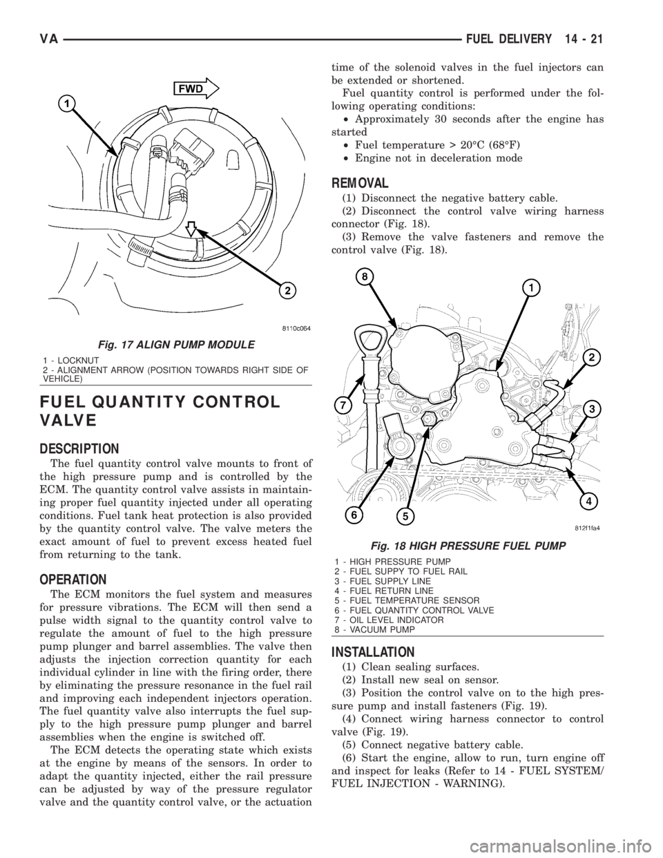
The fuel quantity control valve mounts to front of
the high pressure pump and is controlled by the
ECM. The quantity control valve assists in maintain-
ing proper fuel quantity injected under all operating
conditions. Fuel tank heat protection is also provided
by the quantity control valve. The valve meters the
exact amount of fuel to prevent excess heated fuel
from returning to the tank.
OPERATION
The ECM monitors the fuel system and measures
for pressure vibrations. The ECM will then send a
pulse width signal to the quantity control valve to
regulate the amount of fuel to the high pressure
pump plunger and barrel assemblies. The valve then
adjusts the injection correction quantity for each
individual cylinder in line with the firing order, there
by eliminating the pressure resonance in the fuel rail
and improving each independent injectors operation.
The fuel quantity valve also interrupts the fuel sup-
ply to the high pressure pump plunger and barrel
assemblies when the engine is switched off.
The ECM detects the operating state which exists
at the engine by means of the sensors. In order to
adapt the quantity injected, either the rail pressure
can be adjusted by way of the pressure regulator
valve and the quantity control valve, or the actuationtime of the solenoid valves in the fuel injectors can
be extended or shortened.
Fuel quantity control is performed under the fol-
lowing operating conditions:
²Approximately 30 seconds after the engine has
started
²Fuel temperature > 20ÉC (68ÉF)
²Engine not in deceleration mode
REMOVAL
(1) Disconnect the negative battery cable.
(2) Disconnect the control valve wiring harness
connector (Fig. 18).
(3) Remove the valve fasteners and remove the
control valve (Fig. 18).
INSTALLATION
(1) Clean sealing surfaces.
(2) Install new seal on sensor.
(3) Position the control valve on to the high pres-
sure pump and install fasteners (Fig. 19).
(4) Connect wiring harness connector to control
valve (Fig. 19).
(5) Connect negative battery cable.
(6) Start the engine, allow to run, turn engine off
and inspect for leaks (Refer to 14 - FUEL SYSTEM/
FUEL INJECTION - WARNING).
Fig. 17 ALIGN PUMP MODULE
1 - LOCKNUT
2 - ALIGNMENT ARROW (POSITION TOWARDS RIGHT SIDE OF
VEHICLE)
Fig. 18 HIGH PRESSURE FUEL PUMP
1 - HIGH PRESSURE PUMP
2 - FUEL SUPPY TO FUEL RAIL
3 - FUEL SUPPLY LINE
4 - FUEL RETURN LINE
5 - FUEL TEMPERATURE SENSOR
6 - FUEL QUANTITY CONTROL VALVE
7 - OIL LEVEL INDICATOR
8 - VACUUM PUMP
VAFUEL DELIVERY 14 - 21
Page 1716 of 2305
(3) Install engine cover.
(4) Reconnect negative battery cable.
CRANKSHAFT POSITION SEN-
SOR
DESCRIPTION
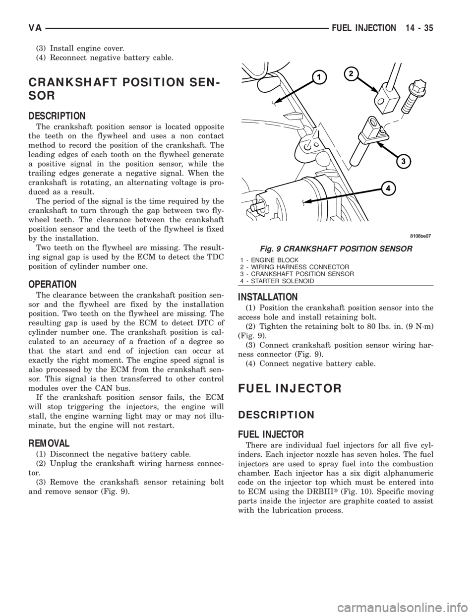
The crankshaft position sensor is located opposite
the teeth on the flywheel and uses a non contact
method to record the position of the crankshaft. The
leading edges of each tooth on the flywheel generate
a positive signal in the position sensor, while the
trailing edges generate a negative signal. When the
crankshaft is rotating, an alternating voltage is pro-
duced as a result.
The period of the signal is the time required by the
crankshaft to turn through the gap between two fly-
wheel teeth. The clearance between the crankshaft
position sensor and the teeth of the flywheel is fixed
by the installation.
Two teeth on the flywheel are missing. The result-
ing signal gap is used by the ECM to detect the TDC
position of cylinder number one.
OPERATION
The clearance between the crankshaft position sen-
sor and the flywheel are fixed by the installation
position. Two teeth on the flywheel are missing. The
resulting gap is used by the ECM to detect DTC of
cylinder number one. The crankshaft position is cal-
culated to an accuracy of a fraction of a degree so
that the start and end of injection can occur at
exactly the right moment. The engine speed signal is
also processed by the ECM from the crankshaft sen-
sor. This signal is then transferred to other control
modules over the CAN bus.
If the crankshaft position sensor fails, the ECM
will stop triggering the injectors, the engine will
stall, the engine warning light may or may not illu-
minate, but the engine will not restart.
REMOVAL
(1) Disconnect the negative battery cable.
(2) Unplug the crankshaft wiring harness connec-
tor.
(3) Remove the crankshaft sensor retaining bolt
and remove sensor (Fig. 9).
INSTALLATION
(1) Position the crankshaft position sensor into the
access hole and install retaining bolt.
(2) Tighten the retaining bolt to 80 lbs. in. (9 N´m)
(Fig. 9).
(3) Connect crankshaft position sensor wiring har-
ness connector (Fig. 9).
(4) Connect negative battery cable.
FUEL INJECTOR
DESCRIPTION
FUEL INJECTOR
There are individual fuel injectors for all five cyl-
inders. Each injector nozzle has seven holes. The fuel
injectors are used to spray fuel into the combustion
chamber. Each injector has a six digit alphanumeric
code on the injector top which must be entered into
to ECM using the DRBIIIt(Fig. 10). Specific moving
parts inside the injector are graphite coated to assist
with the lubrication process.
Fig. 9 CRANKSHAFT POSITION SENSOR
1 - ENGINE BLOCK
2 - WIRING HARNESS CONNECTOR
3 - CRANKSHAFT POSITION SENSOR
4 - STARTER SOLENOID
VAFUEL INJECTION 14 - 35
Page 1720 of 2305
INSTALLATION
WARNING: NO SPARKS, OPEN FLAMES OR SMOK-
ING. RISK OF POISONING FROM INHALING AND
SWALLOWING FUEL. RISK OF INJURY TO EYES
AND SKIN FROM CONTACT WITH FUEL. POUR
FUELS ONLY INTO SUITABLE AND APPROPRI-
ATELY MARKED CONTAINERS. WEAR PROTECTIVE
CLOTHING.
NOTE: When removing injectors, the seal rings and
retaining stretch bolts must always be replaced.
Coat the injector body with the anti-seize com-
pound before installing. Keep lubricant away from
the injector nozzle.
(1) Clean injectors and recesses (Refer to 14 -
FUEL SYSTEM/FUEL INJECTION/FUEL INJEC-
TOR - STANDARD PROCEDURE).
(2) Coat injector body with anti seize lubricant
then install injectors with new seals.
(3) Install tensioning claws with new screws at
injectors. Tighten screws in two stages, 7 N´m (62
lbs. in.) then 90É (Fig. 13).
NOTE: If locking clamp has been pulled off at injec-
tor, the locking clamp must be replaced.
(4) Position fuel return line at injectors and secure
locking clamps (Fig. 13).
NOTE: Counterhold injection lines with wrench
socket at threaded connections of injectors. DO
NOT over tighten.
(5) Install high pressure injection lines (Refer to
14 - FUEL SYSTEM/FUEL DELIVERY/FUEL LINES
- INSTALLATION).
(6) Reconnect injector electrical connectors (Fig.
13).
(7) Connect negative battery cable.
NOTE: Fuel Injectors have different flow rates.
When injectors are removed, re-enter all injector six
digit codes.
(8) Program all injector codes into the ECM using
the scan tool.
(9) Start engine, allow to run, turn engine off and
inspect for leaks (Refer to 14 - FUEL SYSTEM -
WARNING).
CAUTION: Care must be taken when installing the
engine cover. Assure the proper routing of the fuel
injector return fuel hose to the banjo bolt fitting in
the left rear corner of the cover. Failure to do so
may pinch or damage the hose causing fuel leakage
or a driveability concern.(10) Install engine cover (Refer to 9 - ENGINE -
INSTALLATION)..
FUEL PRESSURE SENSOR
DESCRIPTION
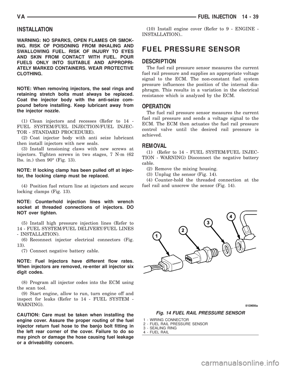
The fuel rail pressure sensor measures the current
fuel rail pressure and supplies an appropriate voltage
signal to the ECM. The non-constant fuel system
pressure influences the position of the internal dia-
phragm. This results in a variation in the electrical
resistance which is analyzed by the ECM.
OPERATION
The fuel rail pressure sensor measures the current
fuel rail pressure and sends a voltage signal to the
ECM. The ECM then actuates the fuel rail pressure
control valve until the desired rail pressure is
achieved.
REMOVAL
(1) (Refer to 14 - FUEL SYSTEM/FUEL INJEC-
TION - WARNING) Disconnect the negative battery
cable.
(2) Remove the mixing housing.
(3) Unplug the sensor (Fig. 14).
(4) Counter-hold the threaded connection at the
fuel rail and unscrew the sensor (Fig. 14).
Fig. 14 FUEL RAIL PRESSURE SENSOR
1 - WIRING CONNECTOR
2 - FUEL RAIL PRESSURE SENSOR
3 - SEALING RING
4 - FUEL RAIL
VAFUEL INJECTION 14 - 39
Page 1721 of 2305
INSTALLATION
(1) (Refer to 14 - FUEL SYSTEM/FUEL INJEC-
TION - WARNING) Install the sealing ring on to the
sensor (Fig. 14).
(2) Screw the sensor in to the fuel rail. Counter-
hold the threaded connection and tighten the sensor
to 18 lbs. ft. (25 N´m.) (Fig. 14).
(3) Connect the wiring harness to the sensor.
(4) Install the mixing housing.
CAUTION: Care must be taken when installing the
engine cover. Assure the proper routing of the fuel
injector return fuel hose to the banjo bolt fitting in
the left rear corner of the cover. Failure to do so
may pinch or damage the hose causing fuel leakage
or a driveability concern.
(5) Connect negative battery cable.
FUEL PRESSURE SOLENOID
DESCRIPTION
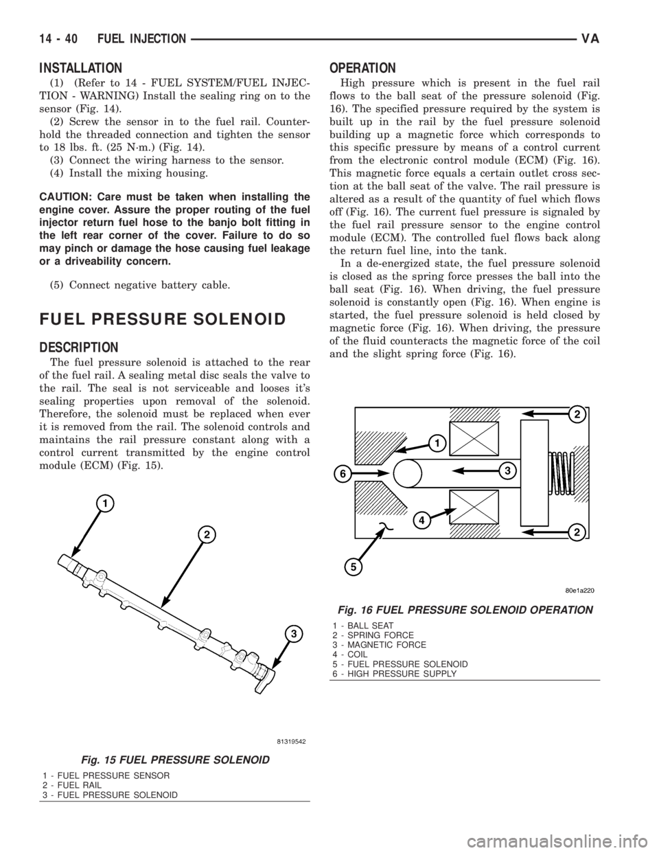
The fuel pressure solenoid is attached to the rear
of the fuel rail. A sealing metal disc seals the valve to
the rail. The seal is not serviceable and looses it's
sealing properties upon removal of the solenoid.
Therefore, the solenoid must be replaced when ever
it is removed from the rail. The solenoid controls and
maintains the rail pressure constant along with a
control current transmitted by the engine control
module (ECM) (Fig. 15).
OPERATION
High pressure which is present in the fuel rail
flows to the ball seat of the pressure solenoid (Fig.
16). The specified pressure required by the system is
built up in the rail by the fuel pressure solenoid
building up a magnetic force which corresponds to
this specific pressure by means of a control current
from the electronic control module (ECM) (Fig. 16).
This magnetic force equals a certain outlet cross sec-
tion at the ball seat of the valve. The rail pressure is
altered as a result of the quantity of fuel which flows
off (Fig. 16). The current fuel pressure is signaled by
the fuel rail pressure sensor to the engine control
module (ECM). The controlled fuel flows back along
the return fuel line, into the tank.
In a de-energized state, the fuel pressure solenoid
is closed as the spring force presses the ball into the
ball seat (Fig. 16). When driving, the fuel pressure
solenoid is constantly open (Fig. 16). When engine is
started, the fuel pressure solenoid is held closed by
magnetic force (Fig. 16). When driving, the pressure
of the fluid counteracts the magnetic force of the coil
and the slight spring force (Fig. 16).
Fig. 15 FUEL PRESSURE SOLENOID
1 - FUEL PRESSURE SENSOR
2 - FUEL RAIL
3 - FUEL PRESSURE SOLENOID
Fig. 16 FUEL PRESSURE SOLENOID OPERATION
1 - BALL SEAT
2 - SPRING FORCE
3 - MAGNETIC FORCE
4 - COIL
5 - FUEL PRESSURE SOLENOID
6 - HIGH PRESSURE SUPPLY
14 - 40 FUEL INJECTIONVA