2006 MERCEDES-BENZ SPRINTER turn signal
[x] Cancel search: turn signalPage 2051 of 2305
(5) Install the two A/C-heater control retaining
screws. Tighten the screws to 2 N´m (17 in. lbs.).
(6) Install the center bezel onto the instrument
panel (Refer to 23 - BODY/INSTRUMENT PANEL/
INSTRUMENT PANEL CENTER BEZEL - INSTAL-
LATION).
(7) Reconnect the negative battery cable.
A / C PRESSURE TRANS-
DUCER
DESCRIPTION
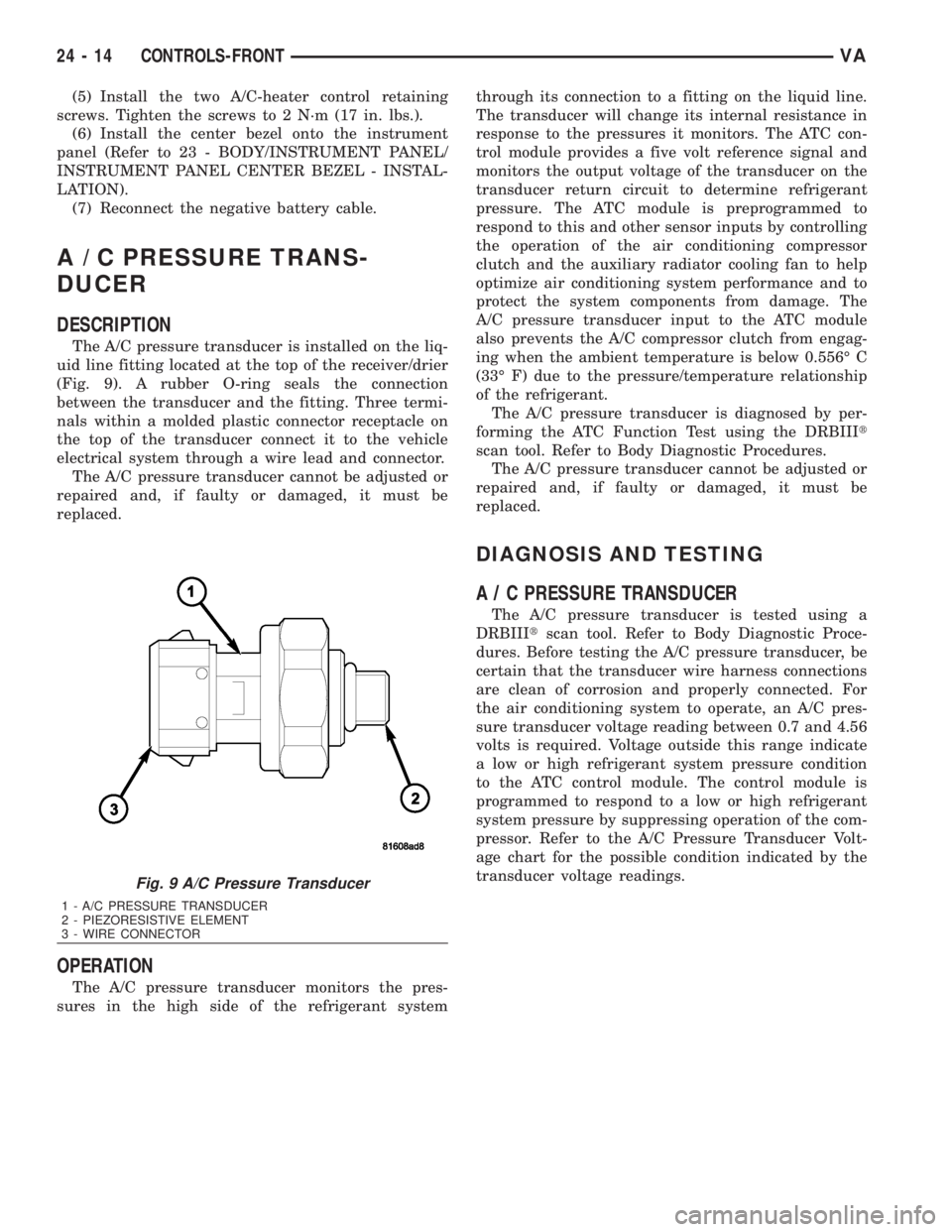
The A/C pressure transducer is installed on the liq-
uid line fitting located at the top of the receiver/drier
(Fig. 9). A rubber O-ring seals the connection
between the transducer and the fitting. Three termi-
nals within a molded plastic connector receptacle on
the top of the transducer connect it to the vehicle
electrical system through a wire lead and connector.
The A/C pressure transducer cannot be adjusted or
repaired and, if faulty or damaged, it must be
replaced.
OPERATION
The A/C pressure transducer monitors the pres-
sures in the high side of the refrigerant systemthrough its connection to a fitting on the liquid line.
The transducer will change its internal resistance in
response to the pressures it monitors. The ATC con-
trol module provides a five volt reference signal and
monitors the output voltage of the transducer on the
transducer return circuit to determine refrigerant
pressure. The ATC module is preprogrammed to
respond to this and other sensor inputs by controlling
the operation of the air conditioning compressor
clutch and the auxiliary radiator cooling fan to help
optimize air conditioning system performance and to
protect the system components from damage. The
A/C pressure transducer input to the ATC module
also prevents the A/C compressor clutch from engag-
ing when the ambient temperature is below 0.556É C
(33É F) due to the pressure/temperature relationship
of the refrigerant.
The A/C pressure transducer is diagnosed by per-
forming the ATC Function Test using the DRBIIIt
scan tool. Refer to Body Diagnostic Procedures.
The A/C pressure transducer cannot be adjusted or
repaired and, if faulty or damaged, it must be
replaced.
DIAGNOSIS AND TESTING
A / C PRESSURE TRANSDUCER
The A/C pressure transducer is tested using a
DRBIIItscan tool. Refer to Body Diagnostic Proce-
dures. Before testing the A/C pressure transducer, be
certain that the transducer wire harness connections
are clean of corrosion and properly connected. For
the air conditioning system to operate, an A/C pres-
sure transducer voltage reading between 0.7 and 4.56
volts is required. Voltage outside this range indicate
a low or high refrigerant system pressure condition
to the ATC control module. The control module is
programmed to respond to a low or high refrigerant
system pressure by suppressing operation of the com-
pressor. Refer to the A/C Pressure Transducer Volt-
age chart for the possible condition indicated by the
transducer voltage readings.
Fig. 9 A/C Pressure Transducer
1 - A/C PRESSURE TRANSDUCER
2 - PIEZORESISTIVE ELEMENT
3 - WIRE CONNECTOR
24 - 14 CONTROLS-FRONTVA
Page 2056 of 2305
BLOWER MOTOR SWITCH
DESCRIPTION
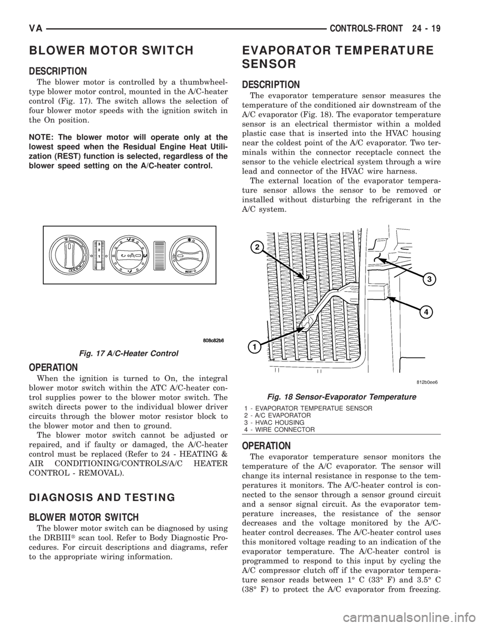
The blower motor is controlled by a thumbwheel-
type blower motor control, mounted in the A/C-heater
control (Fig. 17). The switch allows the selection of
four blower motor speeds with the ignition switch in
the On position.
NOTE: The blower motor will operate only at the
lowest speed when the Residual Engine Heat Utili-
zation (REST) function is selected, regardless of the
blower speed setting on the A/C-heater control.
OPERATION
When the ignition is turned to On, the integral
blower motor switch within the ATC A/C-heater con-
trol supplies power to the blower motor switch. The
switch directs power to the individual blower driver
circuits through the blower motor resistor block to
the blower motor and then to ground.
The blower motor switch cannot be adjusted or
repaired, and if faulty or damaged, the A/C-heater
control must be replaced (Refer to 24 - HEATING &
AIR CONDITIONING/CONTROLS/A/C HEATER
CONTROL - REMOVAL).
DIAGNOSIS AND TESTING
BLOWER MOTOR SWITCH
The blower motor switch can be diagnosed by using
the DRBIIItscan tool. Refer to Body Diagnostic Pro-
cedures. For circuit descriptions and diagrams, refer
to the appropriate wiring information.
EVAPORATOR TEMPERATURE
SENSOR
DESCRIPTION
The evaporator temperature sensor measures the
temperature of the conditioned air downstream of the
A/C evaporator (Fig. 18). The evaporator temperature
sensor is an electrical thermistor within a molded
plastic case that is inserted into the HVAC housing
near the coldest point of the A/C evaporator. Two ter-
minals within the connector receptacle connect the
sensor to the vehicle electrical system through a wire
lead and connector of the HVAC wire harness.
The external location of the evaporator tempera-
ture sensor allows the sensor to be removed or
installed without disturbing the refrigerant in the
A/C system.
OPERATION
The evaporator temperature sensor monitors the
temperature of the A/C evaporator. The sensor will
change its internal resistance in response to the tem-
peratures it monitors. The A/C-heater control is con-
nected to the sensor through a sensor ground circuit
and a sensor signal circuit. As the evaporator tem-
perature increases, the resistance of the sensor
decreases and the voltage monitored by the A/C-
heater control decreases. The A/C-heater control uses
this monitored voltage reading to an indication of the
evaporator temperature. The A/C-heater control is
programmed to respond to this input by cycling the
A/C compressor clutch off if the evaporator tempera-
ture sensor reads between 1É C (33É F) and 3.5É C
(38É F) to protect the A/C evaporator from freezing.
Fig. 17 A/C-Heater Control
Fig. 18 Sensor-Evaporator Temperature
1 - EVAPORATOR TEMPERATUE SENSOR
2 - A/C EVAPORATOR
3 - HVAC HOUSING
4 - WIRE CONNECTOR
VACONTROLS-FRONT 24 - 19
Page 2059 of 2305
NOTE: While holding the A/C-heater control in the
installation position, verify that the control cables
are not twisted.
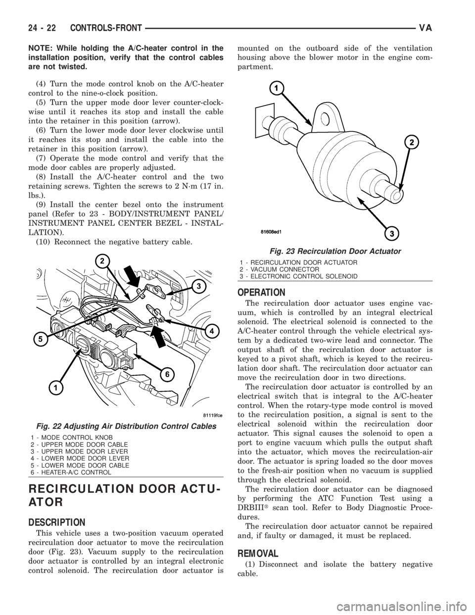
(4) Turn the mode control knob on the A/C-heater
control to the nine-o-clock position.
(5) Turn the upper mode door lever counter-clock-
wise until it reaches its stop and install the cable
into the retainer in this position (arrow).
(6) Turn the lower mode door lever clockwise until
it reaches its stop and install the cable into the
retainer in this position (arrow).
(7) Operate the mode control and verify that the
mode door cables are properly adjusted.
(8) Install the A/C-heater control and the two
retaining screws. Tighten the screws to 2 N´m (17 in.
lbs.).
(9) Install the center bezel onto the instrument
panel (Refer to 23 - BODY/INSTRUMENT PANEL/
INSTRUMENT PANEL CENTER BEZEL - INSTAL-
LATION).
(10) Reconnect the negative battery cable.
RECIRCULATION DOOR ACTU-
ATOR
DESCRIPTION
This vehicle uses a two-position vacuum operated
recirculation door actuator to move the recirculation
door (Fig. 23). Vacuum supply to the recirculation
door actuator is controlled by an integral electronic
control solenoid. The recirculation door actuator ismounted on the outboard side of the ventilation
housing above the blower motor in the engine com-
partment.
OPERATION
The recirculation door actuator uses engine vac-
uum, which is controlled by an integral electrical
solenoid. The electrical solenoid is connected to the
A/C-heater control through the vehicle electrical sys-
tem by a dedicated two-wire lead and connector. The
output shaft of the recirculation door actuator is
keyed to a pivot shaft, which is keyed to the recircu-
lation door shaft. The recirculation door actuator can
move the recirculation door in two directions.
The recirculation door actuator is controlled by an
electrical switch that is integral to the A/C-heater
control. When the rotary-type mode control is moved
to the recirculation position, a signal is sent to the
electrical solenoid within the recirculation door
actuator. This signal causes the solenoid to open a
port to engine vacuum which pulls the output shaft
into the actuator, which moves the recirculation-air
door. The actuator is spring loaded so the door moves
to the fresh-air position when no vacuum is supplied
through the electrical solenoid.
The recirculation door actuator can be diagnosed
by performing the ATC Function Test using a
DRBIIItscan tool. Refer to Body Diagnostic Proce-
dures.
The recirculation door actuator cannot be repaired
and, if faulty or damaged, it must be replaced.
REMOVAL
(1) Disconnect and isolate the battery negative
cable.
Fig. 22 Adjusting Air Distribution Control Cables
1 - MODE CONTROL KNOB
2 - UPPER MODE DOOR CABLE
3 - UPPER MODE DOOR LEVER
4 - LOWER MODE DOOR LEVER
5 - LOWER MODE DOOR CABLE
6 - HEATER-A/C CONTROL
Fig. 23 Recirculation Door Actuator
1 - RECIRCULATION DOOR ACTUATOR
2 - VACUUM CONNECTOR
3 - ELECTRONIC CONTROL SOLENOID
24 - 22 CONTROLS-FRONTVA
Page 2065 of 2305
INSTALLATION
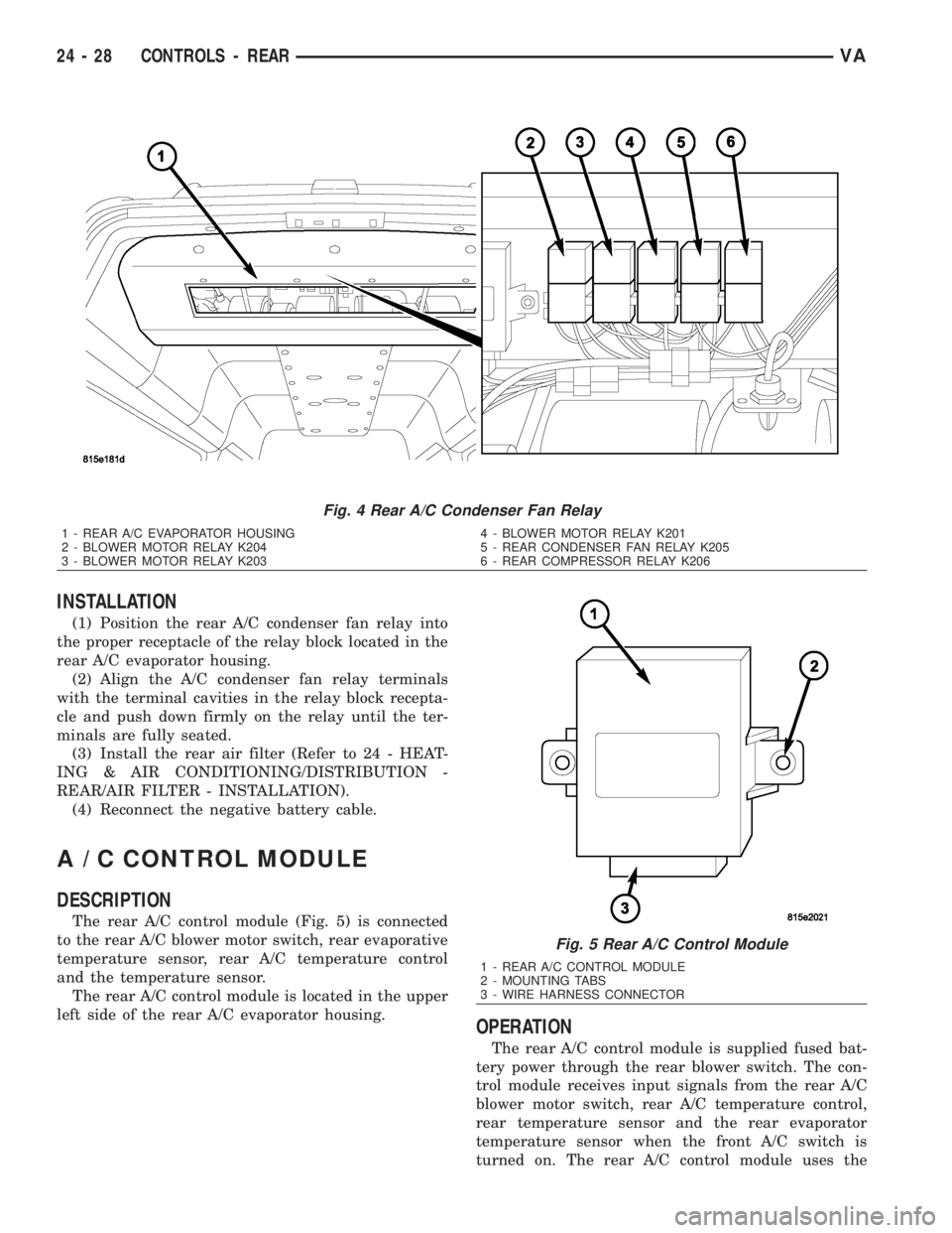
(1) Position the rear A/C condenser fan relay into
the proper receptacle of the relay block located in the
rear A/C evaporator housing.
(2) Align the A/C condenser fan relay terminals
with the terminal cavities in the relay block recepta-
cle and push down firmly on the relay until the ter-
minals are fully seated.
(3) Install the rear air filter (Refer to 24 - HEAT-
ING & AIR CONDITIONING/DISTRIBUTION -
REAR/AIR FILTER - INSTALLATION).
(4) Reconnect the negative battery cable.
A / C CONTROL MODULE
DESCRIPTION
The rear A/C control module (Fig. 5) is connected
to the rear A/C blower motor switch, rear evaporative
temperature sensor, rear A/C temperature control
and the temperature sensor.
The rear A/C control module is located in the upper
left side of the rear A/C evaporator housing.
OPERATION
The rear A/C control module is supplied fused bat-
tery power through the rear blower switch. The con-
trol module receives input signals from the rear A/C
blower motor switch, rear A/C temperature control,
rear temperature sensor and the rear evaporator
temperature sensor when the front A/C switch is
turned on. The rear A/C control module uses the
Fig. 4 Rear A/C Condenser Fan Relay
1 - REAR A/C EVAPORATOR HOUSING
2 - BLOWER MOTOR RELAY K204
3 - BLOWER MOTOR RELAY K2034 - BLOWER MOTOR RELAY K201
5 - REAR CONDENSER FAN RELAY K205
6 - REAR COMPRESSOR RELAY K206
Fig. 5 Rear A/C Control Module
1 - REAR A/C CONTROL MODULE
2 - MOUNTING TABS
3 - WIRE HARNESS CONNECTOR
24 - 28 CONTROLS - REARVA
Page 2069 of 2305
A / C LOW PRESSURE SWITCH
DESCRIPTION
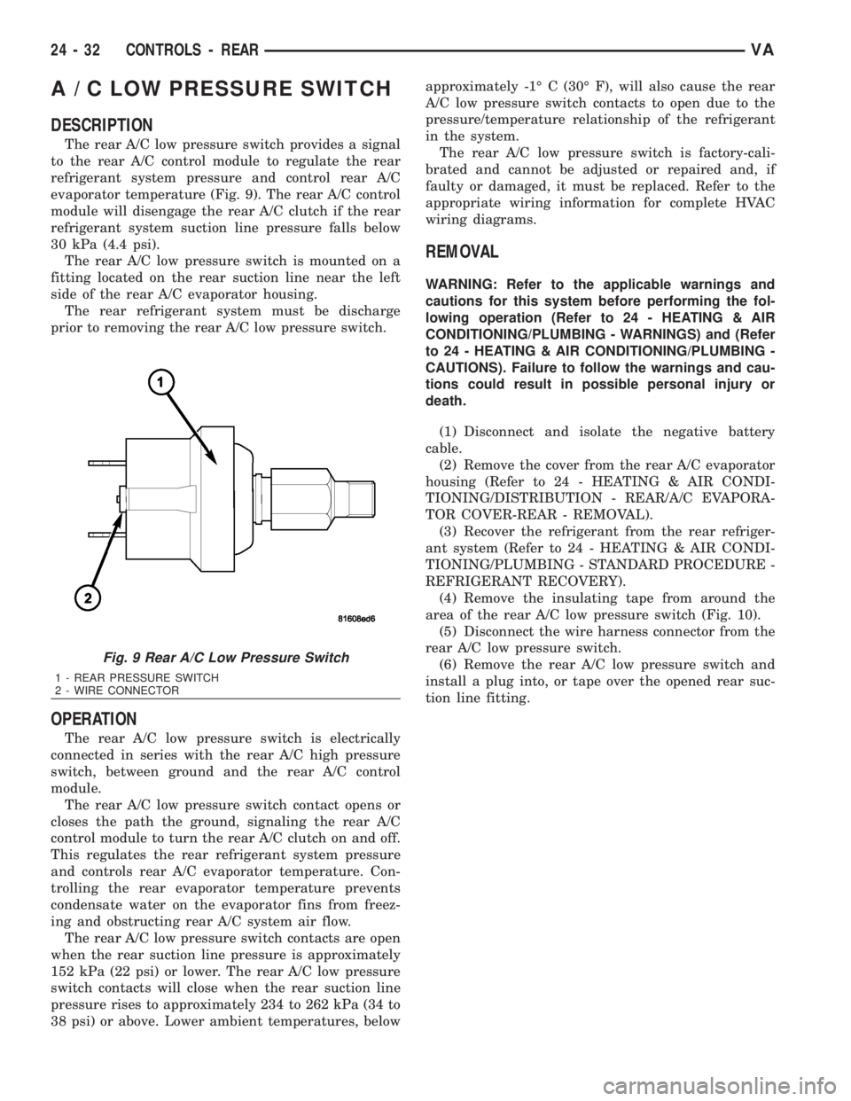
The rear A/C low pressure switch provides a signal
to the rear A/C control module to regulate the rear
refrigerant system pressure and control rear A/C
evaporator temperature (Fig. 9). The rear A/C control
module will disengage the rear A/C clutch if the rear
refrigerant system suction line pressure falls below
30 kPa (4.4 psi).
The rear A/C low pressure switch is mounted on a
fitting located on the rear suction line near the left
side of the rear A/C evaporator housing.
The rear refrigerant system must be discharge
prior to removing the rear A/C low pressure switch.
OPERATION
The rear A/C low pressure switch is electrically
connected in series with the rear A/C high pressure
switch, between ground and the rear A/C control
module.
The rear A/C low pressure switch contact opens or
closes the path the ground, signaling the rear A/C
control module to turn the rear A/C clutch on and off.
This regulates the rear refrigerant system pressure
and controls rear A/C evaporator temperature. Con-
trolling the rear evaporator temperature prevents
condensate water on the evaporator fins from freez-
ing and obstructing rear A/C system air flow.
The rear A/C low pressure switch contacts are open
when the rear suction line pressure is approximately
152 kPa (22 psi) or lower. The rear A/C low pressure
switch contacts will close when the rear suction line
pressure rises to approximately 234 to 262 kPa (34 to
38 psi) or above. Lower ambient temperatures, belowapproximately -1É C (30É F), will also cause the rear
A/C low pressure switch contacts to open due to the
pressure/temperature relationship of the refrigerant
in the system.
The rear A/C low pressure switch is factory-cali-
brated and cannot be adjusted or repaired and, if
faulty or damaged, it must be replaced. Refer to the
appropriate wiring information for complete HVAC
wiring diagrams.
REMOVAL
WARNING: Refer to the applicable warnings and
cautions for this system before performing the fol-
lowing operation (Refer to 24 - HEATING & AIR
CONDITIONING/PLUMBING - WARNINGS) and (Refer
to 24 - HEATING & AIR CONDITIONING/PLUMBING -
CAUTIONS). Failure to follow the warnings and cau-
tions could result in possible personal injury or
death.
(1) Disconnect and isolate the negative battery
cable.
(2) Remove the cover from the rear A/C evaporator
housing (Refer to 24 - HEATING & AIR CONDI-
TIONING/DISTRIBUTION - REAR/A/C EVAPORA-
TOR COVER-REAR - REMOVAL).
(3) Recover the refrigerant from the rear refriger-
ant system (Refer to 24 - HEATING & AIR CONDI-
TIONING/PLUMBING - STANDARD PROCEDURE -
REFRIGERANT RECOVERY).
(4) Remove the insulating tape from around the
area of the rear A/C low pressure switch (Fig. 10).
(5) Disconnect the wire harness connector from the
rear A/C low pressure switch.
(6) Remove the rear A/C low pressure switch and
install a plug into, or tape over the opened rear suc-
tion line fitting.
Fig. 9 Rear A/C Low Pressure Switch
1 - REAR PRESSURE SWITCH
2 - WIRE CONNECTOR
24 - 32 CONTROLS - REARVA
Page 2072 of 2305
INSTALLATION
(1) Position the rear blower motor relays into the
proper receptacle of the relay block located in the
rear A/C evaporator housing as necessary.
(2) Align the blower motor relay terminals with
the terminal cavities in the relay block receptacle
and push down firmly on the relay until the termi-
nals are fully seated.
(3) Install the rear air filter (Refer to 24 - HEAT-
ING & AIR CONDITIONING/DISTRIBUTION -
REAR/AIR FILTER - INSTALLATION).
(4) Reconnect the negative battery cable.
BLOWER MOTOR SWITCH
DESCRIPTION
The blower motor for the optional rear A/C system
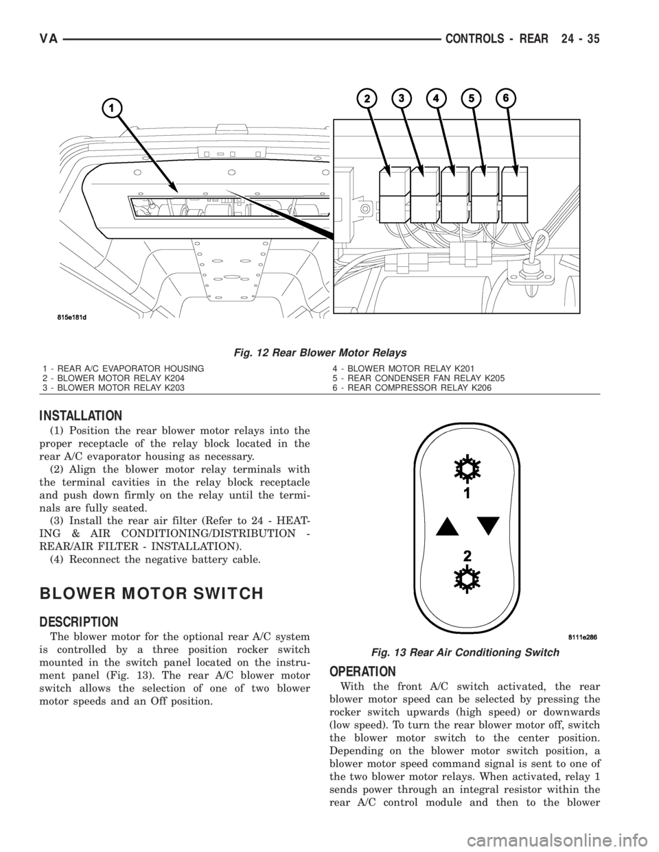
is controlled by a three position rocker switch
mounted in the switch panel located on the instru-
ment panel (Fig. 13). The rear A/C blower motor
switch allows the selection of one of two blower
motor speeds and an Off position.
OPERATION
With the front A/C switch activated, the rear
blower motor speed can be selected by pressing the
rocker switch upwards (high speed) or downwards
(low speed). To turn the rear blower motor off, switch
the blower motor switch to the center position.
Depending on the blower motor switch position, a
blower motor speed command signal is sent to one of
the two blower motor relays. When activated, relay 1
sends power through an integral resistor within the
rear A/C control module and then to the blower
Fig. 12 Rear Blower Motor Relays
1 - REAR A/C EVAPORATOR HOUSING
2 - BLOWER MOTOR RELAY K204
3 - BLOWER MOTOR RELAY K2034 - BLOWER MOTOR RELAY K201
5 - REAR CONDENSER FAN RELAY K205
6 - REAR COMPRESSOR RELAY K206
Fig. 13 Rear Air Conditioning Switch
VACONTROLS - REAR 24 - 35
Page 2077 of 2305
INSTALLATION
(1) Install the rear A/C temperature control into
the accessory switch panel. Make sure the retaining
tabs are fully engaged.
(2) Connect the wire harness connector to the rear
A/C temperature control.
(3) Install the accessory switch panel (Refer to 23 -
BODY/INSTRUMENT PANEL/ACCESSORY
SWITCH BEZEL - INSTALLATION).
(4) Reconnect the negative battery cable.
TEMPERATURE SENSOR
DESCRIPTION
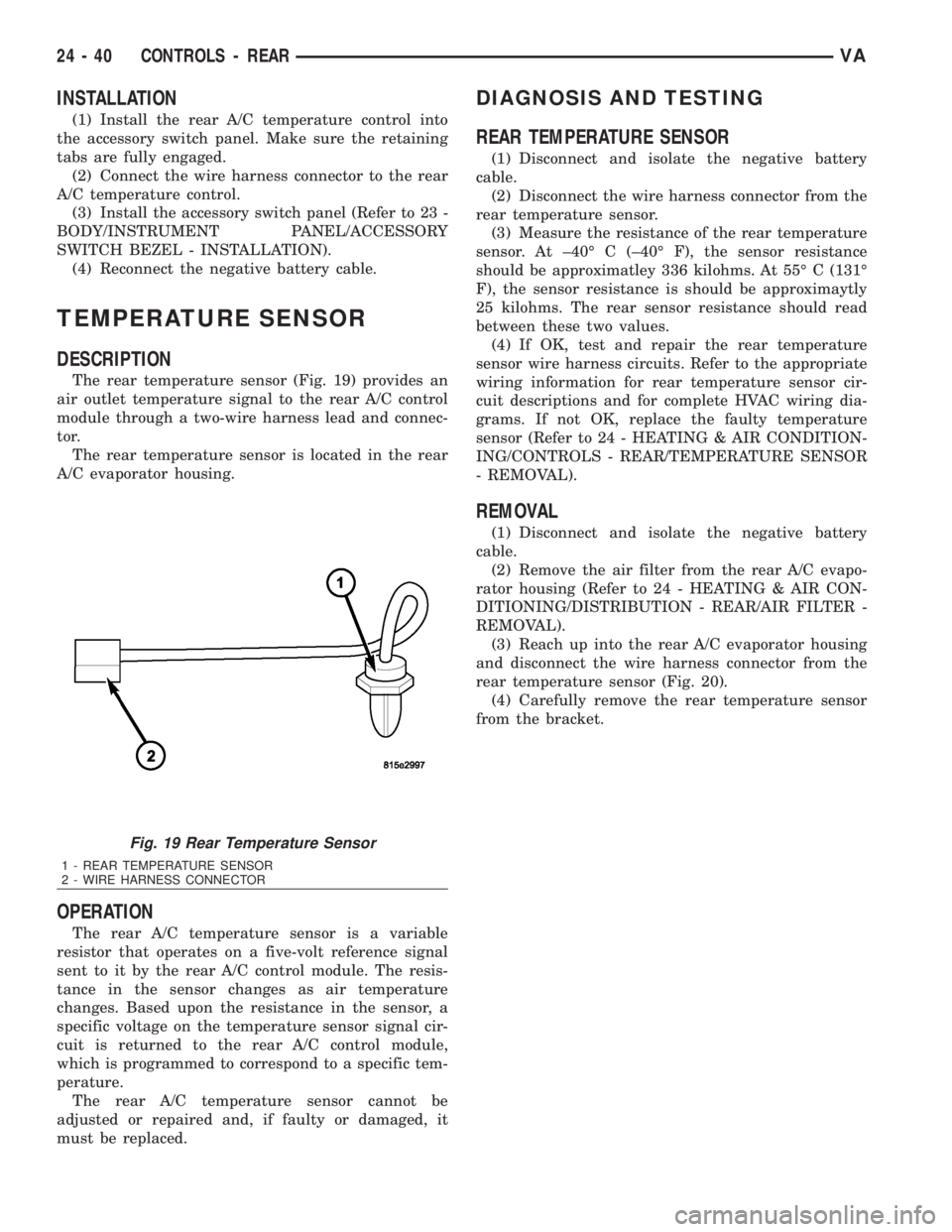
The rear temperature sensor (Fig. 19) provides an
air outlet temperature signal to the rear A/C control
module through a two-wire harness lead and connec-
tor.
The rear temperature sensor is located in the rear
A/C evaporator housing.
OPERATION
The rear A/C temperature sensor is a variable
resistor that operates on a five-volt reference signal
sent to it by the rear A/C control module. The resis-
tance in the sensor changes as air temperature
changes. Based upon the resistance in the sensor, a
specific voltage on the temperature sensor signal cir-
cuit is returned to the rear A/C control module,
which is programmed to correspond to a specific tem-
perature.
The rear A/C temperature sensor cannot be
adjusted or repaired and, if faulty or damaged, it
must be replaced.
DIAGNOSIS AND TESTING
REAR TEMPERATURE SENSOR
(1) Disconnect and isolate the negative battery
cable.
(2) Disconnect the wire harness connector from the
rear temperature sensor.
(3) Measure the resistance of the rear temperature
sensor. At ±40É C (±40É F), the sensor resistance
should be approximatley 336 kilohms. At 55É C (131É
F), the sensor resistance is should be approximaytly
25 kilohms. The rear sensor resistance should read
between these two values.
(4) If OK, test and repair the rear temperature
sensor wire harness circuits. Refer to the appropriate
wiring information for rear temperature sensor cir-
cuit descriptions and for complete HVAC wiring dia-
grams. If not OK, replace the faulty temperature
sensor (Refer to 24 - HEATING & AIR CONDITION-
ING/CONTROLS - REAR/TEMPERATURE SENSOR
- REMOVAL).
REMOVAL
(1) Disconnect and isolate the negative battery
cable.
(2) Remove the air filter from the rear A/C evapo-
rator housing (Refer to 24 - HEATING & AIR CON-
DITIONING/DISTRIBUTION - REAR/AIR FILTER -
REMOVAL).
(3) Reach up into the rear A/C evaporator housing
and disconnect the wire harness connector from the
rear temperature sensor (Fig. 20).
(4) Carefully remove the rear temperature sensor
from the bracket.
Fig. 19 Rear Temperature Sensor
1 - REAR TEMPERATURE SENSOR
2 - WIRE HARNESS CONNECTOR
24 - 40 CONTROLS - REARVA
Page 2155 of 2305
OPERATION
The mass of the air supplied to the cylinders per
stroke is the decisive factor for determining the opti-
mum quantity of exhaust gas for the operating con-
dition. This is calculated from the Mass Air Flow
sensor information.
The ECM evaluates this signal as well as that
from the Charge Air Pressure sensor, and outputs a
PWM signal in accordance with one of the maps
stored in it. The signal is sent to the exhaust gas
recirculation valve. The map is formulated to keep
the NOx as low as possible. The EGR valve is actu-
ated by an electric positioning motor and has a self
cleaning function. Every time the ignition switch is
turned off, the valve rotates twice to eliminate any
carbon deposits.
REMOVAL
NOTE: The EGR and EGR Cooler are serviced as an
assembly.
(1) Disconnect the negative battery cable.
(2) Partailly drain the cooling system (Refer to 7 -
COOLING/ENGINE/COOLANT - STANDARD PRO-
CEDURE).
(3) Lift up on the charge air hose retaining clip at
the intake manifold and disconnect hose with seal
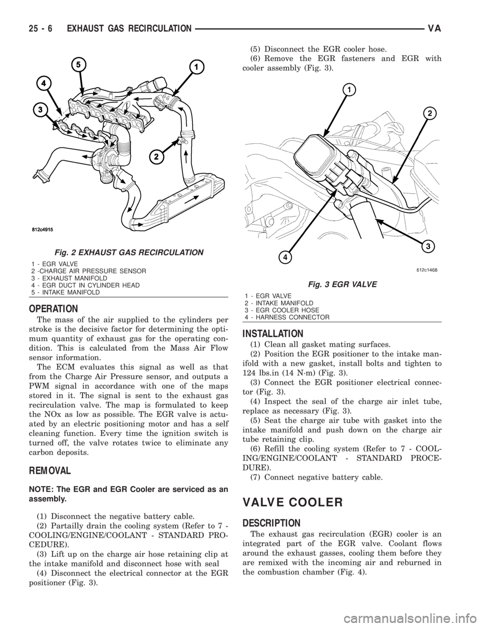
(4) Disconnect the electrical connector at the EGR
positioner (Fig. 3).(5) Disconnect the EGR cooler hose.
(6) Remove the EGR fasteners and EGR with
cooler assembly (Fig. 3).
INSTALLATION
(1) Clean all gasket mating surfaces.
(2) Position the EGR positioner to the intake man-
ifold with a new gasket, install bolts and tighten to
124 lbs.in (14 N´m) (Fig. 3).
(3) Connect the EGR positioner electrical connec-
tor (Fig. 3).
(4) Inspect the seal of the charge air inlet tube,
replace as necessary (Fig. 3).
(5) Seat the charge air tube with gasket into the
intake manifold and push down on the charge air
tube retaining clip.
(6) Refill the cooling system (Refer to 7 - COOL-
ING/ENGINE/COOLANT - STANDARD PROCE-
DURE).
(7) Connect negative battery cable.
VALVE COOLER
DESCRIPTION
The exhaust gas recirculation (EGR) cooler is an
integrated part of the EGR valve. Coolant flows
around the exhaust gasses, cooling them before they
are remixed with the incoming air and reburned in
the combustion chamber (Fig. 4).
Fig. 2 EXHAUST GAS RECIRCULATION
1 - E G R VA LV E
2 -CHARGE AIR PRESSURE SENSOR
3 - EXHAUST MANIFOLD
4 - EGR DUCT IN CYLINDER HEAD
5 - INTAKE MANIFOLD
Fig. 3 EGR VALVE
1 - E G R VA LV E
2 - INTAKE MANIFOLD
3 - EGR COOLER HOSE
4 - HARNESS CONNECTOR
25 - 6 EXHAUST GAS RECIRCULATIONVA