2006 MERCEDES-BENZ SPRINTER check engine
[x] Cancel search: check enginePage 858 of 2305

INSTALLATION
(1) Position the central timer module in the vehicle
(2) Connect the wire harness connectors to the
central timer module.
(3) Install the screws that secure the central timer
module. Tighten the screws securely.
(4) Route the seat belt latch wire lead through the
hole in the closeout panel and position the panel
beneath the driver seat cushion
(5) Install the screws that secure the closeout
panel beneath the driver seat cushion. Tighten the
screws securely.
(6) Connect the wire harness connector to the seat
belt latch connector.
(7) Slide the driver seat to back to its original posi-
tion.
(8) Reconnect the negative battery cable.
CONTROLLER ANTILOCK
BRAKE
DESCRIPTION
The Controler Antilock Brake (CAB) is mounted to
the Hydraulic Control Unit (HCU) and operates the
ABS system.
REMOVAL
(1) Remove the negative battery cable from the
battery.
(2) Pull up on the CAB harness connector release
and remove connector.
(3) Remove the CAB mounting bolts.
(4) Remove the CAB from the HCU.
INSTALLATION
(1) Install CAB to the HCU.
(2) Install mounting bolts. Tighten to 2 N´m (16 in.
lbs.).
(3) Install the wiring harness connector to the
CAB and push down on the release to secure the con-
nector.
(4) Install negative battery cable to the battery.
ENGINE CONTROL MODULE
DESCRIPTION
The electronic control module (ECM) is mounted to
the left lower dash panel and consists of an electronic
printed circuit board which is designed as a milliliter
board assembly fitted on both sides. The routing of
the wiring harness connector at the ECM connector
are split into interfering cables and sensitive cables
in order to achieve improved electromagnetic compat-
ibility. The smaller wiring harness connector is used
for the vehicle wiring harness and the larger harness
is used for the engine wiring harness. The ECM
stores engine specific data, monitors the connected
sensor and analyzes their measurement (Fig. 2).
Its task consists in controlling the following sys-
tems in line with the analysis of the input signals:
²Fuel Supply System
²Injected Quantity Control
²Emission Control System
²Charge Pressure Control
²Cruise Control
²A/C Compressor Shut-Off
²Pre-Heating Output Relay for the Glow Plugs
²Vehicle Theft
²Air Bag
²Monitors inputs/outputs, checks plausibility and
stores faults
²Share information with other control modules
²Diagnosis
If a sensor should fail, provided the fault is not
serious, the ECM will continue to operate the engine
in Limp-Home Mode (emergency mode) using a
default value for the missing signal. The ECM
ensures that, continuing to operate the engine will
not cause damage or effect safety, otherwise a Engine
shut-off process will be carried out (Fig. 3).Fig. 1 Central Timer Module
1 - DRIVER SEAT
2 - WIRE HARNESS CONNECTOR
3 - SCREW (2)
4 - CLOSEOUT PANEL
5 - CENTRAL TIMER MODULE
6 - WIRE HARNESS CONNECTOR (2)
7 - SCREW (2)
VAELECTRONIC CONTROL MODULES 8E - 3
Page 862 of 2305

²Position of selector lever.
²Selected shift range.
²CAN signals.
²Engine Status.
Engine speed limits may be reached in all gears
with full throttle or in kick-down operation. In for-
ward driving, the shift range of the forward gears
can be adjusted by the operator by tipping the selec-
tor lever to the left or right (AutoStick). However, the
TCM features a downshift inhibitor to prevent the
engine from overspeeding.
OPERATION
The transmission control module (TCM) deter-
mines the current operating conditions of the vehicle
and controls the shifting process for shift comfort and
driving situations. It receives this operating data
from sensors and broadcast messages from other
modules.
The TCM uses inputs from several sensors that are
directly hardwired to the controller and it uses sev-
eral indirect inputs that are used to control shifts.
This information is used to actuate the proper sole-
noids in the valve body to achieve the desired gear.
The shift lever assembly (SLA) has several items
that are monitored by the TCM to calculate shift
lever position. The reverse light switch, an integral
part of the SLA, controls the reverse light relay con-
trol circuit. The Brake/Transmission Shift Interlock
(BTSI) solenoid and the park lockout solenoid (also
part of the SLA) are controlled by the TCM.
The ECM and ABS broadcast messages over the
controller area network (CAN C) bus for use by the
TCM. The TCM uses this information, with other
inputs, to determine the transmission operating con-
ditions.
The TCM:
²determines the momentary operating conditions
of the vehicle.
²controls all shift processes.
²considers shift comfort and the driving situation.
The TCM controls the solenoid valves for modulat-
ing shift pressures and gear changes. Relative to the
torque being transmitted, the required pressures are
calculated from load conditions, engine rpm, vehicle
speed, and ATF temperature.
The following functions are contained in the TCM:
²Shift Program
²Downshift Safety
²Torque Converter Lock-Up Clutch.
²Adaptation.
This transmission does not have a TCM relay.
Power is supplied to the SLA and the TCM directly
from the ignition.
The TCM continuously checks for electrical prob-
lems, mechanical problems, and some hydraulic prob-
lems. When a problem is sensed, the TCM stores a
diagnostic trouble code (DTC). Some of these codescause the transmission to go into ªLimp-Inº or
ªdefaultº mode. Some DTCs cause permanent
Limp-In and others cause temporary Limp-In. The
NAG1 defaults in the current gear position if a DTC
is detected, then after a key cycle the transmission
will go into Limp-in, which is mechanical 2nd gear.
Some DTCs may allow the transmission to resume
normal operation (recover) if the detected problem
goes away. A permanent Limp-In DTC will recover
when the key is cycled, but if the same DTC is
detected for three key cycles the system will not
recover and the DTC must be cleared from the TCM
with the DRBIIItscan tool.
TCM SIGNALS
The TCM registers one part of the input signals by
direct inputs, the other part by CAN C bus. In addi-
tion to the direct control of the actuators, the TCM
sends various output signals by CAN C bus to other
control modules.
Selector Lever Position
The TCM monitors the SLA for all shift lever posi-
tions via the CAN bus.
ATF Temperature Sensor
The ATF temperature sensor is a positive temper-
ature co-efficient (PTC) thermistor. It measures the
temperature of the transmission fluid and is a direct
input signal for the TCM. The temperature of the
ATF has an influence on the shifttime and resulting
shift quality. As the temperature rises, resistance
rises, and therefore, the probing voltage is decreas-
ing. Because of its registration, the shifting process
can be optimized in all temperature ranges.
The ATF temperature sensor is wired in series
with the park/neutral contact. The temperature sig-
nal is transmitted to the TCM only when the reed
contact of the park/neutral contact is closed because
the TCM only reads ATF temperature while in any
forward gear, or REVERSE. When the transmission
is in PARK or NEUTRAL, the TCM will substitute
the engine temperature for the ATF temperature.
Starter Interlock
The TCM monitors a contact switch wired in series
with the transmission temperature sensor to deter-
mine PARK and NEUTRAL positions. The contact
switch is open in PARK and NEUTRAL. The TCM
senses transmission temperature as high (switch
supply voltage), confirming switch status as open.
The TCM then broadcasts a message over CAN bus
to confirm switch status. The PCM receives this
information and allows operation of the starter cir-
cuit.
VAELECTRONIC CONTROL MODULES 8E - 7
Page 866 of 2305
ENGINE SYSTEMS
TABLE OF CONTENTS
page page
BATTERY SYSTEM......................... 1
CHARGING SYSTEM....................... 17STARTING SYSTEM....................... 28
BATTERY SYSTEM
TABLE OF CONTENTS
page page
BATTERY SYSTEM
DESCRIPTION..........................1
OPERATION............................2
DIAGNOSIS AND TESTING - BATTERY
SYSTEM.............................2
CLEANING.............................5
INSPECTION...........................6
SPECIAL TOOLS
BATTERY SYSTEM SPECIAL TOOLS.......6
BATTERY
DESCRIPTION..........................6
OPERATION............................7
DIAGNOSIS AND TESTING - BATTERY.......7
STANDARD PROCEDURE
STANDARD PROCEDURE - BATTERY
CHARGING...........................8
STANDARD PROCEDURE - OPEN-CIRCUIT
VOLTAGE TEST........................9
STANDARD PROCEDURE - IGNITION-OFF
DRAW TEST.........................10
STANDARD PROCEDURE - USING MICRO
420 BATTERY TESTER.................11
STANDARD PROCEDURE - CHECKING
BATTERY ELECTROLYTE LEVEL.........12REMOVAL
UNDER HOOD BATTERY REMOVAL.......12
AUXILIARY BATTERY REMOVAL..........13
INSTALLATION
UNDER HOOD BATTERY INSTALLATION . . . 13
AUXILIARY BATTERY INSTALLATION......13
BATTERY HOLDDOWN
DESCRIPTION.........................13
REMOVAL.............................13
INSTALLATION.........................14
BATTERY CABLES
DESCRIPTION.........................14
OPERATION...........................14
DIAGNOSIS AND TESTING - BATTERY
CABLES............................14
REMOVAL.............................16
INSTALLATION.........................16
BATTERY TRAY
DESCRIPTION.........................16
OPERATION...........................16
REMOVAL.............................16
INSTALLATION.........................16
BATTERY SYSTEM
DESCRIPTION
A single 12-volt battery is standard factory-in-
stalled equipment on this model. Some vehicles are
equipped with a second auxiliary battery for running
additional electrical equipment. The standard battery
is located in the engine compartment, while the aux-
iliary battery (if equipped) is located under the pas-
sengers front seat. The battery system for this
vehicle covers the following related components,
which are covered in further detail later in this sec-
tion of the service manual:²Battery- The 12v storage battery(s) provides a
reliable means of storing a renewable source of elec-
trical energy within the vehicle.
²Battery Cables- The battery cables connect
the battery terminal posts to the vehicle electrical
system.
²Battery Holddown- The battery holddown
hardware secures the battery in the battery tray in
the engine compartment.
²Battery Tray- The battery tray provides a
secure mounting location in the vehicle for the bat-
tery and an anchor point for the battery holddown
hardware.
VAENGINE SYSTEMS 8F - 1
Page 871 of 2305
INSPECTION
The following information details the recommended
inspection procedures for the battery and related
components. In addition to the maintenance sched-
ules found in this service manual and the owner's
manual, it is recommended that these procedures be
performed any time the battery or related compo-
nents must be removed for vehicle service.
(1) Inspect the battery cable terminal clamps for
damage. Replace any battery cable that has a dam-
aged or deformed terminal clamp.
(2) Inspect the battery tray and battery holddown
hardware for damage. Replace any damaged parts.
(3) Slide the thermal guard off of the battery case,
if equipped. Inspect the battery case for cracks or
other damage that could result in electrolyte leaks.
Also, check the battery terminal posts for looseness.
Batteries with damaged cases or loose terminal posts
must be replaced.
(4) Inspect the battery thermal guard for tears,
cracks, deformation or other damage. Replace any
battery thermal guard that has been damaged.
(5) Inspect the battery built-in test indicator sight
glass for an indication of the battery condition. If the
battery is discharged, charge as required. (Refer to 8
- ELECTRICAL/BATTERY SYSTEM/BATTERY -
STANDARD PROCEDURE).
SPECIAL TOOLS
BATTERY SYSTEM SPECIAL TOOLS
BATTERY
DESCRIPTION
Large capacity, low-maintenance storage batteries
are standard factory-installed equipment on this
model. The primary battery is located in the engine
compartment on all models. A second auxiliary bat-
tery may be installed under the passengers front seat
for running additional electrical equipment.
Male post type terminals made of a soft lead mate-
rial protrude from the top of the molded plastic bat-
tery case to provide the means for connecting the
battery to the vehicle electrical system. The battery
positive terminal post is physically larger in diameter
than the negative terminal post to ensure proper bat-
tery connection. The lettersPOSandNEGare also
molded into the top of the battery case adjacent to
their respective positive and negative terminal posts
for identification confirmation. Refer to Battery
Cables for more information on the battery cables
that connect the battery to the vehicle electrical sys-
tem.
The battery is made up of six individual cells that
are connected in series. Each cell contains positively
charged plate groups that are connected with lead
straps to the positive terminal post, and negatively
charged plate groups that are connected with lead
straps to the negative terminal post. Each plate con-
sists of a stiff mesh framework or grid coated with
lead dioxide (positive plate) or sponge lead (negative
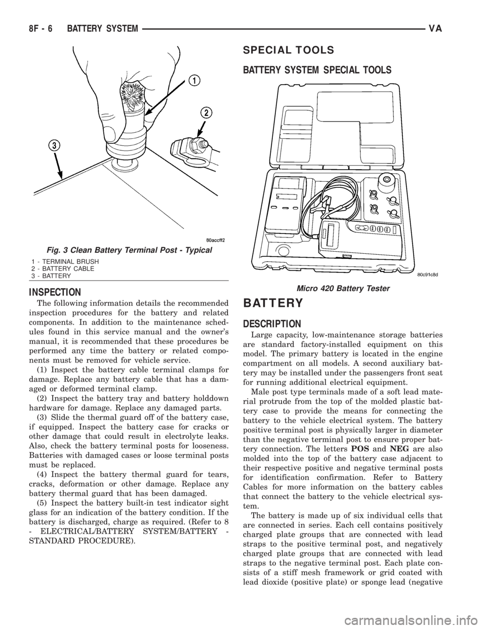
Fig. 3 Clean Battery Terminal Post - Typical
1 - TERMINAL BRUSH
2 - BATTERY CABLE
3 - BATTERY
Micro 420 Battery Tester
8F - 6 BATTERY SYSTEMVA
Page 883 of 2305
SPECIAL TOOLS
GENERATOR
DESCRIPTION
The generator is belt-driven by the engine using a
serpentine-type drive belt. It is serviced only as a
complete assembly. If the generator fails for any rea-
son, the entire assembly must be replaced.
On certain engines, the decoupler pulley may be
replaced separately.
OPERATION
As the energized rotor begins to rotate within the
generator, the spinning magnetic field induces a cur-
rent into the windings of the stator coil. Once the
generator begins producing sufficient current, it also
provides the current needed to energize the rotor.
The stator winding connections deliver the induced
AC current to 3 positive and 3 negative diodes for
rectification. From the diodes, rectified DC current isdelivered to the vehicle electrical system through the
generator battery terminal.
Although the generators appear the same exter-
nally, different generators with different output rat-
ings are used on this vehicle. Be certain that the
replacement generator has the same output rating
and part number as the original unit. Refer to Spec-
ifications and see Generator Ratings for amperage
ratings and part numbers.
Noise emitting from the generator may be caused
by: worn, loose or defective bearings; a loose or defec-
tive drive pulley (decoupler pulley); incorrect, worn,
damaged or misadjusted fan drive belt; loose mount-
ing bolts; a misaligned drive pulley or a defective sta-
tor or diode.
An instrument panel mounted, battery charge indi-
cator lamp is used. When the key is in the on posi-
tion, the lamp will be illuminated. This is done as a
bulb check. If this lamp remains illuminated while
the engine is running, a Diagnostic Trouble Code
(DTC) has been detected for the charging system.
REMOVAL
CAUTION: DISCONNECT NEGATIVE CABLE FROM
BATTERY BEFORE REMOVING BATTERY OUTPUT
WIRE FROM GENERATOR. FAILURE TO DO SO
CAN RESULT IN INJURY.
CAUTION: Never force a belt over a pulley rim
using a screwdriver. The synthetic fiber of the belt
can be damaged.
CAUTION: When installing a serpentine accessory
drive belt, the belt MUST be routed correctly. The
water pump will be rotating in the wrong direction if
the belt is installed incorrectly, causing the engine
to overheat. Refer to belt routing label in engine
compartment, or refer to Belt Schematics in Cooling
System.
(1) Disconnect and isolate negative battery cable.
(2) Remove generator drive belt. Refer to Cooling
System for procedure.
(3) Raise and support vehicle.
(4) Remove protective plastic cover from B+ stud
at top of generator.
(5) Remove nut securing battery output cable to
B+ terminal at top of generator.
(6) Unplug field terminal connector at rear of gen-
erator.
(7) Remove 4 generator mounting bolts (Torx-style
#12 bit) (Fig. 1).
(8) Remove generator from lower side of vehicle.
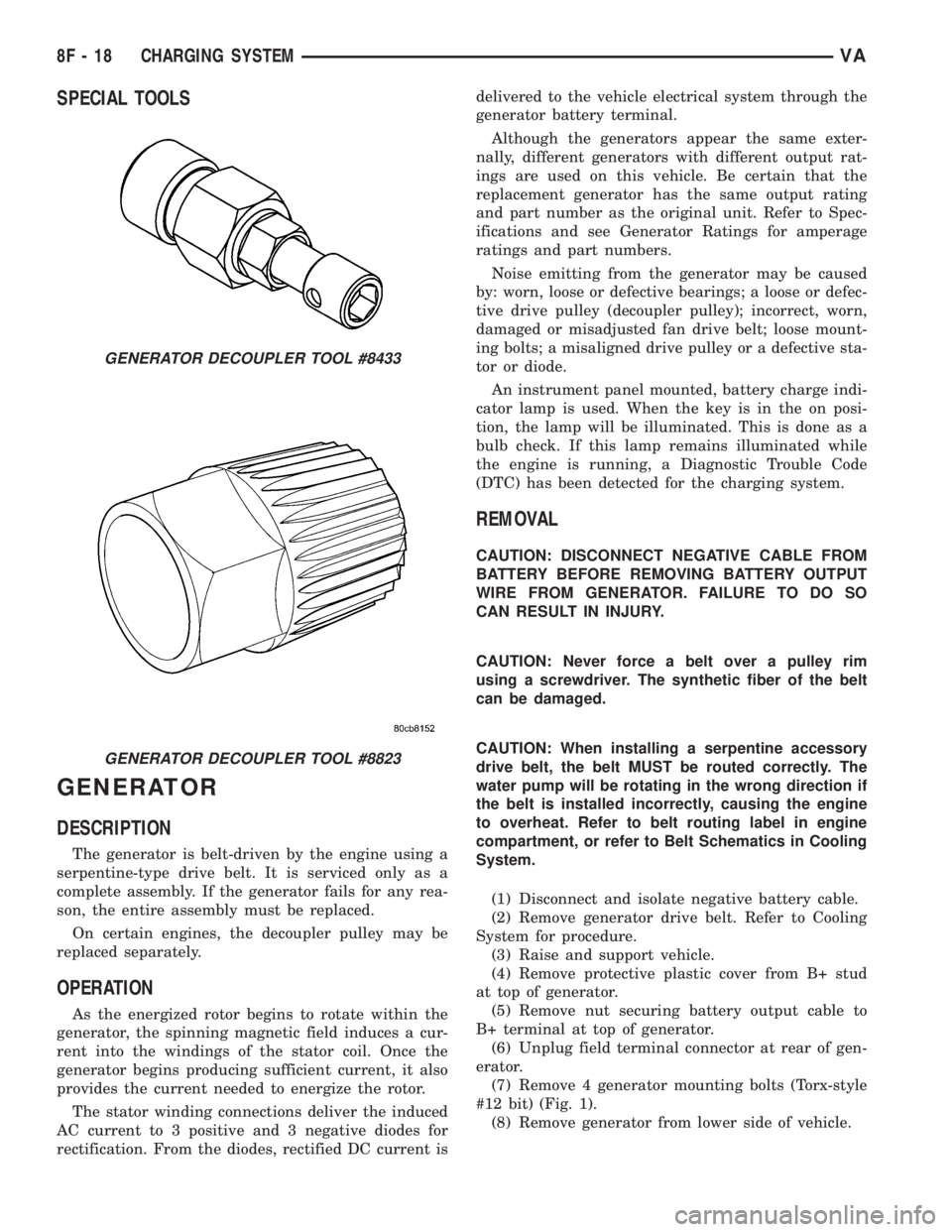
GENERATOR DECOUPLER TOOL #8433
GENERATOR DECOUPLER TOOL #8823
8F - 18 CHARGING SYSTEMVA
Page 884 of 2305
INSTALLATION
(1) Raise and support vehicle.
(2) Position generator to engine.
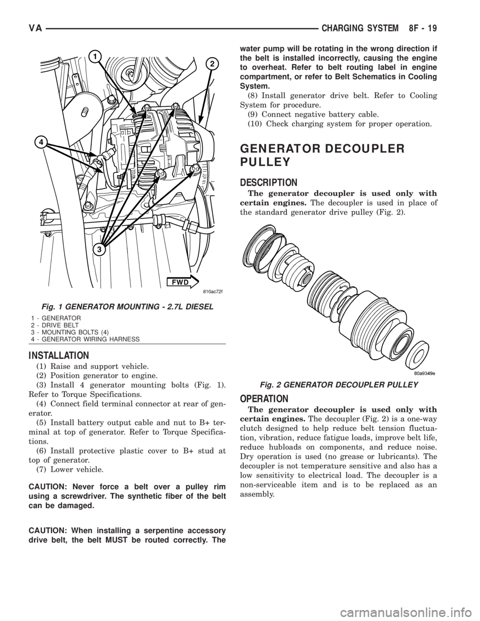
(3) Install 4 generator mounting bolts (Fig. 1).
Refer to Torque Specifications.
(4) Connect field terminal connector at rear of gen-
erator.
(5) Install battery output cable and nut to B+ ter-
minal at top of generator. Refer to Torque Specifica-
tions.
(6) Install protective plastic cover to B+ stud at
top of generator.
(7) Lower vehicle.
CAUTION: Never force a belt over a pulley rim
using a screwdriver. The synthetic fiber of the belt
can be damaged.
CAUTION: When installing a serpentine accessory
drive belt, the belt MUST be routed correctly. Thewater pump will be rotating in the wrong direction if
the belt is installed incorrectly, causing the engine
to overheat. Refer to belt routing label in engine
compartment, or refer to Belt Schematics in Cooling
System.
(8) Install generator drive belt. Refer to Cooling
System for procedure.
(9) Connect negative battery cable.
(10) Check charging system for proper operation.
GENERATOR DECOUPLER
PULLEY
DESCRIPTION
The generator decoupler is used only with
certain engines.The decoupler is used in place of
the standard generator drive pulley (Fig. 2).
OPERATION
The generator decoupler is used only with
certain engines.The decoupler (Fig. 2) is a one-way
clutch designed to help reduce belt tension fluctua-
tion, vibration, reduce fatigue loads, improve belt life,
reduce hubloads on components, and reduce noise.
Dry operation is used (no grease or lubricants). The
decoupler is not temperature sensitive and also has a
low sensitivity to electrical load. The decoupler is a
non-serviceable item and is to be replaced as an
assembly.
Fig. 1 GENERATOR MOUNTING - 2.7L DIESEL
1 - GENERATOR
2 - DRIVE BELT
3 - MOUNTING BOLTS (4)
4 - GENERATOR WIRING HARNESS
Fig. 2 GENERATOR DECOUPLER PULLEY
VACHARGING SYSTEM 8F - 19
Page 898 of 2305
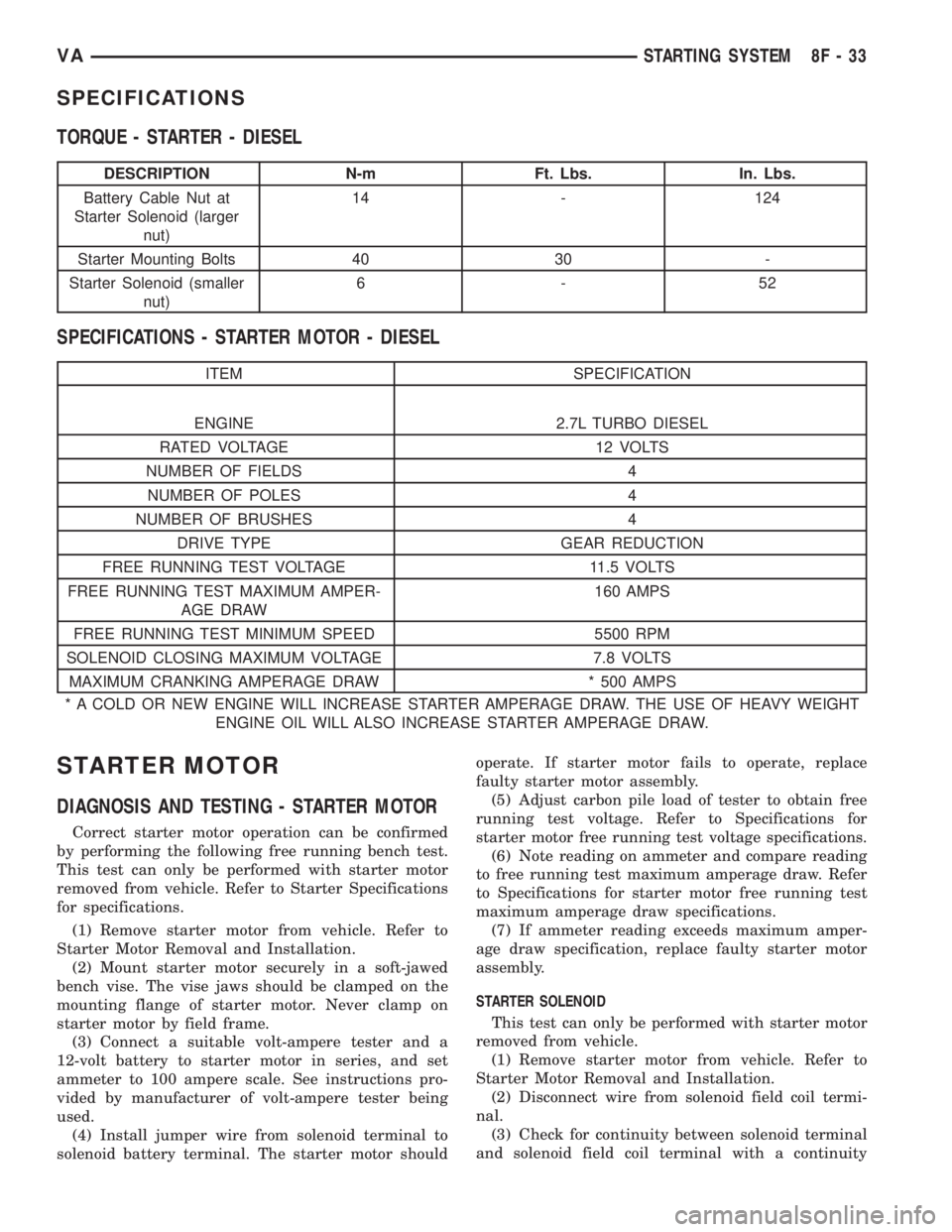
SPECIFICATIONS
TORQUE - STARTER - DIESEL
DESCRIPTION N-m Ft. Lbs. In. Lbs.
Battery Cable Nut at
Starter Solenoid (larger
nut)14 - 124
Starter Mounting Bolts 40 30 -
Starter Solenoid (smaller
nut)6-52
SPECIFICATIONS - STARTER MOTOR - DIESEL
ITEM SPECIFICATION
ENGINE 2.7L TURBO DIESEL
RATED VOLTAGE 12 VOLTS
NUMBER OF FIELDS 4
NUMBER OF POLES 4
NUMBER OF BRUSHES 4
DRIVE TYPE GEAR REDUCTION
FREE RUNNING TEST VOLTAGE 11.5 VOLTS
FREE RUNNING TEST MAXIMUM AMPER-
AGE DRAW160 AMPS
FREE RUNNING TEST MINIMUM SPEED 5500 RPM
SOLENOID CLOSING MAXIMUM VOLTAGE 7.8 VOLTS
MAXIMUM CRANKING AMPERAGE DRAW * 500 AMPS
* A COLD OR NEW ENGINE WILL INCREASE STARTER AMPERAGE DRAW. THE USE OF HEAVY WEIGHT
ENGINE OIL WILL ALSO INCREASE STARTER AMPERAGE DRAW.
STARTER MOTOR
DIAGNOSIS AND TESTING - STARTER MOTOR
Correct starter motor operation can be confirmed
by performing the following free running bench test.
This test can only be performed with starter motor
removed from vehicle. Refer to Starter Specifications
for specifications.
(1) Remove starter motor from vehicle. Refer to
Starter Motor Removal and Installation.
(2) Mount starter motor securely in a soft-jawed
bench vise. The vise jaws should be clamped on the
mounting flange of starter motor. Never clamp on
starter motor by field frame.
(3) Connect a suitable volt-ampere tester and a
12-volt battery to starter motor in series, and set
ammeter to 100 ampere scale. See instructions pro-
vided by manufacturer of volt-ampere tester being
used.
(4) Install jumper wire from solenoid terminal to
solenoid battery terminal. The starter motor shouldoperate. If starter motor fails to operate, replace
faulty starter motor assembly.
(5) Adjust carbon pile load of tester to obtain free
running test voltage. Refer to Specifications for
starter motor free running test voltage specifications.
(6) Note reading on ammeter and compare reading
to free running test maximum amperage draw. Refer
to Specifications for starter motor free running test
maximum amperage draw specifications.
(7) If ammeter reading exceeds maximum amper-
age draw specification, replace faulty starter motor
assembly.
STARTER SOLENOID
This test can only be performed with starter motor
removed from vehicle.
(1) Remove starter motor from vehicle. Refer to
Starter Motor Removal and Installation.
(2) Disconnect wire from solenoid field coil termi-
nal.
(3) Check for continuity between solenoid terminal
and solenoid field coil terminal with a continuity
VASTARTING SYSTEM 8F - 33
Page 899 of 2305
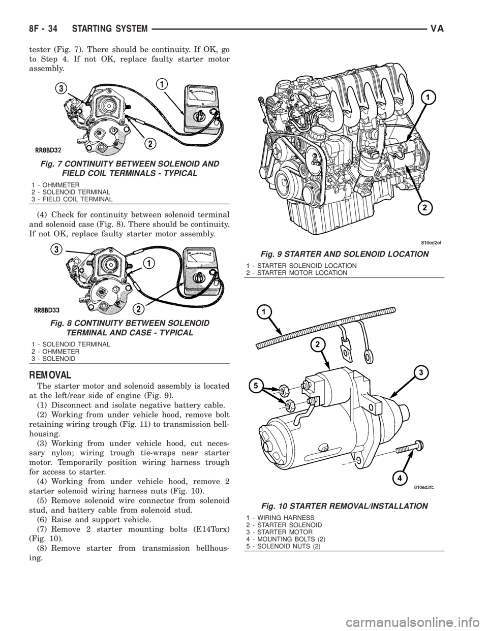
tester (Fig. 7). There should be continuity. If OK, go
to Step 4. If not OK, replace faulty starter motor
assembly.
(4) Check for continuity between solenoid terminal
and solenoid case (Fig. 8). There should be continuity.
If not OK, replace faulty starter motor assembly.
REMOVAL
The starter motor and solenoid assembly is located
at the left/rear side of engine (Fig. 9).
(1) Disconnect and isolate negative battery cable.
(2) Working from under vehicle hood, remove bolt
retaining wiring trough (Fig. 11) to transmission bell-
housing.
(3) Working from under vehicle hood, cut neces-
sary nylon; wiring trough tie-wraps near starter
motor. Temporarily position wiring harness trough
for access to starter.
(4) Working from under vehicle hood, remove 2
starter solenoid wiring harness nuts (Fig. 10).
(5) Remove solenoid wire connector from solenoid
stud, and battery cable from solenoid stud.
(6) Raise and support vehicle.
(7) Remove 2 starter mounting bolts (E14Torx)
(Fig. 10).
(8) Remove starter from transmission bellhous-
ing.
Fig. 7 CONTINUITY BETWEEN SOLENOID AND
FIELD COIL TERMINALS - TYPICAL
1 - OHMMETER
2 - SOLENOID TERMINAL
3 - FIELD COIL TERMINAL
Fig. 8 CONTINUITY BETWEEN SOLENOID
TERMINAL AND CASE - TYPICAL
1 - SOLENOID TERMINAL
2 - OHMMETER
3 - SOLENOID
Fig. 9 STARTER AND SOLENOID LOCATION
1 - STARTER SOLENOID LOCATION
2 - STARTER MOTOR LOCATION
Fig. 10 STARTER REMOVAL/INSTALLATION
1 - WIRING HARNESS
2 - STARTER SOLENOID
3 - STARTER MOTOR
4 - MOUNTING BOLTS (2)
5 - SOLENOID NUTS (2)
8F - 34 STARTING SYSTEMVA