2006 MERCEDES-BENZ SPRINTER check engine
[x] Cancel search: check enginePage 832 of 2305
ACCESSORY DRIVE
TABLE OF CONTENTS
page page
BELT TENSIONERS
DESCRIPTION..........................5
OPERATION............................5
DRIVE BELTS
DIAGNOSIS AND TESTING - ACCESSORY
DRIVE BELT..........................5REMOVAL
REMOVAL............................8
REMOVAL............................8
INSTALLATION
INSTALLATION........................8
INSTALLATION........................8
BELT TENSIONERS
DESCRIPTION
CAUTION: Do not attempt to check belt tension with
a belt tension gauge on vehicles equipped with an
automatic belt tensioner.
Drive belts on all engines are equipped with a
spring loaded automatic belt tensioner. This ten-
sioner maintains constant belt tension at all times
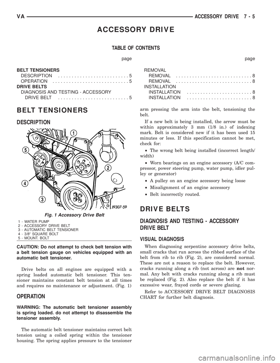
and requires no maintenance or adjustment. (Fig. 1)
OPERATION
WARNING: The automatic belt tensioner assembly
is spring loaded. do not attempt to disassemble the
tensioner assembly.
The automatic belt tensioner maintains correct belt
tension using a coiled spring within the tensioner
housing. The spring applies pressure to the tensionerarm pressing the arm into the belt, tensioning the
belt.
If a new belt is being installed, the arrow must be
within approximately 3 mm (1/8 in.) of indexing
mark. Belt is considered new if it has been used 15
minutes or less. If this specification cannot be met,
check for:
²The wrong belt being installed (incorrect length/
width)
²Worn bearings on an engine accessory (A/C com-
pressor, power steering pump, water pump, idler pul-
ley or generator)
²A pulley on an engine accessory being loose
²Misalignment of an engine accessory
²Belt incorrectly routed.
DRIVE BELTS
DIAGNOSIS AND TESTING - ACCESSORY
DRIVE BELT
VISUAL DIAGNOSIS
When diagnosing serpentine accessory drive belts,
small cracks that run across the ribbed surface of the
belt from rib to rib (Fig. 2), are considered normal.
These are not a reason to replace the belt. However,
cracks running along a rib (not across) arenotnor-
mal. Any belt with cracks running along a rib must
be replaced (Fig. 2). Also replace the belt if it has
excessive wear, frayed cords or severe glazing.
Refer to ACCESSORY DRIVE BELT DIAGNOSIS
CHART for further belt diagnosis.
Fig. 1 Accessory Drive Belt
1 - WATER PUMP
2 - ACCESSORY DRIVE BELT
3 - AUTOMATIC BELT TENSIONER
4 - 3/89SQUARE BOLT
5 - MOUNT. BOLT
VAACCESSORY DRIVE 7 - 5
Page 835 of 2305
REMOVAL
REMOVAL
CAUTION: Do not attempt to check belt tension with
a belt tension gauge on vehicles equipped with an
automatic belt tensioner.
NOTE: The belt routing schematics are published
from the latest information available at the time of
publication. If anything differs between these sche-
matics and the Belt Routing Label, use the sche-
matics on Belt Routing Label.This label is located in
the engine compartment.
(1) Remove A/C compressor drive belt (Refer to 7 -
COOLING/ACCESSORY DRIVE/DRIVE BELTS -
REMOVAL).
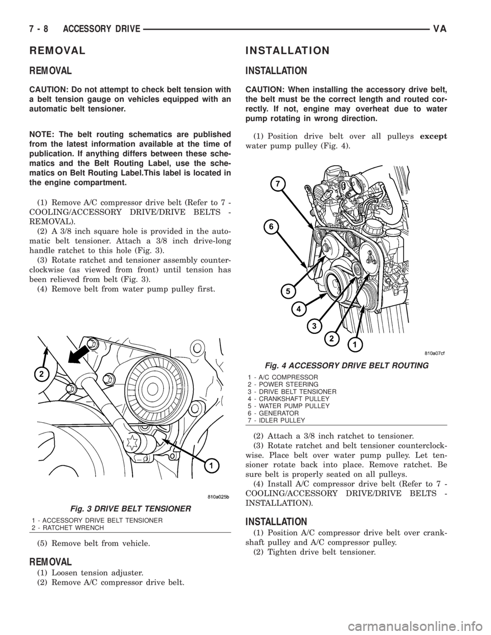
(2) A 3/8 inch square hole is provided in the auto-
matic belt tensioner. Attach a 3/8 inch drive-long
handle ratchet to this hole (Fig. 3).
(3) Rotate ratchet and tensioner assembly counter-
clockwise (as viewed from front) until tension has
been relieved from belt (Fig. 3).
(4) Remove belt from water pump pulley first.
(5) Remove belt from vehicle.
REMOVAL
(1) Loosen tension adjuster.
(2) Remove A/C compressor drive belt.
INSTALLATION
INSTALLATION
CAUTION: When installing the accessory drive belt,
the belt must be the correct length and routed cor-
rectly. If not, engine may overheat due to water
pump rotating in wrong direction.
(1) Position drive belt over all pulleysexcept
water pump pulley (Fig. 4).
(2) Attach a 3/8 inch ratchet to tensioner.
(3) Rotate ratchet and belt tensioner counterclock-
wise. Place belt over water pump pulley. Let ten-
sioner rotate back into place. Remove ratchet. Be
sure belt is properly seated on all pulleys.
(4) Install A/C compressor drive belt (Refer to 7 -
COOLING/ACCESSORY DRIVE/DRIVE BELTS -
INSTALLATION).
INSTALLATION
(1) Position A/C compressor drive belt over crank-
shaft pulley and A/C compressor pulley.
(2) Tighten drive belt tensioner.
Fig. 3 DRIVE BELT TENSIONER
1 - ACCESSORY DRIVE BELT TENSIONER
2 - RATCHET WRENCH
Fig. 4 ACCESSORY DRIVE BELT ROUTING
1 - A/C COMPRESSOR
2 - POWER STEERING
3 - DRIVE BELT TENSIONER
4 - CRANKSHAFT PULLEY
5 - WATER PUMP PULLEY
6 - GENERATOR
7 - IDLER PULLEY
7 - 8 ACCESSORY DRIVEVA
Page 837 of 2305
Propylene - glycol / Ethylene - glycol Mixtures - Should Not
Be Used in Chrysler Vehicles
Propylene-glycol/ethylene-glycol Mixtures can
cause the destabilization of various corrosion inhibi-
tors, causing damage to the various cooling system
components. Also, once ethylene-glycol and propy-
lene-glycol based coolants are mixed in the vehicle,
conventional methods of determining freeze point will
not be accurate. Both the refractive index and spe-
cific gravity differ between ethylene glycol and propy-
lene glycol.
CAUTION: Richer antifreeze mixtures cannot be
measured with normal field equipment and can
cause problems associated with 100 percent ethyl-
ene-glycol.
DIAGNOSIS AND TESTING
COOLING SYSTEM LEAKS
ULTRAVIOLET LIGHT METHOD
A leak detection additive is available through the
parts department that can be added to cooling sys-
tem. The additive is highly visible under ultraviolet
light (black light). Pour one ounce of additive into
cooling system. Place heater control unit in HEAT
position. Start and operate engine until radiator
upper hose is warm to touch. Aim the commercially
available black light tool at components to be
checked. If leaks are present, black light will cause
additive to glow a bright green color.
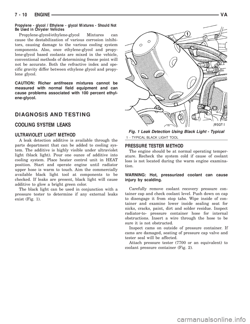
The black light can be used in conjunction with a
pressure tester to determine if any external leaks
exist (Fig. 1).
PRESSURE TESTER METHOD
The engine should be at normal operating temper-
ature. Recheck the system cold if cause of coolant
loss is not located during the warm engine examina-
tion.
WARNING: Hot, pressurized coolant can cause
injury by scalding.
Carefully remove coolant recovery pressure con-
tainer cap and check coolant level. Push down on cap
to disengage it from stop tabs. Wipe inside of con-
tainer and examine lower inside sealing seat for
nicks, cracks, paint, dirt and solder residue. Inspect
radiator-to- pressure container hose for internal
obstructions. Insert a wire through the hose to be
sure it is not obstructed.
Inspect cams on outside of pressure container. If
cams are damaged, seating of pressure cap valve and
tester seal will be affected.
Attach pressure tester (7700 or an equivalent) to
coolant pressure container (Fig. 2).
Fig. 1 Leak Detection Using Black Light - Typical
1 - TYPICAL BLACK LIGHT TOOL
7 - 10 ENGINEVA
Page 838 of 2305

Operate tester pump to apply 103.4 kPa (15 psi)
pressure to system. If hoses enlarge excessively or
bulges while testing, replace as necessary. Observe
gauge pointer and determine condition of cooling sys-
tem according to following criteria:
Holds Steady:If pointer remains steady for two
minutes, serious coolant leaks are not present in sys-
tem. However, there could be an internal leak that
does not appear with normal system test pressure. If
it is certain that coolant is being lost and leaks can-
not be detected, inspect for interior leakage or per-
form Internal Leakage Test.
Drops Slowly:Indicates a small leak or seepage
is occurring. Examine all connections for seepage or
slight leakage with a flashlight. Inspect radiator,
hoses, gasket edges and heater. Seal small leak holes
with a Sealer Lubricant (or equivalent). Repair leak
holes and inspect system again with pressure
applied.
Drops Quickly:Indicates that serious leakage is
occurring. Examine system for external leakage. If
leaks are not visible, inspect for internal leakage.
Large radiator leak holes should be repaired by a
reputable radiator repair shop.
INTERNAL LEAKAGE INSPECTION
Remove engine oil pan drain plug and drain a
small amount of engine oil. If coolant is present in
the pan, it will drain first because it is heavier than
oil. An alternative method is to operate engine for a
short period to churn the oil. After this is done,
remove engine dipstick and inspect for water glob-ules. Also inspect transmission dipstick for water
globules and transmission fluid cooler for leakage.
WARNING: WITH RADIATOR PRESSURE TESTER
TOOL INSTALLED ON RADIATOR, DO NOT ALLOW
PRESSURE TO EXCEED 110 KPA (20 PSI). PRES-
SURE WILL BUILD UP QUICKLY IF A COMBUSTION
LEAK IS PRESENT. TO RELEASE PRESSURE,
ROCK TESTER FROM SIDE TO SIDE. WHEN
REMOVING TESTER, DO NOT TURN TESTER MORE
THAN 1/2 TURN IF SYSTEM IS UNDER PRESSURE.
Operate engine without pressure cap on coolant
container until thermostat opens. Attach a Pressure
Tester to container. If pressure builds up quickly it
indicates a combustion leak exists. This is usually
the result of a cylinder head gasket leak or crack in
engine. Repair as necessary.
If there is not an immediate pressure increase,
pump the Pressure Tester. Do this until indicated
pressure is within system range of 110 kPa (16 psi).
Fluctuation of gauge pointer indicates compression or
combustion leakage into cooling system.
Because the vehicle is equipped with a catalytic
converter,do notremove spark plug cables or short
out cylinders to isolate compression leak.
If the needle on dial of pressure tester does not
fluctuate, race engine a few times to check for an
abnormal amount of coolant or steam. This would be
emitting from exhaust pipe. Coolant or steam from
exhaust pipe may indicate a faulty cylinder head gas-
ket, cracked engine cylinder block or cylinder head.
A convenient check for exhaust gas leakage into
cooling system is provided by a commercially avail-
able Block Leak Check tool. Follow manufacturers
instructions when using this product.
COMBUSTION LEAKAGE TEST - WITHOUT PRES-
SURE TESTER
DO NOT WASTE reusable coolant. If solution is
clean, drain coolant into a clean and suitably marked
container for reuse.
WARNING: Do not remove cylinder block drain
plugs or loosen radiator drain with system hot and
under pressure. serious burns from coolant can
occur.
Drain sufficient coolant to allow thermostat
removal.
Remove accessory drive belt.
Add coolant to pressure container to bring level to
within 6.3 mm (1/4 in) of top of thermostat housing.
CAUTION: Avoid overheating. Do not operate
engine for an excessive period of time. Open drain-
cock immediately after test to eliminate boil over.
Fig. 2 PRESSURE TESTING
1 - PRESSURE RESERVOIR CAP
2 - PRESSURE RESERVOIR
3 - PRESSURE TESTER
VAENGINE 7 - 11
Page 846 of 2305

(17) Take off charge air cooler together with cool-
ing loop of the steering at the radiator (Fig. 10).
(18) Remove bottom radiator trim (Fig. 10).
(19) Detach coolant hose at radiator.
(20) Detach coolant pipe together with coolant
hose at the fan shroud.
(21) Remove radiator fan shroud (Fig. 10).
INSTALLATION
(1) Install fan shroud to radiator (Fig. 10).
(2) Attach coolant pipe with hoses to fan shroud
(Fig. 10).
(3) Attach coolant hose at radiator (Fig. 10).
(4) Install bottom radiator trim (Fig. 10).
(5) Install charge air cooler along with cooling loop
of the power steering, to radiator (Fig. 10).
(6) Install radiator assembly into the rubber grom-
mets (Fig. 9).
(7) Install both right and left side radiator trim
panels (Fig. 9).
(8) Attach the transmission cooler lines (Fig. 9).
(9) Attach coolant hose to the bottom right of the
radiator (Fig. 9).
(10) Attach both power steering hydraulic lines
(Fig. 9).
(11) Connect coolant level sensor electrical connec-
tor (Fig. 9).
(12) Connect coolant hoses to the coolant reservoir,
radiator and water pump (Fig. 9).(13) Attach air intake pipe at the body.
(14) Attach charge air hose at air intake.
(15) Attach charge air hose at turbocharger.
(16) Install A/C condenser.
(17) Install front bumper.
(18) Install front end cross member.
(19) Refill power steering to proper level.
(20) Refill transmission to proper level.
(21) Close radiator drain plug and refill the cooling
system (Refer to 7 - COOLING/ENGINE/COOLANT -
STANDARD PROCEDURE).
(22) Recharge air conditioning (Refer to 24 -
HEATING & AIR CONDITIONING/PLUMBING -
STANDARD PROCEDURE).
(23) Run engine until warm and check for leaks.
RADIATOR PRESSURE CAP
DESCRIPTION
All vehicles are equipped with a pressure cap (Fig.
11). This cap releases pressure at some point within
a range of 124-145 kPa (18-21 psi). The pressure
relief point (in pounds) is engraved on top of the cap
The cooling system will operate at pressures
slightly above atmospheric pressure. This results in a
higher coolant boiling point allowing increased radi-
ator cooling capacity. The cap contains a spring-
loaded pressure relief valve. This valve opens when
system pressure reaches the release range of 124-145
kPa (18-21 psi).
A rubber gasket seals the radiator filler neck. This
is done to maintain vacuum during coolant cool-down
and to prevent leakage when system is under pres-
sure.
Fig. 10 RADIATOR AND FAN SHROUD
1 - CLIP
2 - SHROUD
3 - RADIATOR
4 - BOTTOM RADIATOR TRIM PANEL
5 - CHARGE AIR COOLER
6 - TOP RADIATOR TRIM PANEL
7 - POWER STEERING COOLER LOOP
VAENGINE 7 - 19
Page 847 of 2305
OPERATION
A vent valve in the center of the cap will remain
shut as long as the cooling system is pressurized. As
the coolant cools, it contracts and creates a vacuum
in cooling system. This causes the vacuum valve to
open and coolant in reserve/overflow tank to be
drawn through connecting hose into radiator. If the
vacuum valve is stuck shut, or overflow hose is
kinked, radiator hoses will collapse on cool-down.
DIAGNOSIS AND TESTING - RADIATOR PRES-
SURE CAP
Remove cap from radiator. Be sure that sealing
surfaces are clean. Moisten rubber gasket with water
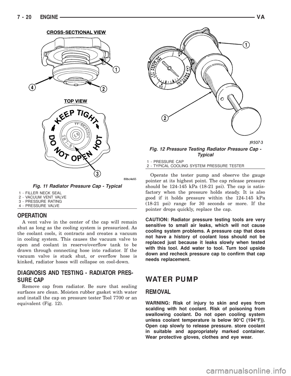
and install the cap on pressure tester Tool 7700 or an
equivalent (Fig. 12).Operate the tester pump and observe the gauge
pointer at its highest point. The cap release pressure
should be 124-145 kPa (18-21 psi). The cap is satis-
factory when the pressure holds steady. It is also
good if it holds pressure within the 124-145 kPa
(18-21 psi) range for 30 seconds or more. If the
pointer drops quickly, replace the cap.
CAUTION: Radiator pressure testing tools are very
sensitive to small air leaks, which will not cause
cooling system problems. A pressure cap that does
not have a history of coolant loss should not be
replaced just because it leaks slowly when tested
with this tool. Add water to tool. Turn tool upside
down and recheck pressure cap to confirm that cap
needs replacement.
WATER PUMP
REMOVAL
WARNING: Risk of injury to skin and eyes from
scalding with hot coolant. Risk of poisoning from
swallowing coolant. Do not open cooling system
unless coolant temperature is below 90ÉC (194ÉF)).
Open cap slowly to release pressure. store coolant
in suitable and appropriately marked container.
Wear protective gloves, clothes and eye wear.
Fig. 11 Radiator Pressure Cap - Typical
1 - FILLER NECK SEAL
2 - VACUUM VENT VALVE
3 - PRESSURE RATING
4 - PRESSURE VALVE
Fig. 12 Pressure Testing Radiator Pressure Cap -
Typical
1 - PRESSURE CAP
2 - TYPICAL COOLING SYSTEM PRESSURE TESTER
7 - 20 ENGINEVA
Page 849 of 2305
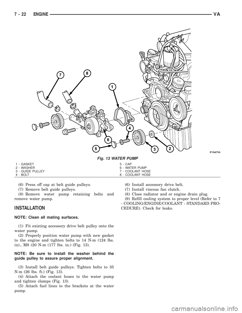
(6) Press off cap at belt guide pulleys.
(7) Remove belt guide pulleys.
(8) Remove water pump retaining bolts and
remove water pump.
INSTALLATION
NOTE: Clean all mating surfaces.
(1) Fit existing accessory drive belt pulley onto the
water pump.
(2) Properly position water pump with new gasket
to the engine and tighten bolts to 14 N´m (124 lbs.
in)., M8 (20 N´m (177 lbs. in.) (Fig. 13).
NOTE: Be sure to install the washer behind the
guide pulley to assure proper alignment.
(3) Install belt guide pulleys. Tighten bolts to 35
N´m (26 lbs. ft.) (Fig. 13).
(4) Attach the coolant hoses to the water pump
and tighten clamps (Fig. 13).
(5) Attach fuel lines to the brackets at the water
pump.(6) Install accessory drive belt.
(7) Install viscous fan clutch.
(8) Close radiator and or engine drain plug.
(9) Refill cooling system to proper level (Refer to 7
- COOLING/ENGINE/COOLANT - STANDARD PRO-
CEDURE). Check for leaks.
Fig. 13 WATER PUMP
1 - GASKET 5 - CAP
2 - WASHER 6 - WATER PUMP
3 - GUIDE PULLEY 7 - COOLANT HOSE
4 - BOLT 8 - COOLANT HOSE
7 - 22 ENGINEVA
Page 857 of 2305
actuators.These outputs allow the CTM the ability to
control numerous accessory systems in the vehicle.
The CTM monitors its own internal circuitry as
well as many of its input and output circuits, and
will store a Diagnostic Trouble Code (DTC) in elec-
tronic memory for any failure it detects. These DTCs
can be retrieved and diagnosed using a DRBIIItscan
tool. Refer to the appropriate diagnostic information.
HARD WIRED INPUTS
The hard wired inputs to the CTM include the fol-
lowing:
²Fused B(+)
²Fused ignition switch output (run-acc)
²Fused ignition switch output (run-start)
²Ground
²Key-in ignition switch sense
²Sliding door switch sense
²Passenger door switch sense
²Driver door switch sense
²PCI bus circuit
HARD WIRED OUTPUTS
The hard wired outputs of the CTM include the fol-
lowing:
²Door lock relay output
²Door unlock relay output
²VTSS indicator driver
MESSAGING
The CTM uses the following messages received
from other electronic modules over the PCI data bus:
²Airbag Deploy (ACM)
²Beep request (CMTC)
²Charging System Failure (PCM)
²Chime request (EMIC)
²Engine RPM (PCM)
²OK to Arm VTSS (PCM)
²Security indicator request (SKIM)
²System Voltage (PCM)
²Valid/Invalid Key (SKIM)
²Vehicle Distance (PCM)
²Vehicle Speed (PCM)
DIAGNOSIS AND TESTING - CENTRAL TIMER
MODULE
WARNING: To avoid personal injury or death, on
vehicles equipped with airbags, disable the supple-
mental restraint system before attempting any
steering wheel, steering column, airbag, seat belt
tensioner, or instrument panel component diagno-
sis or service. Disconnect and isolate the battery
negative (ground) cable, then wait two minutes for
the system capacitor to discharge before perform-
ing further diagnosis or service. This is the only
sure way to disable the supplemental restraint sys-tem. Failure to take the proper precautions could
result in accidental airbag deployment.
The hard wired inputs to and outputs from the
central timer module (CTM) may be diagnosed and
tested using conventional diagnostic tools and meth-
ods. Refer to the appropriate wiring information.
However, conventional diagnostic methods may not
prove conclusive in the diagnosis of the CTM. In
order to obtain conclusive testing of the CTM, the
programmable communications interface (PCI) data
bus network and all of the modules that provide
inputs to or receive outputs from the CTM must also
be checked. The most reliable, efficient, and accurate
means to diagnose the CTM, the PCI data bus net-
work, and the modules that provide inputs to, or
receive outputs from, the CTM requires the use of a
DRBIIItscan tool. Refer to the appropriate diagnos-
tic information.
REMOVAL
(1) Disconnect and isolate the battery negative
cable.
(2) Slide the driver seat to the full forward posi-
tion.
(3) Disconnect the wire harness connector for the
seat belt latch. (Fig. 1).
(4) Remove the screws that secure the closeout
panel beneathe the driver seat cushion and remove
the panel.
(5) Remove the screws that secure the central
timer module to the bracket.
(6) Disconnect the wire harness connectors from
the central timer module.
(7) Remove the central timer module from the
vehicle.
8E - 2 ELECTRONIC CONTROL MODULESVA