2006 MERCEDES-BENZ SPRINTER check engine
[x] Cancel search: check enginePage 707 of 2305
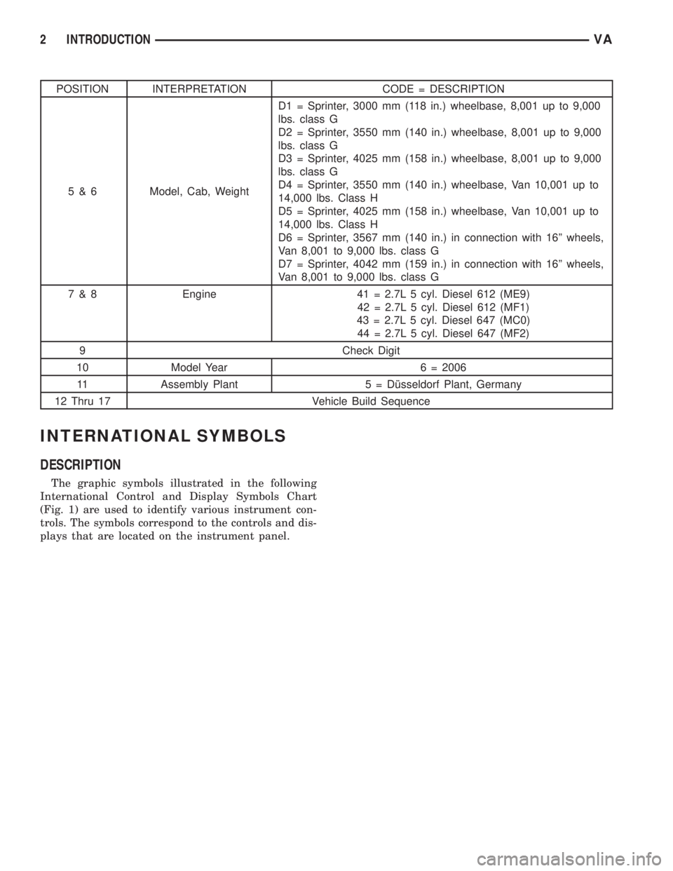
POSITION INTERPRETATION CODE = DESCRIPTION
5 & 6 Model, Cab, WeightD1 = Sprinter, 3000 mm (118 in.) wheelbase, 8,001 up to 9,000
lbs. class G
D2 = Sprinter, 3550 mm (140 in.) wheelbase, 8,001 up to 9,000
lbs. class G
D3 = Sprinter, 4025 mm (158 in.) wheelbase, 8,001 up to 9,000
lbs. class G
D4 = Sprinter, 3550 mm (140 in.) wheelbase, Van 10,001 up to
14,000 lbs. Class H
D5 = Sprinter, 4025 mm (158 in.) wheelbase, Van 10,001 up to
14,000 lbs. Class H
D6 = Sprinter, 3567 mm (140 in.) in connection with 16º wheels,
Van 8,001 to 9,000 lbs. class G
D7 = Sprinter, 4042 mm (159 in.) in connection with 16º wheels,
Van 8,001 to 9,000 lbs. class G
7 & 8 Engine 41 = 2.7L 5 cyl. Diesel 612 (ME9)
42 = 2.7L 5 cyl. Diesel 612 (MF1)
43 = 2.7L 5 cyl. Diesel 647 (MC0)
44 = 2.7L 5 cyl. Diesel 647 (MF2)
9 Check Digit
10 Model Year 6 = 2006
11 Assembly Plant 5 = Dîsseldorf Plant, Germany
12 Thru 17 Vehicle Build Sequence
INTERNATIONAL SYMBOLS
DESCRIPTION
The graphic symbols illustrated in the following
International Control and Display Symbols Chart
(Fig. 1) are used to identify various instrument con-
trols. The symbols correspond to the controls and dis-
plays that are located on the instrument panel.
2 INTRODUCTIONVA
Page 716 of 2305
LUBRICATION & MAINTENANCE
TABLE OF CONTENTS
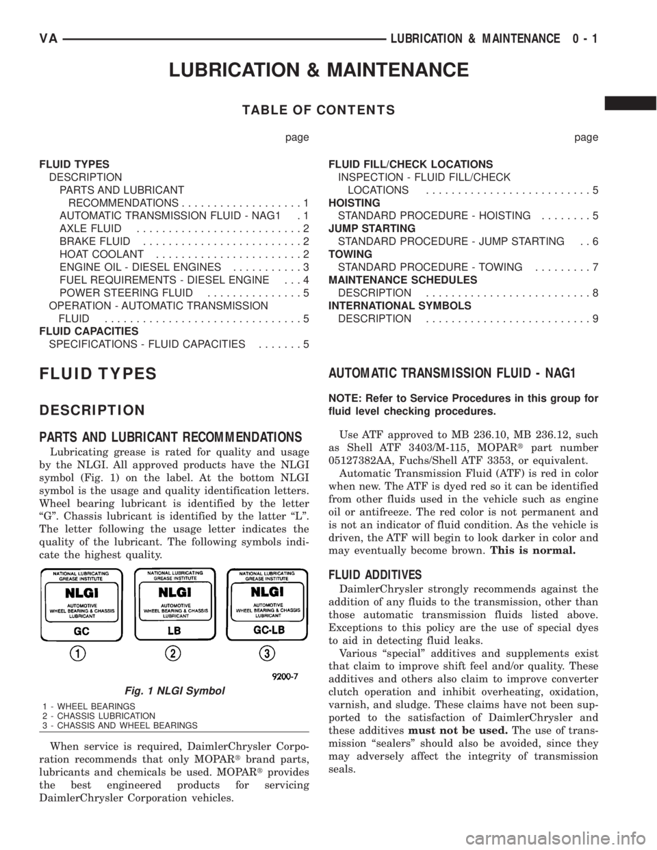
page page
FLUID TYPES
DESCRIPTION
PARTS AND LUBRICANT
RECOMMENDATIONS...................1
AUTOMATIC TRANSMISSION FLUID - NAG1 . 1
AXLE FLUID..........................2
BRAKE FLUID.........................2
HOAT COOLANT.......................2
ENGINE OIL - DIESEL ENGINES...........3
FUEL REQUIREMENTS - DIESEL ENGINE . . . 4
POWER STEERING FLUID...............5
OPERATION - AUTOMATIC TRANSMISSION
FLUID...............................5
FLUID CAPACITIES
SPECIFICATIONS - FLUID CAPACITIES.......5FLUID FILL/CHECK LOCATIONS
INSPECTION - FLUID FILL/CHECK
LOCATIONS..........................5
HOISTING
STANDARD PROCEDURE - HOISTING........5
JUMP STARTING
STANDARD PROCEDURE - JUMP STARTING . . 6
TOWING
STANDARD PROCEDURE - TOWING.........7
MAINTENANCE SCHEDULES
DESCRIPTION..........................8
INTERNATIONAL SYMBOLS
DESCRIPTION..........................9
FLUID TYPES
DESCRIPTION
PARTS AND LUBRICANT RECOMMENDATIONS
Lubricating grease is rated for quality and usage
by the NLGI. All approved products have the NLGI
symbol (Fig. 1) on the label. At the bottom NLGI
symbol is the usage and quality identification letters.
Wheel bearing lubricant is identified by the letter
ªGº. Chassis lubricant is identified by the latter ªLº.
The letter following the usage letter indicates the
quality of the lubricant. The following symbols indi-
cate the highest quality.
When service is required, DaimlerChrysler Corpo-
ration recommends that only MOPARtbrand parts,
lubricants and chemicals be used. MOPARtprovides
the best engineered products for servicing
DaimlerChrysler Corporation vehicles.
AUTOMATIC TRANSMISSION FLUID - NAG1
NOTE: Refer to Service Procedures in this group for
fluid level checking procedures.
Use ATF approved to MB 236.10, MB 236.12, such
as Shell ATF 3403/M-115, MOPARtpart number
05127382AA, Fuchs/Shell ATF 3353, or equivalent.
Automatic Transmission Fluid (ATF) is red in color
when new. The ATF is dyed red so it can be identified
from other fluids used in the vehicle such as engine
oil or antifreeze. The red color is not permanent and
is not an indicator of fluid condition. As the vehicle is
driven, the ATF will begin to look darker in color and
may eventually become brown.This is normal.
FLUID ADDITIVES
DaimlerChrysler strongly recommends against the
addition of any fluids to the transmission, other than
those automatic transmission fluids listed above.
Exceptions to this policy are the use of special dyes
to aid in detecting fluid leaks.
Various ªspecialº additives and supplements exist
that claim to improve shift feel and/or quality. These
additives and others also claim to improve converter
clutch operation and inhibit overheating, oxidation,
varnish, and sludge. These claims have not been sup-
ported to the satisfaction of DaimlerChrysler and
these additivesmust not be used.The use of trans-
mission ªsealersº should also be avoided, since they
may adversely affect the integrity of transmission
seals.
Fig. 1 NLGI Symbol
1 - WHEEL BEARINGS
2 - CHASSIS LUBRICATION
3 - CHASSIS AND WHEEL BEARINGS
VALUBRICATION & MAINTENANCE 0 - 1
Page 720 of 2305
Do not blend other specific fuel additives with die-
sel fuel. They only result in unnecessary cost, and
may be harmful to the engine operation.
POWER STEERING FLUID
No fluid service required. Filled with Power Steer-
ing Fluid approved to MB 236.3, such as Mobil
ATF-D (Exxon Mobil Corporation) or equivalent.
OPERATION - AUTOMATIC TRANSMISSION
FLUID
The automatic transmission fluid is selected based
upon several qualities. The fluid must provide a high
level of protection for the internal components by
providing a lubricating film between adjacent metal
components. The fluid must also be thermally stable
so that it can maintain a consistent viscosity through
a large temperature range. If the viscosity stays con-
stant through the temperature range of operation,
transmission operation and shift feel will remain con-
sistent. Transmission fluid must also be a good con-
ductor of heat. The fluid must absorb heat from the
internal transmission components and transfer that
heat to the transmission case.
FLUID CAPACITIES
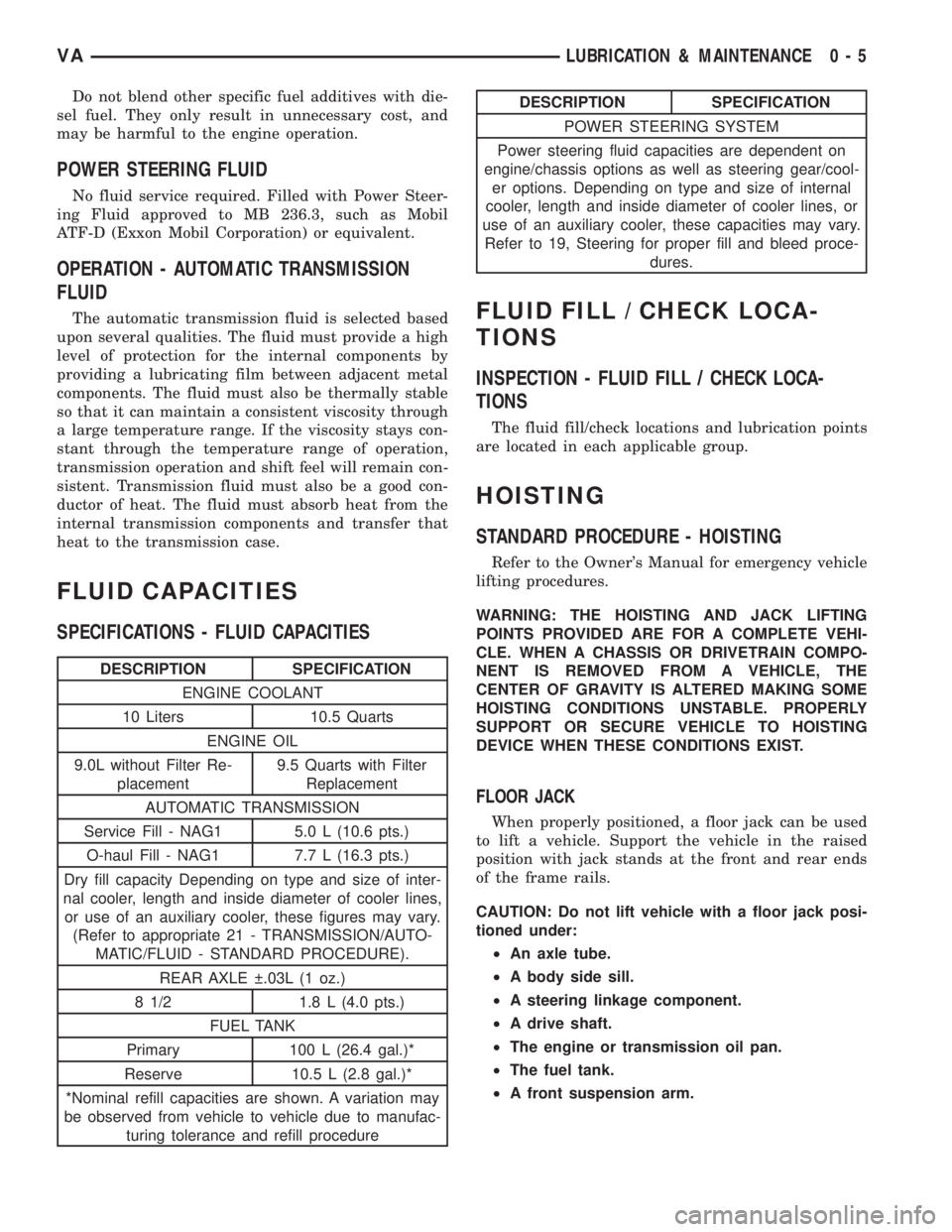
SPECIFICATIONS - FLUID CAPACITIES
DESCRIPTION SPECIFICATION
ENGINE COOLANT
10 Liters 10.5 Quarts
ENGINE OIL
9.0L without Filter Re-
placement9.5 Quarts with Filter
Replacement
AUTOMATIC TRANSMISSION
Service Fill - NAG1 5.0 L (10.6 pts.)
O-haul Fill - NAG1 7.7 L (16.3 pts.)
Dry fill capacity Depending on type and size of inter-
nal cooler, length and inside diameter of cooler lines,
or use of an auxiliary cooler, these figures may vary.
(Refer to appropriate 21 - TRANSMISSION/AUTO-
MATIC/FLUID - STANDARD PROCEDURE).
REAR AXLE .03L (1 oz.)
8 1/2 1.8 L (4.0 pts.)
FUEL TANK
Primary 100 L (26.4 gal.)*
Reserve 10.5 L (2.8 gal.)*
*Nominal refill capacities are shown. A variation may
be observed from vehicle to vehicle due to manufac-
turing tolerance and refill procedure
DESCRIPTION SPECIFICATION
POWER STEERING SYSTEM
Power steering fluid capacities are dependent on
engine/chassis options as well as steering gear/cool-
er options. Depending on type and size of internal
cooler, length and inside diameter of cooler lines, or
use of an auxiliary cooler, these capacities may vary.
Refer to 19, Steering for proper fill and bleed proce-
dures.
FLUID FILL / CHECK LOCA-
TIONS
INSPECTION - FLUID FILL / CHECK LOCA-
TIONS
The fluid fill/check locations and lubrication points
are located in each applicable group.
HOISTING
STANDARD PROCEDURE - HOISTING
Refer to the Owner's Manual for emergency vehicle
lifting procedures.
WARNING: THE HOISTING AND JACK LIFTING
POINTS PROVIDED ARE FOR A COMPLETE VEHI-
CLE. WHEN A CHASSIS OR DRIVETRAIN COMPO-
NENT IS REMOVED FROM A VEHICLE, THE
CENTER OF GRAVITY IS ALTERED MAKING SOME
HOISTING CONDITIONS UNSTABLE. PROPERLY
SUPPORT OR SECURE VEHICLE TO HOISTING
DEVICE WHEN THESE CONDITIONS EXIST.
FLOOR JACK
When properly positioned, a floor jack can be used
to lift a vehicle. Support the vehicle in the raised
position with jack stands at the front and rear ends
of the frame rails.
CAUTION: Do not lift vehicle with a floor jack posi-
tioned under:
²An axle tube.
²A body side sill.
²A steering linkage component.
²A drive shaft.
²The engine or transmission oil pan.
²The fuel tank.
²A front suspension arm.
VALUBRICATION & MAINTENANCE 0 - 5
Page 723 of 2305
effect panels. If necessary, remove the wheels from
the lifted end of the vehicle and lower the vehicle
closer to the ground, to increase the ground clearance
at the opposite end of the vehicle. Install lug nuts on
wheel attaching studs to retain brake drums.
RAMP ANGLE
If a vehicle with flat-bed towing equipment is used,
the approach ramp angle should not exceed 15
degrees.
TOWING WHEN KEYS ARE NOT AVAILABLE
When the vehicle is locked and keys are not avail-
able, use a flat bed hauler. A Wheel-lift or Sling-type
device can be used provided all the wheels are lifted
off the ground using tow dollies.
MAINTENANCE SCHEDULES
DESCRIPTION
The use of special lubricant additives is not recom-
mended. The use of such additives may affect the
warranty rights. With regard to legal stipulations
concerning emissions control, please note that
engines have to be serviced and adjusted in accor-
dance with special instructions and using special
measuring equipment. Modifications to or interfer-
ence with the emissions control systems are not per-
missible.
MAINTENANCE - WITHOUT ASSYST MAINTE-
NANCE COMPUTER
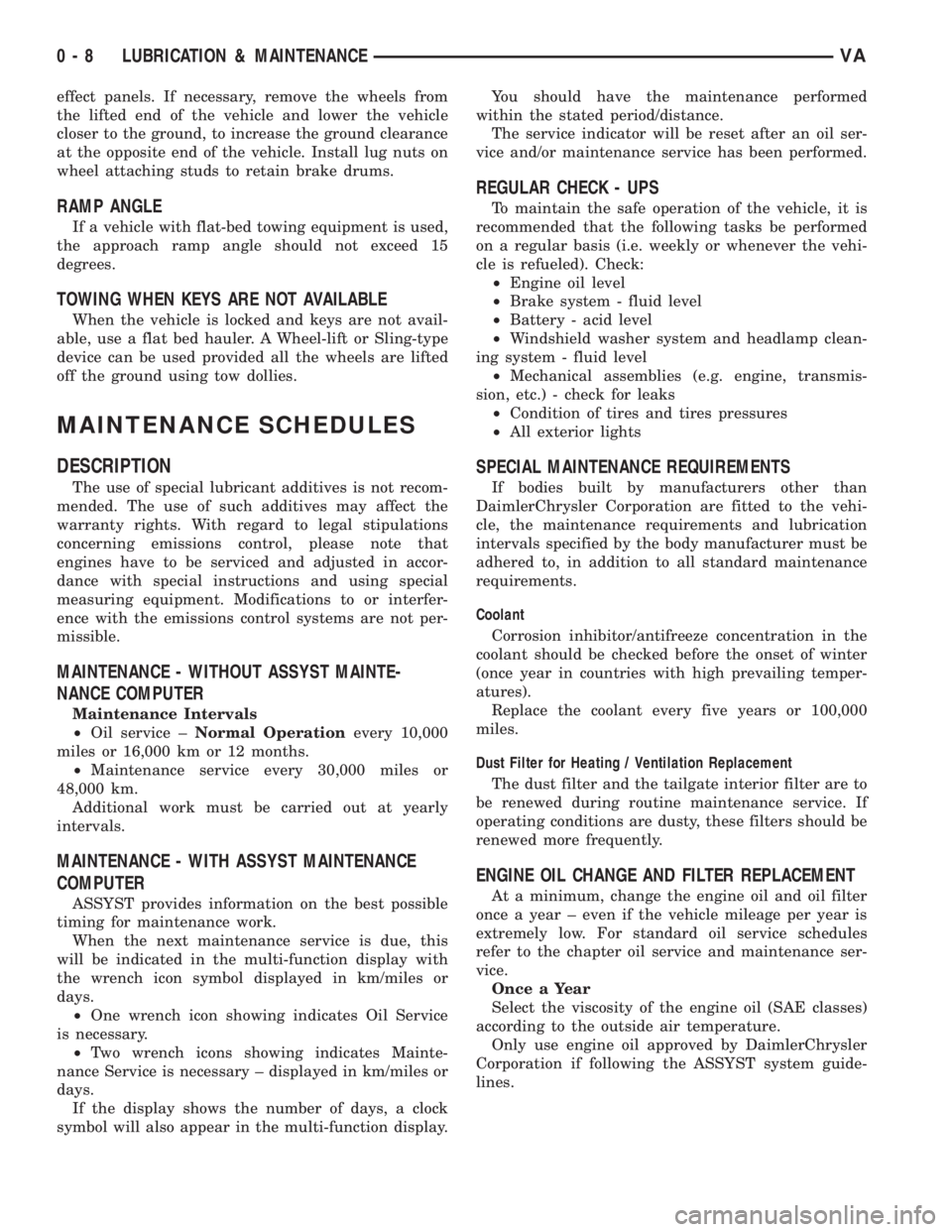
Maintenance Intervals
²Oil service ±Normal Operationevery 10,000
miles or 16,000 km or 12 months.
²Maintenance service every 30,000 miles or
48,000 km.
Additional work must be carried out at yearly
intervals.
MAINTENANCE - WITH ASSYST MAINTENANCE
COMPUTER
ASSYST provides information on the best possible
timing for maintenance work.
When the next maintenance service is due, this
will be indicated in the multi-function display with
the wrench icon symbol displayed in km/miles or
days.
²One wrench icon showing indicates Oil Service
is necessary.
²Two wrench icons showing indicates Mainte-
nance Service is necessary ± displayed in km/miles or
days.
If the display shows the number of days, a clock
symbol will also appear in the multi-function display.You should have the maintenance performed
within the stated period/distance.
The service indicator will be reset after an oil ser-
vice and/or maintenance service has been performed.
REGULAR CHECK - UPS
To maintain the safe operation of the vehicle, it is
recommended that the following tasks be performed
on a regular basis (i.e. weekly or whenever the vehi-
cle is refueled). Check:
²Engine oil level
²Brake system - fluid level
²Battery - acid level
²Windshield washer system and headlamp clean-
ing system - fluid level
²Mechanical assemblies (e.g. engine, transmis-
sion, etc.) - check for leaks
²Condition of tires and tires pressures
²All exterior lights
SPECIAL MAINTENANCE REQUIREMENTS
If bodies built by manufacturers other than
DaimlerChrysler Corporation are fitted to the vehi-
cle, the maintenance requirements and lubrication
intervals specified by the body manufacturer must be
adhered to, in addition to all standard maintenance
requirements.
Coolant
Corrosion inhibitor/antifreeze concentration in the
coolant should be checked before the onset of winter
(once year in countries with high prevailing temper-
atures).
Replace the coolant every five years or 100,000
miles.
Dust Filter for Heating / Ventilation Replacement
The dust filter and the tailgate interior filter are to
be renewed during routine maintenance service. If
operating conditions are dusty, these filters should be
renewed more frequently.
ENGINE OIL CHANGE AND FILTER REPLACEMENT
At a minimum, change the engine oil and oil filter
once a year ± even if the vehicle mileage per year is
extremely low. For standard oil service schedules
refer to the chapter oil service and maintenance ser-
vice.
Once a Year
Select the viscosity of the engine oil (SAE classes)
according to the outside air temperature.
Only use engine oil approved by DaimlerChrysler
Corporation if following the ASSYST system guide-
lines.
0 - 8 LUBRICATION & MAINTENANCEVA
Page 724 of 2305

SCOPE OF WORK FOR MAINTENANCE SERVICE
Oil Service
²Engine: Oil change and filter replacement
Check fluid levels of the following system, refill as neces-
sary.
²If fluid is lost, trace and eliminate cause - as a
separate order.
²Power-assisted steering
Lubrication work:
²Trailer tow hitch (original equipment)
Maintenance
²ASSYST maintenance computer reset
Function check
²Signalling system, warning and indicator lamps
²Headlamps, exterior lighting
²Windshield wipers, windshield washer system
Check for leaks and damage
²Check for abrasion points and ensure that lines
are correctly routed!
²All lines and hoses, sensor cables
²Rubber boots on front axle drive shafts, rubber
boots on front axle suspension ball joints, shock
absorbers
²Check fluid levels for the following systems, cor-
rect as necessary
NOTE: Should there be a loss of fluid which cannot
be explained by regular use, trace and eliminate the
cause.
²Engine cooling system. Check corrosion inhibi-
tor/antifreeze, refill as necessary.
²Hydraulic brake system
²Battery
²Windshield washer system
Engine
²Fuel filter renewal - Every oil service
²Air cleaner with maintenance indicator:
²Check degree of contamination.
²Air cleaner filter element renewed as necessary.
Chassis and body
²Trailer coupling: Check operation, play and
retaining fixtures
²Secondary rubber springs: Visual check
²Tire pressures: Correct as necessary, including
spare tire
²Check thickness of brake pads
²Brake test
²Check condition of steering mechanism
²Heating/ventilation dust filter renewal
ADDITIONAL MAINTENANCE WORK
Automatic transmission once only at 80,000 miles / 128000
km
²Oil and filter change
During every second maintenance service
²Air cleaner without maintenance indicator:
²Air cleaner filter element renewal
²Check poly-V-belt for wear and signs of damage
During every fourth maintenance service
²Change rear axle fluid
ADDITIONAL MAINTENANCE WORK AFTER YEARS
Every 2 years
²Change brake fluid.
Every 3 years
²Air cleaner filter element renewal (note installa-
tion date)
Every 15 years or 100,000 miles
²Coolant renewal
²Note coolant composition
INTERNATIONAL SYMBOLS
DESCRIPTION
DaimlerChrysler Corporation uses international
symbols to identify engine compartment lubricant
and fluid inspection and fill locations (Fig. 3).
Fig. 3 INTERNATIONAL SYMBOLS
VALUBRICATION & MAINTENANCE 0 - 9
Page 747 of 2305
DRIVELINE VIBRATION
Drive Condition Possible Cause Correction
Propeller Shaft Noise 1) Undercoating or other foreign
material on shaft.1) Clean exterior of shaft and wash
with solvent.
2) Loose U-joint clamp screws. 2) Install new clamps and screws
and tighten to proper torque.
3) Loose or bent U-joint yoke or
excessive runout.3) Install new yoke.
4) Incorrect driveline angularity. 4) Measure and correct driveline
angles.
5) Rear spring center bolt not in
seat.5) Loosen spring u-bolts and seat
center bolt.
6) Worn U-joint bearings. 6) Install new U-joint.
7) Propeller shaft damaged or out
of balance.7) Installl new propeller shaft.
8) Broken rear spring. 8) Install new rear spring.
9) Excessive runout or unbalanced
condition.9) Re-index propeller shaft, test,
and evaluate.
10) Excessive drive pinion gear
shaft runout.10) Re-index propeller shaft and
evaluate.
11) Excessive axle yoke deflection. 11) Inspect and replace yoke if
necessary.
12) Excessive transfer case
runout.12) Inspect and repair as neces-
sary.
Universal Joint Noise 1) Loose U-joint clamp screws. 1) Install new clamps and screws
and tighten to proper torque.
2) Lack of lubrication. 2) Replace as U-joints as neces-
sary.
PROPELLER SHAFT BALANCE
NOTE: Removing and indexing the propeller shaft
180É relative to the yoke may eliminate some vibra-
tions.
If propeller shaft is suspected of being out of bal-
ance, verify with the following procedure:
(1) Place vehicle in netrual.
(2) Raise and support the vehicle by the axles as
level as possible.
(3) Clean all foreign material from propeller shaft
and universal joints.
(4) Inspect propeller shaft for missing balance
weights, broken welds, and bent areas.
NOTE: If propeller shaft is bent, it must be replaced.
(5) Inspect universal joints for wear, properly
installed and correct alignment with the shaft.
(6) Check universal joint clamp screws torque.
(7) Remove wheels and tires. Install wheel lug
nuts to retain the brake drums/rotors.(8) Mark and number propeller shaft six inches
from the pinion yoke end at four positions 90É apart.
(9) Run and accelerate the vehicle until vibration
occurs. Note intensity and speed the vibration
occurred. Stop the engine.
(10) Install a screw clamp at position 1 (Fig. 1).
3 - 2 PROPELLER SHAFTVA
Page 748 of 2305
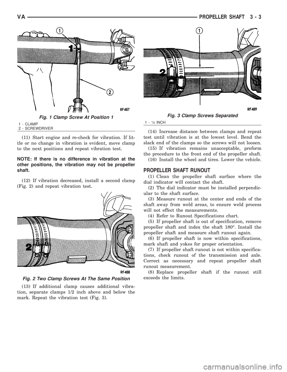
(11) Start engine and re-check for vibration. If lit-
tle or no change in vibration is evident, move clamp
to the next positions and repeat vibration test.
NOTE: If there is no difference in vibration at the
other positions, the vibration may not be propeller
shaft.
(12) If vibration decreased, install a second clamp
(Fig. 2) and repeat vibration test.
(13) If additional clamp causes additional vibra-
tion, separate clamps 1/2 inch above and below the
mark. Repeat the vibration test (Fig. 3).(14) Increase distance between clamps and repeat
test until vibration is at the lowest level. Bend the
slack end of the clamps so the screws will not loosen.
(15) If vibration remains unacceptable, preform
the procedure to the front end of the propeller shaft.
(16) Install the wheel and tires. Lower the vehicle.
PROPELLER SHAFT RUNOUT
(1) Clean the propeller shaft surface where the
dial indicator will contact the shaft.
(2) The dial indicator must be installed perpendic-
ular to the shaft surface.
(3) Measure runout at the center and ends of the
shaft away from weld areas, to ensure weld process
will not effect the measurements.
(4) Refer to Runout Specifications chart.
(5) If propeller shaft is out of specification, remove
propeller shaft and index the shaft 180É. Install the
propeller shaft and measure shaft runout again.
(6) If propeller shaft is now within specifications,
mark shaft and yokes for proper orientation.
(7) If propeller shaft runout is not within specifica-
tions, check runout of the transmission and axle.
Correct as necessary and repeat propeller shaft
runout measurement.
(8) Replace propeller shaft if the runout still
exceeds the limits.
Fig. 1 Clamp Screw At Position 1
1 - CLAMP
2 - SCREWDRIVER
Fig. 2 Two Clamp Screws At The Same Position
Fig. 3 Clamp Screws Separated
1-1¤2INCH
VAPROPELLER SHAFT 3 - 3
Page 758 of 2305
LOW SPEED KNOCK
Low speed knock is generally caused by a worn
U-joint or by worn side-gear thrust washers. A worn
pinion shaft bore will also cause low speed knock.
VIBRATION
Vibration at the rear of the vehicle is usually
caused by a:
²Damaged drive shaft.
²Missing drive shaft balance weight(s).
²Worn or out-of-balance wheels.
²Loose wheel lug nuts.
²Worn U-joint(s).
²Loose/broken springs.
²Damaged axle shaft bearing(s).
²Loose pinion gear nut.
²Excessive pinion yoke run out.
²Bent axle shaft(s).
Check for loose or damaged front-end components
or engine/transmission mounts. These components
can contribute to what appears to be a rearend vibra-
tion. Do not overlook engine accessories, brackets
and drive belts.
NOTE: All driveline components should be exam-
ined before starting any repair.
DRIVELINE SNAP
A snap or clunk noise when the vehicle is shifted
into gear (or the clutch engaged), can be caused by:
²High engine idle speed.
²Transmission shift operation.
²Loose engine/transmission/transfer case mounts.
²Worn U-joints.
²Loose spring mounts.
²Loose pinion gear nut and yoke.
²Excessive ring gear backlash.
²Excessive side gear to case clearance.
The source of a snap or a clunk noise can be deter-
mined with the assistance of a helper. Raise the vehi-
cle on a hoist with the wheels free to rotate. Instruct
the helper to shift the transmission into gear. Listen
for the noise, a mechanics stethoscope is helpful in
isolating the source of a noise.
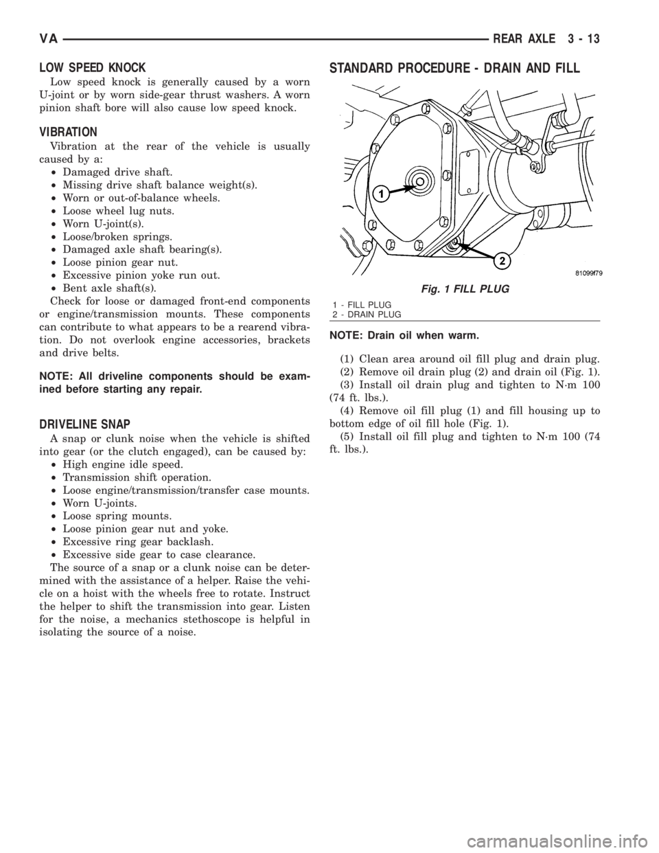
STANDARD PROCEDURE - DRAIN AND FILL
NOTE: Drain oil when warm.
(1) Clean area around oil fill plug and drain plug.
(2) Remove oil drain plug (2) and drain oil (Fig. 1).
(3) Install oil drain plug and tighten to N´m 100
(74 ft. lbs.).
(4) Remove oil fill plug (1) and fill housing up to
bottom edge of oil fill hole (Fig. 1).
(5) Install oil fill plug and tighten to N´m 100 (74
ft. lbs.).
Fig. 1 FILL PLUG
1 - FILL PLUG
2 - DRAIN PLUG
VAREAR AXLE 3 - 13