2006 MERCEDES-BENZ SPRINTER check engine
[x] Cancel search: check enginePage 791 of 2305
POWER BRAKE BOOSTER
DESCRIPTION.........................19
OPERATION...........................19
REMOVAL.............................20
INSTALLATION.........................20
ROTORS
REMOVAL
REMOVAL - FRONT (SRW)..............20
REMOVAL - REAR (SRW)...............20
REMOVAL - FRONT (DRW)..............21
REMOVAL - REAR (DRW)...............21
INSTALLATION
INSTALLATION - FRONT (SRW)..........22
INSTALLATION - REAR (SRW)...........22
INSTALLATION - FRONT (DRW)..........22
INSTALLATION - REAR (DRW)...........22
SUPPORT PLATE
REMOVAL - REAR......................23
INSTALLATION - REAR...................23
PARKING BRAKE
SPECIFICATIONS
TORQUE CHART......................23
SPECIAL TOOLS
PARK BRAKE........................24
CABLE TENSIONER
REMOVAL.............................24INSTALLATION.........................24
CABLES
REMOVAL
REMOVAL - FRONT....................24
REMOVAL - REAR.....................25
INSTALLATION
INSTALLATION - FRONT................25
INSTALLATION - REAR.................26
ADJUSTMENTS
ADJUSTMENT - PARKING BRAKE CABLES . 26
LEVER
REMOVAL.............................26
INSTALLATION.........................27
SHOES
REMOVAL
REMOVAL - (SRW)....................27
REMOVAL - (DRW)....................27
CLEANING - REAR DRUM IN HAT BRAKE....28
INSTALLATION
INSTALLATION - (SRW).................28
INSTALLATION - (DRW).................28
ADJUSTMENTS
ADJUSTMENT........................28
BRAKES - BASE
DIAGNOSIS AND TESTING - BASE BRAKE SYS-
TEM
Base brake components consist of the brake pads,
calipers, brake drum in hat rotor in the rear, rotors,
brake lines, master cylinder, booster, and parking
brake components.
Brake diagnosis involves determining if the prob-
lem is related to a mechanical, hydraulic, or vacuum
operated component.
The first diagnosis step is the preliminary check.
PRELIMINARY BRAKE CHECK
(1) Check condition of tires and wheels. Damaged
wheels and worn, damaged, or underinflated tires
can cause pull, shudder, vibration, and a condition
similar to grab.
(2) If complaint was based on noise when braking,
check suspension components. Jounce front and rear
of vehicle and listen for noise that might be caused
by loose, worn or damaged suspension or steering
components.
(3) Inspect brake fluid level and condition. Note
that the brake reservoir fluid level will decrease in
proportion to normal lining wear.Also note that
brake fluid tends to darken over time. This is
normal and should not be mistaken for contam-
ination.(a) If fluid level is abnormally low, look for evi-
dence of leaks at calipers, wheel cylinders, brake
lines, and master cylinder.
(b) If fluid appears contaminated, drain out a
sample to examine. System will have to be flushed
if fluid is separated into layers, or contains a sub-
stance other than brake fluid. The system seals
and cups will also have to be replaced after flush-
ing. Use clean brake fluid to flush the system.
(4) Check parking brake operation. Verify free
movement and full release of cables and pedal. Also
note if vehicle was being operated with parking
brake partially applied.
(5) Check brake pedal operation. Verify that pedal
does not bind and has adequate free play. If pedal
lacks free play, check pedal and power booster for
being loose or for bind condition. Do not road test
until condition is corrected.
(6) Check booster vacuum check valve and hose.
(7) If components checked appear OK, road test
the vehicle.
ROAD TESTING
(1) If complaint involved low brake pedal, pump
pedal and note if it comes back up to normal height.
(2) Check brake pedal response with transmission
in Neutral and engine running. Pedal should remain
firm under constant foot pressure.
5 - 2 BRAKES - BASEVA
Page 804 of 2305
FLUID
DIAGNOSIS AND TESTING - BRAKE FLUID
CONTAMINATION
Indications of fluid contamination are swollen or
deteriorated rubber parts.
Swollen rubber parts indicate the presence of
petroleum in the brake fluid.
To test for contamination, put a small amount of
drained brake fluid in clear glass jar. If fluid sepa-
rates into layers, there is mineral oil or other fluid
contamination of the brake fluid.
If brake fluid is contaminated, drain and thor-
oughly flush system. Replace master cylinder, ALB
Controller, caliper seals, Antilock Brakes hydraulic
unit and all hydraulic fluid hoses.
STANDARD PROCEDURE - BRAKE FLUID
LEVEL
Always clean the master cylinder reservoir and
caps before checking fluid level. If not cleaned, dirt
could enter the fluid.
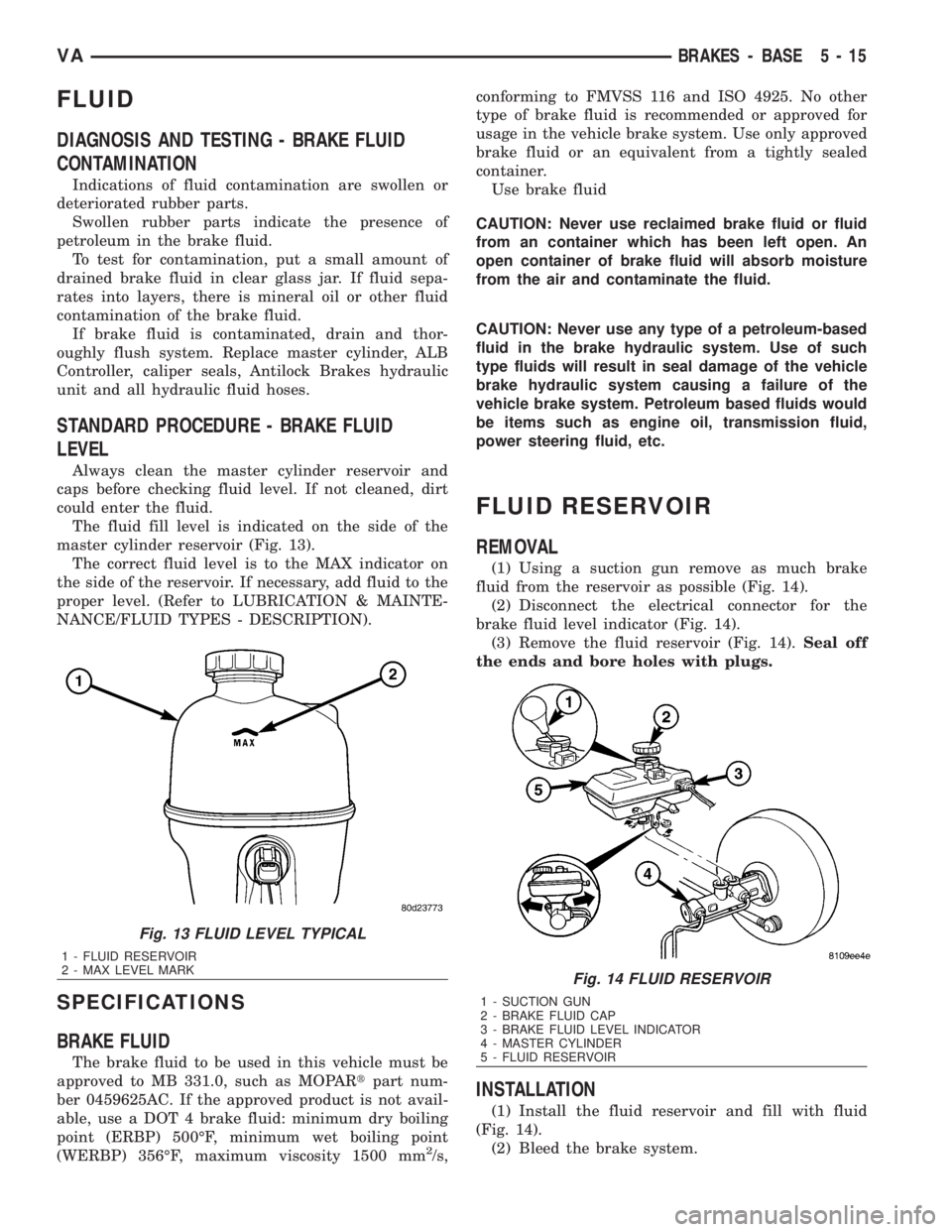
The fluid fill level is indicated on the side of the
master cylinder reservoir (Fig. 13).
The correct fluid level is to the MAX indicator on
the side of the reservoir. If necessary, add fluid to the
proper level. (Refer to LUBRICATION & MAINTE-
NANCE/FLUID TYPES - DESCRIPTION).
SPECIFICATIONS
BRAKE FLUID
The brake fluid to be used in this vehicle must be
approved to MB 331.0, such as MOPARtpart num-
ber 0459625AC. If the approved product is not avail-
able, use a DOT 4 brake fluid: minimum dry boiling
point (ERBP) 500ÉF, minimum wet boiling point
(WERBP) 356ÉF, maximum viscosity 1500 mm
2/s,conforming to FMVSS 116 and ISO 4925. No other
type of brake fluid is recommended or approved for
usage in the vehicle brake system. Use only approved
brake fluid or an equivalent from a tightly sealed
container.
Use brake fluid
CAUTION: Never use reclaimed brake fluid or fluid
from an container which has been left open. An
open container of brake fluid will absorb moisture
from the air and contaminate the fluid.
CAUTION: Never use any type of a petroleum-based
fluid in the brake hydraulic system. Use of such
type fluids will result in seal damage of the vehicle
brake hydraulic system causing a failure of the
vehicle brake system. Petroleum based fluids would
be items such as engine oil, transmission fluid,
power steering fluid, etc.
FLUID RESERVOIR
REMOVAL
(1) Using a suction gun remove as much brake
fluid from the reservoir as possible (Fig. 14).
(2) Disconnect the electrical connector for the
brake fluid level indicator (Fig. 14).
(3) Remove the fluid reservoir (Fig. 14).Seal off
the ends and bore holes with plugs.
INSTALLATION
(1) Install the fluid reservoir and fill with fluid
(Fig. 14).
(2) Bleed the brake system.
Fig. 13 FLUID LEVEL TYPICAL
1 - FLUID RESERVOIR
2 - MAX LEVEL MARK
Fig. 14 FLUID RESERVOIR
1 - SUCTION GUN
2 - BRAKE FLUID CAP
3 - BRAKE FLUID LEVEL INDICATOR
4 - MASTER CYLINDER
5 - FLUID RESERVOIR
VABRAKES - BASE 5 - 15
Page 806 of 2305
NOTE: The pressure gauge, connected at the ALB
controller must indicate the outlet pressure which
is assigned on the ALB plate to the rear axle load
determined.
NOTE: If the rear axle load determined is between
two figures indicated on the ALB plate, the outlet
pressure should be determined accordingly.
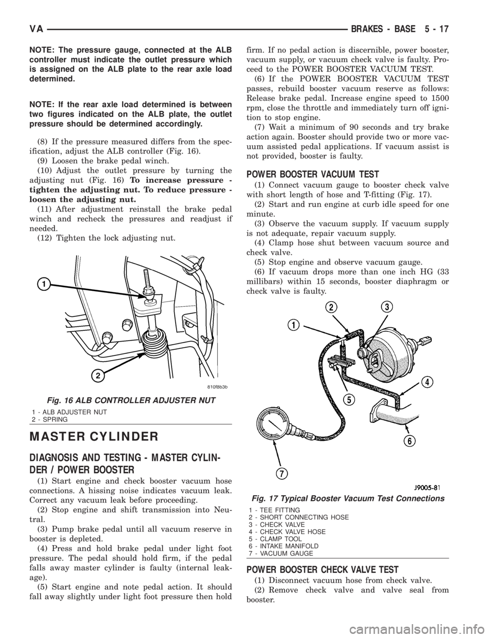
(8) If the pressure measured differs from the spec-
ification, adjust the ALB controller (Fig. 16).
(9) Loosen the brake pedal winch.
(10) Adjust the outlet pressure by turning the
adjusting nut (Fig. 16)To increase pressure -
tighten the adjusting nut. To reduce pressure -
loosen the adjusting nut.
(11) After adjustment reinstall the brake pedal
winch and recheck the pressures and readjust if
needed.
(12) Tighten the lock adjusting nut.
MASTER CYLINDER
DIAGNOSIS AND TESTING - MASTER CYLIN-
DER / POWER BOOSTER
(1) Start engine and check booster vacuum hose
connections. A hissing noise indicates vacuum leak.
Correct any vacuum leak before proceeding.
(2) Stop engine and shift transmission into Neu-
tral.
(3) Pump brake pedal until all vacuum reserve in
booster is depleted.
(4) Press and hold brake pedal under light foot
pressure. The pedal should hold firm, if the pedal
falls away master cylinder is faulty (internal leak-
age).
(5) Start engine and note pedal action. It should
fall away slightly under light foot pressure then holdfirm. If no pedal action is discernible, power booster,
vacuum supply, or vacuum check valve is faulty. Pro-
ceed to the POWER BOOSTER VACUUM TEST.
(6) If the POWER BOOSTER VACUUM TEST
passes, rebuild booster vacuum reserve as follows:
Release brake pedal. Increase engine speed to 1500
rpm, close the throttle and immediately turn off igni-
tion to stop engine.
(7) Wait a minimum of 90 seconds and try brake
action again. Booster should provide two or more vac-
uum assisted pedal applications. If vacuum assist is
not provided, booster is faulty.
POWER BOOSTER VACUUM TEST
(1) Connect vacuum gauge to booster check valve
with short length of hose and T-fitting (Fig. 17).
(2) Start and run engine at curb idle speed for one
minute.
(3) Observe the vacuum supply. If vacuum supply
is not adequate, repair vacuum supply.
(4) Clamp hose shut between vacuum source and
check valve.
(5) Stop engine and observe vacuum gauge.
(6) If vacuum drops more than one inch HG (33
millibars) within 15 seconds, booster diaphragm or
check valve is faulty.
POWER BOOSTER CHECK VALVE TEST
(1) Disconnect vacuum hose from check valve.
(2) Remove check valve and valve seal from
booster.
Fig. 16 ALB CONTROLLER ADJUSTER NUT
1 - ALB ADJUSTER NUT
2 - SPRING
Fig. 17 Typical Booster Vacuum Test Connections
1 - TEE FITTING
2 - SHORT CONNECTING HOSE
3 - CHECK VALVE
4 - CHECK VALVE HOSE
5 - CLAMP TOOL
6 - INTAKE MANIFOLD
7 - VACUUM GAUGE
VABRAKES - BASE 5 - 17
Page 809 of 2305
edge of the diaphragm is secured to the housing. The
booster push rod, which connects the booster to the
brake pedal and master cylinder, is attached to the
center of the diaphragm. A check valve is used in the
booster outlet connected to the engine intake mani-
fold. Power assist is generated by utilizing a combi-
nation of vacuum and atmospheric pressure to boost
brake assist.
REMOVAL
(1) Using a suction gun remove as much brake
fluid from the reservoir as possible.
(2) Disconnect the brake level switch electrical
connector.
(3) Remove the brake lines from the master cylin-
derSeal off the ends and bore holes with plugs.
(4) Remove the master cylinder from the booster.
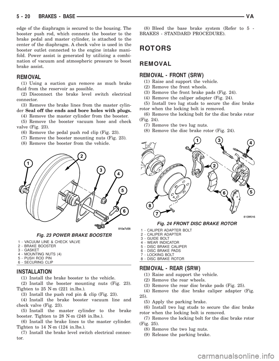
(5) Remove the booster vacuum hose and check
valve (Fig. 23).
(6) Remove the pedal push rod clip (Fig. 23).
(7) Remove the booster mounting nuts (Fig. 23).
(8) Remove the booster from the vehicle.
INSTALLATION
(1) Install the brake booster to the vehicle.
(2) Install the booster mounting nuts (Fig. 23).
Tighten to 25 N´m (221 in.lbs.).
(3) Install the push rod pin & clip (Fig. 23).
(4) Install the brake booster vacuum line and
check valve (Fig. 23).
(5) Install the master cylinder to the brake
booster. Tighten to 28 N´m (248 in.lbs.).
(6) Install the brake lines to the master cylinder.
Tighten to 14 N´m (124 in.lbs.).
(7) Install the brake level switch electrical connec-
tor.(8) Bleed the base brake system (Refer to 5 -
BRAKES - STANDARD PROCEDURE).
ROTORS
REMOVAL
REMOVAL - FRONT (SRW)
(1) Raise and support the vehicle.
(2) Remove the front wheels.
(3) Remove the front brake pads (Fig. 24).
(4) Remove the caliper adapter (Fig. 24).
(5) Install two lug studs to secure the disc brake
rotor when the locking bolt is removed.
(6) Remove the locking bolt for the disc brake rotor
(Fig. 24).
(7) Remove the two lug nuts.
(8) Remove the disc brake rotor (Fig. 24).
REMOVAL - REAR (SRW)
(1) Raise and support the vehicle.
(2) Remove the rear wheels.
(3) Remove the rear disc brake pads (Fig. 25).
(4) Remove the disc brake caliper adapter (Fig.
25).
(5) Apply the parking brake.
(6) Install two lug studs to secure the disc brake
rotor when the locking bolt is removed.
(7) Remove the locking bolt for the disc brake rotor
(Fig. 25).
(8) Remove the two lug nuts.
(9) Release the parking brake.
Fig. 23 POWER BRAKE BOOSTER
1 - VACUUM LINE & CHECK VALVE
2 - BRAKE BOOSTER
3 - GASKET
4 - MOUNTING NUTS (4)
5 - PUSH ROD PIN
6 - SECURING CLIP
Fig. 24 FRONT DISC BRAKE ROTOR
1 - CALIPER ADAPTER BOLT
2 - CALIPER ADAPTER
3 - GUIDE BOLT
4 - WEAR INDICATOR
5 - DISC BRAKE CALIPER
6 - DISC BRAKE PADS
7 - LOCKING BOLT
8 - DISC BRAKE ROTOR
5 - 20 BRAKES - BASEVA
Page 828 of 2305
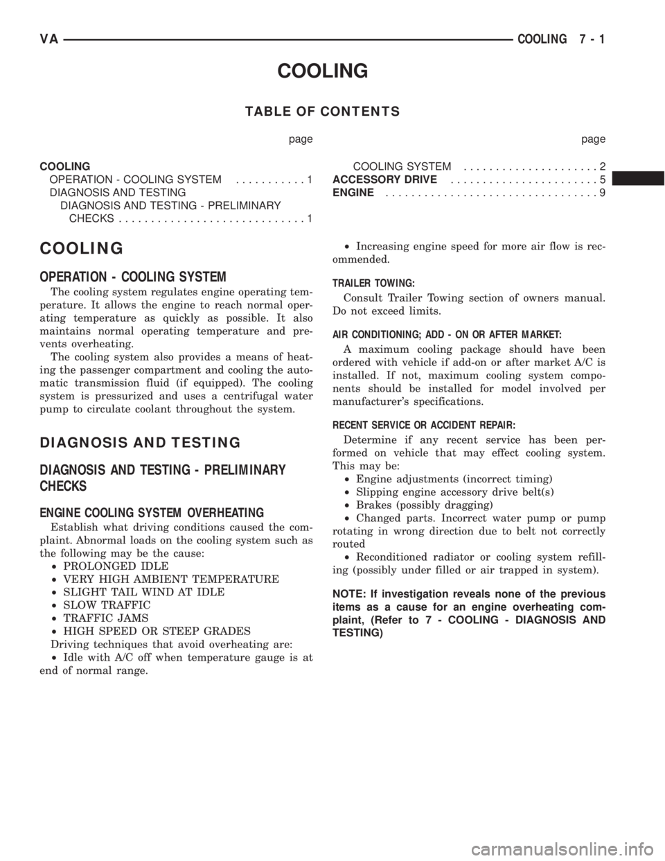
COOLING
TABLE OF CONTENTS
page page
COOLING
OPERATION - COOLING SYSTEM...........1
DIAGNOSIS AND TESTING
DIAGNOSIS AND TESTING - PRELIMINARY
CHECKS.............................1COOLING SYSTEM.....................2
ACCESSORY DRIVE.......................5
ENGINE.................................9
COOLING
OPERATION - COOLING SYSTEM
The cooling system regulates engine operating tem-
perature. It allows the engine to reach normal oper-
ating temperature as quickly as possible. It also
maintains normal operating temperature and pre-
vents overheating.
The cooling system also provides a means of heat-
ing the passenger compartment and cooling the auto-
matic transmission fluid (if equipped). The cooling
system is pressurized and uses a centrifugal water
pump to circulate coolant throughout the system.
DIAGNOSIS AND TESTING
DIAGNOSIS AND TESTING - PRELIMINARY
CHECKS
ENGINE COOLING SYSTEM OVERHEATING
Establish what driving conditions caused the com-
plaint. Abnormal loads on the cooling system such as
the following may be the cause:
²PROLONGED IDLE
²VERY HIGH AMBIENT TEMPERATURE
²SLIGHT TAIL WIND AT IDLE
²SLOW TRAFFIC
²TRAFFIC JAMS
²HIGH SPEED OR STEEP GRADES
Driving techniques that avoid overheating are:
²Idle with A/C off when temperature gauge is at
end of normal range.²Increasing engine speed for more air flow is rec-
ommended.
TRAILER TOWING:
Consult Trailer Towing section of owners manual.
Do not exceed limits.
AIR CONDITIONING; ADD - ON OR AFTER MARKET:
A maximum cooling package should have been
ordered with vehicle if add-on or after market A/C is
installed. If not, maximum cooling system compo-
nents should be installed for model involved per
manufacturer's specifications.
RECENT SERVICE OR ACCIDENT REPAIR:
Determine if any recent service has been per-
formed on vehicle that may effect cooling system.
This may be:
²Engine adjustments (incorrect timing)
²Slipping engine accessory drive belt(s)
²Brakes (possibly dragging)
²Changed parts. Incorrect water pump or pump
rotating in wrong direction due to belt not correctly
routed
²Reconditioned radiator or cooling system refill-
ing (possibly under filled or air trapped in system).
NOTE: If investigation reveals none of the previous
items as a cause for an engine overheating com-
plaint, (Refer to 7 - COOLING - DIAGNOSIS AND
TESTING)
VACOOLING 7 - 1
Page 829 of 2305
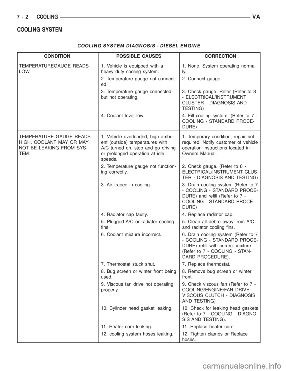
COOLING SYSTEM
COOLING SYSTEM DIAGNOSIS - DIESEL ENGINE
CONDITION POSSIBLE CAUSES CORRECTION
TEMPERATUREGAUGE READS
LOW1. Vehicle is equipped with a
heavy duty cooling system.1. None. System operating norma-
ly.
2. Temperature gauge not connect-
ed2. Connect gauge.
3. Temperature gauge connected
but not operating.3. Check gauge. Refer (Refer to 8
- ELECTRICAL/INSTRUMENT
CLUSTER - DIAGNOSIS AND
TESTING)
4. Coolant level low. 4. Fill cooling system. (Refer to 7 -
COOLING - STANDARD PROCE-
DURE)
TEMPERATURE GAUGE READS
HIGH. COOLANT MAY OR MAY
NOT BE LEAKING FROM SYS-
TEM1. Vehicle overloaded, high ambi-
ent (outside) temperatures with
A/C turned on, stop and go driving
or prolonged operation at idle
speeds.1. Temporary condition, repair not
required. Notify customer of vehicle
operation instructions located in
Owners Manual.
2. Temperature gauge not function-
ing correctly.2. Check gauge. (Refer to 8 -
ELECTRICAL/INSTRUMENT CLUS-
TER - DIAGNOSIS AND TESTING)
3. Air traped in cooling 3. Drain cooling system (Refer to 7
- COOLING - STANDARD PROCE-
DURE) and refill (Refer to 7 -
COOLING - STANDARD PROCE-
DURE)
4. Radiator cap faulty. 4. Replace radiator cap.
5. Plugged A/C or radiator cooling
fins.5. Clean all debre away from A/C
and radiator cooling fins.
6. Coolant mixture incorrect. 6. Drain cooling system (Refer to 7
- COOLING - STANDARD PROCE-
DURE) refill with correct mixture
(Refer to 7 - COOLING - STAN-
DARD PROCEDURE).
7. Thermostat stuck shut. 7. Replace thermostat.
8. Bug screen or winter front being
used.8. Remove bug screen or winter
front.
9. Viscous fan drive not operating
properly.9. Check viscous fan (Refer to 7 -
COOLING/ENGINE/FAN DRIVE
VISCOUS CLUTCH - DIAGNOSIS
AND TESTING)
10. Cylinder head gasket leaking. 10. Check for leaking head gaskets
(Refer to 7 - COOLING - DIAGNO-
SIS AND TESTING).
11. Heater core leaking. 11. Replace heater core.
12. cooling system hoses leaking. 12. Tighten clamps or Replace
hoses.
7 - 2 COOLINGVA
Page 830 of 2305

CONDITION POSSIBLE CAUSES CORRECTION
13. Brakes dragging. 13. Check brakes. (Refer to 5 -
BRAKES/HYDRAULIC/MECHANI-
CAL - DIAGNOSIS AND TESTING)
TEMPERATURE GAUGE READ-
ING INCONSISTENT ( ERRATIC,
CYCLES OR FLUCTUATES)1. Heavy duty cooling system, ex-
tream cold ambient (outside) tem-
perature or heater blower motor in
high position.1. None. System operating norma-
ly.
2. Temperature gauge or gauge
sensor defective.2. Check gauge. (Refer to 8 -
ELECTRICAL/INSTRUMENT CLUS-
TER - DIAGNOSIS AND TESTING)
3. Temporary heavy usage or load. 3. None. Normal condition.
4. Air traped in cooling system. 4. Fill cooling system (Refer to 7 -
COOLING - STANDARD PROCE-
DURE).
5. Water pump 5. Replace water pump.
6. Air leak on suction side of water
pump.6. Check for leak. (Refer to 7 -
COOLING - DIAGNOSIS AND
TESTING)
RADIATOR CAP LEAKING STEAM
AND /OR COOLANT INTO RES-
ERVOIR BOTTLE. (TEMPERA-
TURE GAUGE MAY READ HIGH)1. Radiator cap defective. 1. Replace radiator cap.
2. Radiator neck surface damaged. 2. Replace radiator.
HOSE OR HOSES COLLAPSE
WHEN ENGINE IS COOLING.1. Vacuum created in cooling sys-
tem on engine cool-down is not
being relieved through coolant re-
servior/overflow system.1. Replace radiator cap, check vent
hose between radiator and reser-
voir bottle for blockage also check
reservoir bottle vent for blockage.
NOISY FAN 1. Fan blade(s) loose, damaged. 1. Replace fan blade assembly.
2. Thermal viscous fan drive. 2. None. Normal condition.
3. Fan blades striking surrounding
objects.3. Locate contact point and repair
as necessary.
4. Thermal viscous fan drive bear-
ing.4. Replace viscous fan drive as-
sembly.
5. Obstructed air flow through radi-
ator.5. Remove obstruction.
INADEQUATE AIR CONDITIONER
PERFORMANCE (COOLING SYS-
TEM SUSPECTED)1. Radiator and/or A/C condenser
air flow obstructed.1. Remove obstruction and/or
clean.
2. Thermal viscous fan drive not
working.2. Check fan drive. (Refer to 7 -
COOLING/ENGINE/FAN DRIVE
VISCOUS CLUTCH - DIAGNOSIS
AND TESTING)
3. Air seals around radiator dam-
aged or missing.3. Inspect air seals, repair or re-
place as necessary.
VACOOLING 7 - 3
Page 831 of 2305
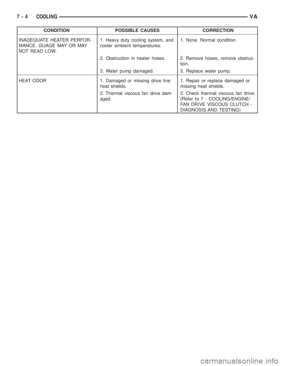
CONDITION POSSIBLE CAUSES CORRECTION
INADEQUATE HEATER PERFOR-
MANCE. GUAGE MAY OR MAY
NOT READ LOW.1. Heavy duty cooling system, and
cooler ambient temperatures.1. None. Normal condition.
2. Obstruction in heater hoses. 2. Remove hoses, remove obstruc-
tion.
3. Water pump damaged. 3. Replace water pump.
HEAT ODOR 1. Damaged or missing drive line
heat shields.1. Repair or replace damaged or
missing heat shields.
2. Thermal viscous fan drive dam-
aged.2. Check thermal viscous fan drive.
(Refer to 7 - COOLING/ENGINE/
FAN DRIVE VISCOUS CLUTCH -
DIAGNOSIS AND TESTING)
7 - 4 COOLINGVA