2006 MERCEDES-BENZ SPRINTER automatic transmission
[x] Cancel search: automatic transmissionPage 669 of 2305

Verification Tests
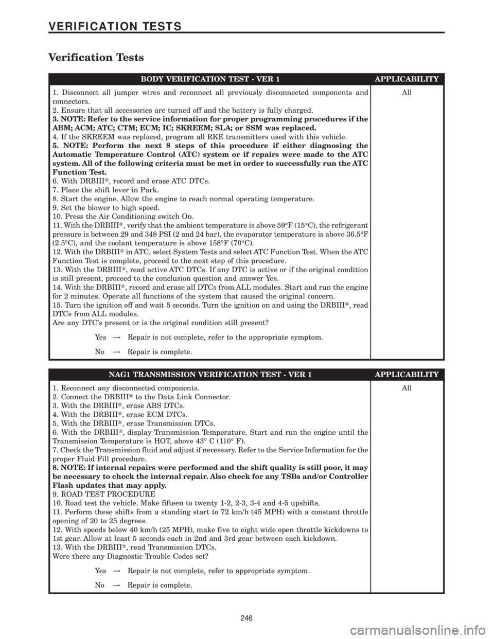
BODY VERIFICATION TEST - VER 1 APPLICABILITY
1. Disconnect all jumper wires and reconnect all previously disconnected components and
connectors.
2. Ensure that all accessories are turned off and the battery is fully charged.
3. NOTE: Refer to the service information for proper programming procedures if the
ABM; ACM; ATC; CTM; ECM; IC; SKREEM; SLA; or SSM was replaced.
4. If the SKREEM was replaced, program all RKE transmitters used with this vehicle.
5. NOTE: Perform the next 8 steps of this procedure if either diagnosing the
Automatic Temperature Control (ATC) system or if repairs were made to the ATC
system. All of the following criteria must be met in order to successfully run the ATC
Function Test.
6. With DRBIIIt, record and erase ATC DTCs.
7. Place the shift lever in Park.
8. Start the engine. Allow the engine to reach normal operating temperature.
9. Set the blower to high speed.
10. Press the Air Conditioning switch On.
11. With the DRBIIIt, verify that the ambient temperature is above 59ÉF (15ÉC), the refrigerant
pressure is between 29 and 348 PSI (2 and 24 bar), the evaporator temperature is above 36.5ÉF
(2.5ÉC), and the coolant temperature is above 158ÉF (70ÉC).
12. With the DRBIIItin ATC, select System Tests and select ATC Function Test. When the ATC
Function Test is complete, proceed to the next step of this procedure.
13. With the DRBIIIt, read active ATC DTCs. If any DTC is active or if the original condition
is still present, proceed to the conclusion question and answer Yes.
14. With the DRBIIIt, record and erase all DTCs from ALL modules. Start and run the engine
for 2 minutes. Operate all functions of the system that caused the original concern.
15. Turn the ignition off and wait 5 seconds. Turn the ignition on and using the DRBIIIt, read
DTCs from ALL modules.
Are any DTC's present or is the original condition still present?All
Ye s!Repair is not complete, refer to the appropriate symptom.
No!Repair is complete.
NAG1 TRANSMISSION VERIFICATION TEST - VER 1 APPLICABILITY
1. Reconnect any disconnected components.
2. Connect the DRBIIItto the Data Link Connector.
3. With the DRBIIIt, erase ABS DTCs.
4. With the DRBIIIt, erase ECM DTCs.
5. With the DRBIIIt, erase Transmission DTCs.
6. With the DRBIIIt, display Transmission Temperature. Start and run the engine until the
Transmission Temperature is HOT, above 43É C (110É F).
7. Check the Transmission fluid and adjust if necessary. Refer to the Service Information for the
proper Fluid Fill procedure.
8. NOTE: If internal repairs were performed and the shift quality is still poor, it may
be necessary to check the internal repair. Also check for any TSBs and/or Controller
Flash updates that may apply.
9. ROAD TEST PROCEDURE
10. Road test the vehicle. Make fifteen to twenty 1-2, 2-3, 3-4 and 4-5 upshifts.
11. Perform these shifts from a standing start to 72 km/h (45 MPH) with a constant throttle
opening of 20 to 25 degrees.
12. With speeds below 40 km/h (25 MPH), make five to eight wide open throttle kickdowns to
1st gear. Allow at least 5 seconds each in 2nd and 3rd gear between each kickdown.
13. With the DRBIIIt, read Transmission DTCs.
Were there any Diagnostic Trouble Codes set?All
Ye s!Repair is not complete, refer to appropriate symptom.
No!Repair is complete.
246
VERIFICATION TESTS
Page 716 of 2305

LUBRICATION & MAINTENANCE
TABLE OF CONTENTS
page page
FLUID TYPES
DESCRIPTION
PARTS AND LUBRICANT
RECOMMENDATIONS...................1
AUTOMATIC TRANSMISSION FLUID - NAG1 . 1
AXLE FLUID..........................2
BRAKE FLUID.........................2
HOAT COOLANT.......................2
ENGINE OIL - DIESEL ENGINES...........3
FUEL REQUIREMENTS - DIESEL ENGINE . . . 4
POWER STEERING FLUID...............5
OPERATION - AUTOMATIC TRANSMISSION
FLUID...............................5
FLUID CAPACITIES
SPECIFICATIONS - FLUID CAPACITIES.......5FLUID FILL/CHECK LOCATIONS
INSPECTION - FLUID FILL/CHECK
LOCATIONS..........................5
HOISTING
STANDARD PROCEDURE - HOISTING........5
JUMP STARTING
STANDARD PROCEDURE - JUMP STARTING . . 6
TOWING
STANDARD PROCEDURE - TOWING.........7
MAINTENANCE SCHEDULES
DESCRIPTION..........................8
INTERNATIONAL SYMBOLS
DESCRIPTION..........................9
FLUID TYPES
DESCRIPTION
PARTS AND LUBRICANT RECOMMENDATIONS
Lubricating grease is rated for quality and usage
by the NLGI. All approved products have the NLGI
symbol (Fig. 1) on the label. At the bottom NLGI
symbol is the usage and quality identification letters.
Wheel bearing lubricant is identified by the letter
ªGº. Chassis lubricant is identified by the latter ªLº.
The letter following the usage letter indicates the
quality of the lubricant. The following symbols indi-
cate the highest quality.
When service is required, DaimlerChrysler Corpo-
ration recommends that only MOPARtbrand parts,
lubricants and chemicals be used. MOPARtprovides
the best engineered products for servicing
DaimlerChrysler Corporation vehicles.
AUTOMATIC TRANSMISSION FLUID - NAG1
NOTE: Refer to Service Procedures in this group for
fluid level checking procedures.
Use ATF approved to MB 236.10, MB 236.12, such
as Shell ATF 3403/M-115, MOPARtpart number
05127382AA, Fuchs/Shell ATF 3353, or equivalent.
Automatic Transmission Fluid (ATF) is red in color
when new. The ATF is dyed red so it can be identified
from other fluids used in the vehicle such as engine
oil or antifreeze. The red color is not permanent and
is not an indicator of fluid condition. As the vehicle is
driven, the ATF will begin to look darker in color and
may eventually become brown.This is normal.
FLUID ADDITIVES
DaimlerChrysler strongly recommends against the
addition of any fluids to the transmission, other than
those automatic transmission fluids listed above.
Exceptions to this policy are the use of special dyes
to aid in detecting fluid leaks.
Various ªspecialº additives and supplements exist
that claim to improve shift feel and/or quality. These
additives and others also claim to improve converter
clutch operation and inhibit overheating, oxidation,
varnish, and sludge. These claims have not been sup-
ported to the satisfaction of DaimlerChrysler and
these additivesmust not be used.The use of trans-
mission ªsealersº should also be avoided, since they
may adversely affect the integrity of transmission
seals.
Fig. 1 NLGI Symbol
1 - WHEEL BEARINGS
2 - CHASSIS LUBRICATION
3 - CHASSIS AND WHEEL BEARINGS
VALUBRICATION & MAINTENANCE 0 - 1
Page 720 of 2305

Do not blend other specific fuel additives with die-
sel fuel. They only result in unnecessary cost, and
may be harmful to the engine operation.
POWER STEERING FLUID
No fluid service required. Filled with Power Steer-
ing Fluid approved to MB 236.3, such as Mobil
ATF-D (Exxon Mobil Corporation) or equivalent.
OPERATION - AUTOMATIC TRANSMISSION
FLUID
The automatic transmission fluid is selected based
upon several qualities. The fluid must provide a high
level of protection for the internal components by
providing a lubricating film between adjacent metal
components. The fluid must also be thermally stable
so that it can maintain a consistent viscosity through
a large temperature range. If the viscosity stays con-
stant through the temperature range of operation,
transmission operation and shift feel will remain con-
sistent. Transmission fluid must also be a good con-
ductor of heat. The fluid must absorb heat from the
internal transmission components and transfer that
heat to the transmission case.
FLUID CAPACITIES
SPECIFICATIONS - FLUID CAPACITIES
DESCRIPTION SPECIFICATION
ENGINE COOLANT
10 Liters 10.5 Quarts
ENGINE OIL
9.0L without Filter Re-
placement9.5 Quarts with Filter
Replacement
AUTOMATIC TRANSMISSION
Service Fill - NAG1 5.0 L (10.6 pts.)
O-haul Fill - NAG1 7.7 L (16.3 pts.)
Dry fill capacity Depending on type and size of inter-
nal cooler, length and inside diameter of cooler lines,
or use of an auxiliary cooler, these figures may vary.
(Refer to appropriate 21 - TRANSMISSION/AUTO-
MATIC/FLUID - STANDARD PROCEDURE).
REAR AXLE .03L (1 oz.)
8 1/2 1.8 L (4.0 pts.)
FUEL TANK
Primary 100 L (26.4 gal.)*
Reserve 10.5 L (2.8 gal.)*
*Nominal refill capacities are shown. A variation may
be observed from vehicle to vehicle due to manufac-
turing tolerance and refill procedure
DESCRIPTION SPECIFICATION
POWER STEERING SYSTEM
Power steering fluid capacities are dependent on
engine/chassis options as well as steering gear/cool-
er options. Depending on type and size of internal
cooler, length and inside diameter of cooler lines, or
use of an auxiliary cooler, these capacities may vary.
Refer to 19, Steering for proper fill and bleed proce-
dures.
FLUID FILL / CHECK LOCA-
TIONS
INSPECTION - FLUID FILL / CHECK LOCA-
TIONS
The fluid fill/check locations and lubrication points
are located in each applicable group.
HOISTING
STANDARD PROCEDURE - HOISTING
Refer to the Owner's Manual for emergency vehicle
lifting procedures.
WARNING: THE HOISTING AND JACK LIFTING
POINTS PROVIDED ARE FOR A COMPLETE VEHI-
CLE. WHEN A CHASSIS OR DRIVETRAIN COMPO-
NENT IS REMOVED FROM A VEHICLE, THE
CENTER OF GRAVITY IS ALTERED MAKING SOME
HOISTING CONDITIONS UNSTABLE. PROPERLY
SUPPORT OR SECURE VEHICLE TO HOISTING
DEVICE WHEN THESE CONDITIONS EXIST.
FLOOR JACK
When properly positioned, a floor jack can be used
to lift a vehicle. Support the vehicle in the raised
position with jack stands at the front and rear ends
of the frame rails.
CAUTION: Do not lift vehicle with a floor jack posi-
tioned under:
²An axle tube.
²A body side sill.
²A steering linkage component.
²A drive shaft.
²The engine or transmission oil pan.
²The fuel tank.
²A front suspension arm.
VALUBRICATION & MAINTENANCE 0 - 5
Page 721 of 2305

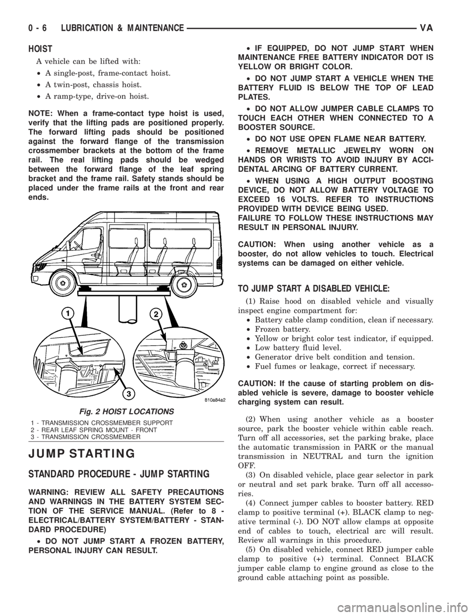
HOIST
A vehicle can be lifted with:
²A single-post, frame-contact hoist.
²A twin-post, chassis hoist.
²A ramp-type, drive-on hoist.
NOTE: When a frame-contact type hoist is used,
verify that the lifting pads are positioned properly.
The forward lifting pads should be positioned
against the forward flange of the transmission
crossmember brackets at the bottom of the frame
rail. The real lifting pads should be wedged
between the forward flange of the leaf spring
bracket and the frame rail. Safety stands should be
placed under the frame rails at the front and rear
ends.
JUMP STARTING
STANDARD PROCEDURE - JUMP STARTING
WARNING: REVIEW ALL SAFETY PRECAUTIONS
AND WARNINGS IN THE BATTERY SYSTEM SEC-
TION OF THE SERVICE MANUAL. (Refer to 8 -
ELECTRICAL/BATTERY SYSTEM/BATTERY - STAN-
DARD PROCEDURE)
²DO NOT JUMP START A FROZEN BATTERY,
PERSONAL INJURY CAN RESULT.²IF EQUIPPED, DO NOT JUMP START WHEN
MAINTENANCE FREE BATTERY INDICATOR DOT IS
YELLOW OR BRIGHT COLOR.
²DO NOT JUMP START A VEHICLE WHEN THE
BATTERY FLUID IS BELOW THE TOP OF LEAD
PLATES.
²DO NOT ALLOW JUMPER CABLE CLAMPS TO
TOUCH EACH OTHER WHEN CONNECTED TO A
BOOSTER SOURCE.
²DO NOT USE OPEN FLAME NEAR BATTERY.
²REMOVE METALLIC JEWELRY WORN ON
HANDS OR WRISTS TO AVOID INJURY BY ACCI-
DENTAL ARCING OF BATTERY CURRENT.
²WHEN USING A HIGH OUTPUT BOOSTING
DEVICE, DO NOT ALLOW BATTERY VOLTAGE TO
EXCEED 16 VOLTS. REFER TO INSTRUCTIONS
PROVIDED WITH DEVICE BEING USED.
FAILURE TO FOLLOW THESE INSTRUCTIONS MAY
RESULT IN PERSONAL INJURY.
CAUTION: When using another vehicle as a
booster, do not allow vehicles to touch. Electrical
systems can be damaged on either vehicle.
TO JUMP START A DISABLED VEHICLE:
(1) Raise hood on disabled vehicle and visually
inspect engine compartment for:
²Battery cable clamp condition, clean if necessary.
²Frozen battery.
²Yellow or bright color test indicator, if equipped.
²Low battery fluid level.
²Generator drive belt condition and tension.
²Fuel fumes or leakage, correct if necessary.
CAUTION: If the cause of starting problem on dis-
abled vehicle is severe, damage to booster vehicle
charging system can result.
(2) When using another vehicle as a booster
source, park the booster vehicle within cable reach.
Turn off all accessories, set the parking brake, place
the automatic transmission in PARK or the manual
transmission in NEUTRAL and turn the ignition
OFF.
(3) On disabled vehicle, place gear selector in park
or neutral and set park brake. Turn off all accesso-
ries.
(4) Connect jumper cables to booster battery. RED
clamp to positive terminal (+). BLACK clamp to neg-
ative terminal (-). DO NOT allow clamps at opposite
end of cables to touch, electrical arc will result.
Review all warnings in this procedure.
(5) On disabled vehicle, connect RED jumper cable
clamp to positive (+) terminal. Connect BLACK
jumper cable clamp to engine ground as close to the
ground cable attaching point as possible.
Fig. 2 HOIST LOCATIONS
1 - TRANSMISSION CROSSMEMBER SUPPORT
2 - REAR LEAF SPRING MOUNT - FRONT
3 - TRANSMISSION CROSSMEMBER
0 - 6 LUBRICATION & MAINTENANCEVA
Page 724 of 2305

SCOPE OF WORK FOR MAINTENANCE SERVICE
Oil Service
²Engine: Oil change and filter replacement
Check fluid levels of the following system, refill as neces-
sary.
²If fluid is lost, trace and eliminate cause - as a
separate order.
²Power-assisted steering
Lubrication work:
²Trailer tow hitch (original equipment)
Maintenance
²ASSYST maintenance computer reset
Function check
²Signalling system, warning and indicator lamps
²Headlamps, exterior lighting
²Windshield wipers, windshield washer system
Check for leaks and damage
²Check for abrasion points and ensure that lines
are correctly routed!
²All lines and hoses, sensor cables
²Rubber boots on front axle drive shafts, rubber
boots on front axle suspension ball joints, shock
absorbers
²Check fluid levels for the following systems, cor-
rect as necessary
NOTE: Should there be a loss of fluid which cannot
be explained by regular use, trace and eliminate the
cause.
²Engine cooling system. Check corrosion inhibi-
tor/antifreeze, refill as necessary.
²Hydraulic brake system
²Battery
²Windshield washer system
Engine
²Fuel filter renewal - Every oil service
²Air cleaner with maintenance indicator:
²Check degree of contamination.
²Air cleaner filter element renewed as necessary.
Chassis and body
²Trailer coupling: Check operation, play and
retaining fixtures
²Secondary rubber springs: Visual check
²Tire pressures: Correct as necessary, including
spare tire
²Check thickness of brake pads
²Brake test
²Check condition of steering mechanism
²Heating/ventilation dust filter renewal
ADDITIONAL MAINTENANCE WORK
Automatic transmission once only at 80,000 miles / 128000
km
²Oil and filter change
During every second maintenance service
²Air cleaner without maintenance indicator:
²Air cleaner filter element renewal
²Check poly-V-belt for wear and signs of damage
During every fourth maintenance service
²Change rear axle fluid
ADDITIONAL MAINTENANCE WORK AFTER YEARS
Every 2 years
²Change brake fluid.
Every 3 years
²Air cleaner filter element renewal (note installa-
tion date)
Every 15 years or 100,000 miles
²Coolant renewal
²Note coolant composition
INTERNATIONAL SYMBOLS
DESCRIPTION
DaimlerChrysler Corporation uses international
symbols to identify engine compartment lubricant
and fluid inspection and fill locations (Fig. 3).
Fig. 3 INTERNATIONAL SYMBOLS
VALUBRICATION & MAINTENANCE 0 - 9
Page 856 of 2305

ELECTRONIC CONTROL MODULES
TABLE OF CONTENTS
page page
CENTRAL TIMER MODULE
DESCRIPTION..........................1
OPERATION............................1
DIAGNOSIS AND TESTING - CENTRAL TIMER
MODULE.............................2
REMOVAL.............................2
INSTALLATION..........................3
CONTROLLER ANTILOCK BRAKE
DESCRIPTION..........................3
REMOVAL.............................3INSTALLATION..........................3
ENGINE CONTROL MODULE
DESCRIPTION..........................3
REMOVAL.............................6
INSTALLATION..........................6
TRANSMISSION CONTROL MODULE
DESCRIPTION..........................6
OPERATION............................7
STANDARD PROCEDURE - TCM ADAPTATION . 10
CENTRAL TIMER MODULE
DESCRIPTION
The central timer module (CTM) is located beneath
the driver seat. The CTM uses information carried on
the programmable communications interface (PCI)
data bus network along with many hard wired inputs
to monitor many sensor and switch inputs. In
response to those inputs, the circuitry and program-
ming of the CTM allow it to supply the vehicle occu-
pants with audible and visual information, and to
control and integrate many functions and features of
the vehicle through both hard wired outputs and the
transmission of message outputs to other modules in
the vehicle over the PCI data bus.
The features that the CTM supports or controls
include the following:
²Central Locking- The CTM on vehicles
equipped with the optional Vehicle Theft Security
System (VTSS) includes a central locking/unlocking
feature.
²Enhanced Accident Response- The CTM pro-
vides an optional enhanced accident response fea-
ture. This is a programmable feature.
²Panic Mode- The CTM provides support for
the optional RKE system panic mode including horn,
headlamp, and park lamp flash features.
²Power Lock Control- The CTM provides the
optional power lock system features, including sup-
port for the automatic door lock and door lock inhibit
modes.
²Programmable Features- The CTM provides
support for certain programmable features.
²Remote Keyless Entry- The CTM provides
the optional Remote Keyless Entry (RKE) system fea-
tures, including support for the RKE Lock (with
optional horn and park lamps flash), Unlock (with
park lamps flash, driver-door-only unlock, andunlock-all-doors), Panic, and illuminated entry
modes, as well as the ability to be programmed to
recognize up to four RKE transmitters. The RKE
horn, driver-door-only unlock, and unlock-all-doors
features are programmable.
²Vehicle Theft Security System- The CTM
provides control of the optional Vehicle Theft Secu-
rity System (VTSS) features, including support for
the central locking/unlocking mode and control of the
Security indicator in the instrument cluster.
Hard wired circuitry connects the CTM to the elec-
trical system of the vehicle. Refer to the appropriate
wiring information.
Many of the features in the vehicle controlled or
supported by the CTM are programmable using the
DRBIIItscan tool. However, if any of the CTM hard-
ware components are damaged or faulty, the entire
CTM unit must be replaced. The hard wired inputs
or outputs of all CTM versions can be diagnosed
using conventional diagnostic tools and methods;
however, for diagnosis of the CTM or the PCI data
bus, the use of a DRBIIItscan tool is required. Refer
to the appropriate diagnostic information.
OPERATION
The central timer module (CTM) monitors many
hard wired switch and sensor inputs as well as those
resources it shares with other modules in the vehicle
through its communication over the programmable
communications interface (PCI) data bus network.
The internal programming and all of these inputs
allow the CTM to determine the tasks it needs to
perform and their priorities, as well as both the stan-
dard and optional features that it should provide.
The CTM then performs those tasks and provides
those features through both PCI data bus communi-
cation with other modules and hard wired outputs
through a number of driver circuits, relays, and
VAELECTRONIC CONTROL MODULES 8E - 1
Page 861 of 2305

rate and boost pressure are adjusted to the actual
injection quantity.
²Injection valve quantity drift compensation in
full load range: this function is to limit the maximum
injection quantity for engine protection. The injection
quantity signal is compared to the injection quantity
calculated from the oxygen sensor signal and MAF
signal. If the comparison shows that the actual injec-
tion quantity is too high, it is limited to the maxi-
mum permissible injection quantity
²Air-fuel ratio controlled smoke limiter (full load):
the smoke limiter limits the injection quantity on the
basis of the air-fuel ratio permissible at the smoke
limit depending on the measure mass air flow and
the calculated EGR rate. As a consequence, the gen-
eration of smoke due to an excess injection quantity
is avoided under all operating conditions. At the
same time, the oxygen sensor signal is used to
ensure that the air-fuel ratio is adjusted accordingly
A function referred to as air flow sensor drift com-
pensation detects and corrects the possible drifting of
the MAF sensor by comparing the air mass measured
by the MAF with the projected air mass as it is cal-
culated by the ECM in consideration of various influ-
encing conditions. It is the air flow drift
compensation that gives the MAF air mass measure-
ment the precision needed to use it for the function
mentioned above. The high precision of the MAF
measurement enables the calculation of the actual
injection quantity from the measured air mass and
from the oxygen sensor signal in order to correct
injection quantity. The MAF signal can also be used
as a input parameter for the smoke limiter.
REMOVAL
(1) Disconnect the negative battery cable.
(2) Disconnect the ECM harness connectors (Fig.
4).
(3) Grasp ECM and pull down firmly to release
ECM from the retaining bracket tensioning springs
(Fig. 4).
INSTALLATION
NOTE: THE ECM MUST BE PROGRAMMED TO SUP-
PORT THE VEHICLE OPTIONS PACKAGE.
(1) Position the ECM into the guide of the retain-
ing bracket (Fig. 4).
(2) Carefully push the ECM in to the bracket until
the bracket tensioning springs engage (Fig. 4).
(3) Connect the ECM wiring harness connectors
(Fig. 4).
(4) Connect negative battery cable.
TRANSMISSION CONTROL
MODULE
DESCRIPTION
The transmission control module (TCM) receives,
processes and sends various digital and analog sig-
nals related to the automatic transmission. In addi-
tion, it processes information received from other
vehicle systems, such as engine torque and speed,
accelerator pedal position, wheel speed, kick-down
switch, traction control information, etc.
The TCM is located under the driver's seat and is
connected to other control modules via a CAN bus. It
controls all shift functions to achieve smooth shift
comfort in all driving situations considering:
²Vehicle speed.
²Transmission status.
Fig. 4 ECM
1 - BRACKET
2 - ECM
3 - BRACKET TENSIONING SPRINGS
8E - 6 ELECTRONIC CONTROL MODULESVA
Page 863 of 2305

N2 and N3 Speed Sensors
The N2 and N3 Input Speed Sensors are two Hall-
effect speed sensors that are mounted internally in
the transmission and are used by the TCM to calcu-
late the transmission's input speed. Since the input
speed cannot be measured directly, two of the drive
elements are measured. Two input speed sensors
were required because both drive elements are not
active in all gears.
CAN C Bus Indirect Input Signals
A 2.5-volt bias (operating voltage) is present on the
CAN C bus any time the ignition switch is in the
RUN position. Both the TCM and the ABS apply this
bias. On this vehicle, the CAN C bus is used for mod-
ule data exchange only. The indirect inputs used on
the NAG1 electronic control system are:
²Wheel Speed Sensors.
²Brake Switch.
²Engine RPM.
²Engine Temperature.
²Cruise Control Status.
²Gear Limit Request.
²Throttle Position - 0% at idle, 100% at WOT. If
open, TCM assumes idle (0% throttle opening).
²Odometer Mileage
²Maximum Effective Torque.
²Engine in Limp-In Mode/Mileage Where DTC
Was Set.
BRAKE TRANSMISSION SHIFT INTERLOCK (BTSI)
The BTSI solenoid prevents shifting out of the
PARK position until the ignition key is in the RUN
position and the brake pedal is pressed. The TCM
controls the ground while the ignition switch supplies
power to the BTSI solenoid. The PCM monitors the
brake switch and broadcasts brake switch status
messages over the CAN C bus. If the park brake is
depressed and there is power (Run/Start) to SLA, the
BTSI solenoid deactivates.
SHIFT SCHEDULES
The basic shift schedule includes up and down-
shifts for all five gears. The TCM adapts the shift
program according to driving style, accelerator pedal
position and deviation of vehicle speed. Influencing
factors are:
²Road Conditions.
²Incline, Decline and Altitude.
²Trailer Operation, Loading.
²Engine Coolant Temperature.
²Cruise Control Operation.
²Sporty Driving Style.
²Low and High ATF Temperature.
Upshift
To :1-2 2-3 3-4 4-5
Activat-
ed By
Sole-
noid:1-2/4-5 2-3 3-4 1-2/4-5
Shift
Point
(at
35.2%
of throt-
tle)17.8
km/h
(11.6
mph)32.1
km/h
(19.95
mph)67.5
km/h
(41.94
mph)73.8
km/h
(45.86
mph)
Down-
shift
From:5-4 4-3 3-2 2-1
Activat-
ed By
Sole-
noid:1-2/4-5 3-4 2-3 1-2/4-5
Shift
Point55.7
km/h
(34.61
mph)40.5
km/h
(25.17
mph)24.4
km/h
(15.16
mph)15.1
km/h
(9.38
mph)
DOWNSHIFT SAFETY
Selector lever downshifts are not performed if inad-
missible high engine rpm is sensed.
ADAPTATION
To equalize tolerances and wear, an automatic
adaptation takes place for:
²Shift Time.
²Clutch Filling Time.
²Clutch Filling Pressure.
²Torque Converter Lock-Up Control.
Adaptation data may be stored permanently and to
some extent, can be diagnosed.
Driving Style Adaptation
The shift point is modified in steps based on the
information from the inputs. The control module
looks at inputs such as:
²vehicle acceleration and deceleration (calculated
by the TCM).
²rate of change as well as the position of the
throttle pedal (fuel injection information from the
ECM).
²lateral acceleration (calculated by the TCM).
²gear change frequency (how often the shift
occurs).
Based on how aggressive the driver is, the TCM
moves up the shift so that the present gear is held a
8E - 8 ELECTRONIC CONTROL MODULESVA