2006 MERCEDES-BENZ SPRINTER automatic transmission
[x] Cancel search: automatic transmissionPage 880 of 2305
The following operation will require a voltmeter
accurate to 1/10 (0.10) volt. Before performing this
test, be certain that the following procedures are
accomplished:
²The battery is fully-charged and tested. (Refer to
8 - ELECTRICAL/BATTERY SYSTEM/BATTERY -
STANDARD PROCEDURE).
²Fully engage the parking brake.
²Place the automatic transmission gearshift selec-
tor lever in the Park position.
²Verify that all lamps and accessories are turned
off.
²Prevent the engine from starting.
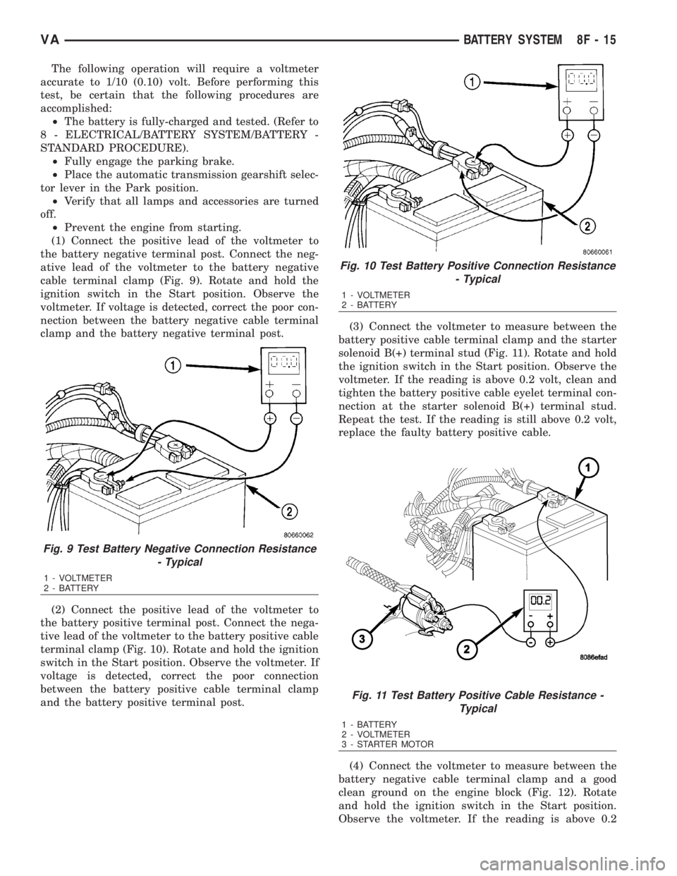
(1) Connect the positive lead of the voltmeter to
the battery negative terminal post. Connect the neg-
ative lead of the voltmeter to the battery negative
cable terminal clamp (Fig. 9). Rotate and hold the
ignition switch in the Start position. Observe the
voltmeter. If voltage is detected, correct the poor con-
nection between the battery negative cable terminal
clamp and the battery negative terminal post.
(2) Connect the positive lead of the voltmeter to
the battery positive terminal post. Connect the nega-
tive lead of the voltmeter to the battery positive cable
terminal clamp (Fig. 10). Rotate and hold the ignition
switch in the Start position. Observe the voltmeter. If
voltage is detected, correct the poor connection
between the battery positive cable terminal clamp
and the battery positive terminal post.(3) Connect the voltmeter to measure between the
battery positive cable terminal clamp and the starter
solenoid B(+) terminal stud (Fig. 11). Rotate and hold
the ignition switch in the Start position. Observe the
voltmeter. If the reading is above 0.2 volt, clean and
tighten the battery positive cable eyelet terminal con-
nection at the starter solenoid B(+) terminal stud.
Repeat the test. If the reading is still above 0.2 volt,
replace the faulty battery positive cable.
(4) Connect the voltmeter to measure between the
battery negative cable terminal clamp and a good
clean ground on the engine block (Fig. 12). Rotate
and hold the ignition switch in the Start position.
Observe the voltmeter. If the reading is above 0.2
Fig. 9 Test Battery Negative Connection Resistance
- Typical
1 - VOLTMETER
2 - BATTERY
Fig. 10 Test Battery Positive Connection Resistance
- Typical
1 - VOLTMETER
2 - BATTERY
Fig. 11 Test Battery Positive Cable Resistance -
Typical
1 - BATTERY
2 - VOLTMETER
3 - STARTER MOTOR
VABATTERY SYSTEM 8F - 15
Page 893 of 2305

STARTING SYSTEM
TABLE OF CONTENTS
page page
STARTING SYSTEM
DESCRIPTION.........................28
OPERATION...........................28
DIAGNOSIS AND TESTING - STARTING
SYSTEM............................29
SPECIFICATIONS
TORQUE - STARTER - DIESEL...........33
SPECIFICATIONS - STARTER MOTOR -
DIESEL.............................33STARTER MOTOR
DIAGNOSIS AND TESTING - STARTER
MOTOR .............................33
REMOVAL.............................34
INSTALLATION.........................35
STARTER MOTOR RELAY
DESCRIPTION.........................35
REMOVAL.............................35
INSTALLATION.........................36
STARTING SYSTEM
DESCRIPTION
The starting system consists of:
²Starter relay
²Starter motor (including an integral starter sole-
noid)
Other components to be considered as part of start-
ing system are:
²Battery
²Battery cables
²Ignition switch and key lock cylinder
²Park/neutral position switch (automatic trans-
mission)
²Wire harnesses and connections.
The Battery, Starting, and Charging systems oper-
ate in conjunction with one another, and must be
tested as a complete system. For correct operation of
starting/charging systems, all components used in
these 3 systems must perform within specifications.
When attempting to diagnose any of these systems, it
is important that you keep their interdependency in
mind.
The diagnostic procedures used in each of these
groups include the most basic conventional diagnostic
methods, to the more sophisticated On-Board Diag-
nostics (OBD) built into the Engine Control Module
(ECM). Use of an induction-type milliampere amme-
ter, volt/ohmmeter, battery charger, carbon pile rheo-
stat (load tester), and 12-volt test lamp may be
required.
Certain starting system components are monitored
by the ECM and may produce a Diagnostic Trouble
Code (DTC).
OPERATION
The starting system components form two separate
circuits. A high-amperage feed circuit that feeds the
starter motor high-amperage, and a low-amperagecontrol circuit that operates on less than 20 amperes.
The high-amperage feed circuit components include
the battery, the battery cables, the contact disc por-
tion of the starter solenoid, and the starter motor
itself. The low-amperage control circuit components
include the ignition switch, the park/neutral position
switch (automatic transmission), the starter relay,
the electromagnetic windings of the starter solenoid,
and the connecting wire harness components.
If the vehicle is equipped with an automatic trans-
mission, battery voltage is supplied through the low-
amperage control circuit to the coil battery terminal
of the starter relay when the ignition switch is
turned to the momentary Start position. The park/
neutral position switch is installed in series between
the starter relay coil ground terminal and ground.
This normally open switch prevents the starter relay
from being energized and the starter motor from
operating unless the automatic transmission gear
selector is in the Neutral or Park positions.
When the starter relay coil is energized, the nor-
mally open relay contacts close. The relay contacts
connect the relay common feed terminal to the relay
normally open terminal. The closed relay contacts
energize the starter solenoid coil windings.
The energized solenoid pull-in coil pulls in the sole-
noid plunger. The solenoid plunger pulls the shift
lever in the starter motor. This engages the starter
overrunning clutch and pinion gear with the starter
ring gear on the manual transmission flywheel or on
the automatic transmission torque converter or
torque converter drive plate.
As the solenoid plunger reaches the end of its
travel, the solenoid contact disc completes the high-
amperage starter feed circuit and energizes the sole-
noid plunger hold-in coil. Current now flows between
the solenoid battery terminal and the starter motor,
energizing the starter.
Once the engine starts, the overrunning clutch pro-
tects the starter motor from damage by allowing the
8F - 28 STARTING SYSTEMVA
Page 897 of 2305
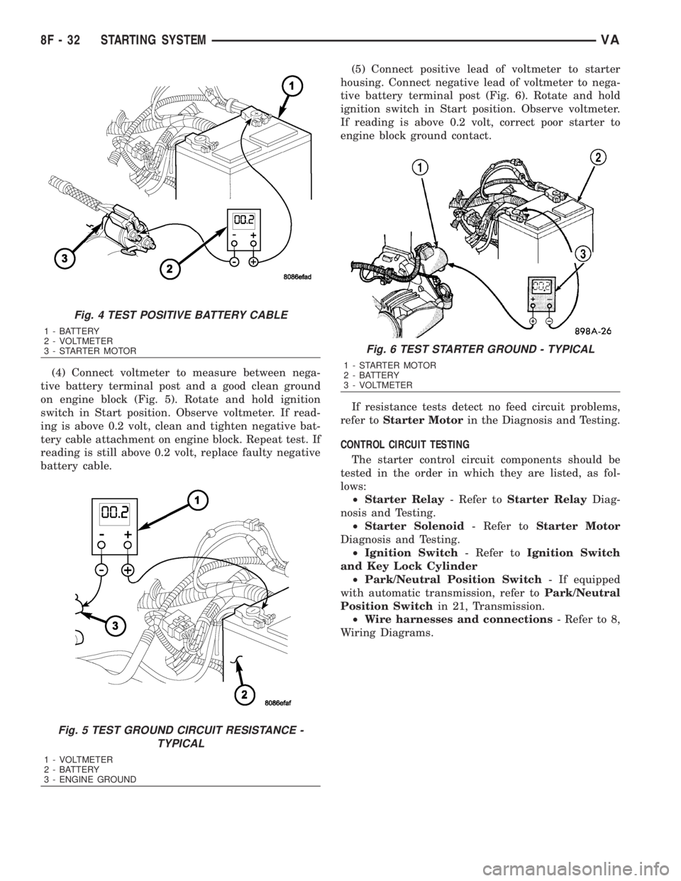
(4) Connect voltmeter to measure between nega-
tive battery terminal post and a good clean ground
on engine block (Fig. 5). Rotate and hold ignition
switch in Start position. Observe voltmeter. If read-
ing is above 0.2 volt, clean and tighten negative bat-
tery cable attachment on engine block. Repeat test. If
reading is still above 0.2 volt, replace faulty negative
battery cable.(5) Connect positive lead of voltmeter to starter
housing. Connect negative lead of voltmeter to nega-
tive battery terminal post (Fig. 6). Rotate and hold
ignition switch in Start position. Observe voltmeter.
If reading is above 0.2 volt, correct poor starter to
engine block ground contact.
If resistance tests detect no feed circuit problems,
refer toStarter Motorin the Diagnosis and Testing.
CONTROL CIRCUIT TESTING
The starter control circuit components should be
tested in the order in which they are listed, as fol-
lows:
²Starter Relay- Refer toStarter RelayDiag-
nosis and Testing.
²Starter Solenoid- Refer toStarter Motor
Diagnosis and Testing.
²Ignition Switch- Refer toIgnition Switch
and Key Lock Cylinder
²Park/Neutral Position Switch- If equipped
with automatic transmission, refer toPark/Neutral
Position Switchin 21, Transmission.
²Wire harnesses and connections- Refer to 8,
Wiring Diagrams.
Fig. 4 TEST POSITIVE BATTERY CABLE
1 - BATTERY
2 - VOLTMETER
3 - STARTER MOTOR
Fig. 5 TEST GROUND CIRCUIT RESISTANCE -
TYPICAL
1 - VOLTMETER
2 - BATTERY
3 - ENGINE GROUND
Fig. 6 TEST STARTER GROUND - TYPICAL
1 - STARTER MOTOR
2 - BATTERY
3 - VOLTMETER
8F - 32 STARTING SYSTEMVA
Page 921 of 2305
INSTRUMENT CLUSTER
DESCRIPTION
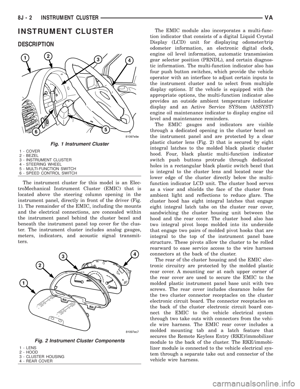
The instrument cluster for this model is an Elec-
troMechanical Instrument Cluster (EMIC) that is
located above the steering column opening in the
instrument panel, directly in front of the driver (Fig.
1). The remainder of the EMIC, including the mounts
and the electrical connections, are concealed within
the instrument panel behind the cluster bezel and
beneath the instrument panel top cover for the clus-
ter. The instrument cluster includes analog gauges,
meters, indicators, and acoustic signal transmit-
ters.The EMIC module also incorporates a multi-func-
tion indicator that consists of a digital Liquid Crystal
Display (LCD) unit for displaying odometer/trip
odometer information, an electronic digital clock,
engine oil level information, automatic transmission
gear selector position (PRNDL), and certain diagnos-
tic information. The multi-function indicator also has
four push button switches, which provide the vehicle
operator with an interface to adjust certain inputs to
the instrument cluster and to select from multiple
display options. If the vehicle is equipped with the
appropriate options, the multi-function indicator also
provides an outside ambient temperature indicator
display and an Active Service SYStem (ASSYST)
engine oil maintenance indicator to display engine oil
level and maintenance reminders.
The EMIC gauges and indicators are visible
through a dedicated opening in the cluster bezel on
the instrument panel and are protected by a clear
plastic cluster lens (Fig. 2) that is secured by eight
integral latches to the molded black plastic cluster
hood. Four, black plastic multi-function indicator
switch push buttons protrude through dedicated
holes in a rectangular black plastic switch bezel that
is integral to the cluster lens and located near the
lower edge of the cluster directly below the multi-
function indicator LCD unit. The cluster hood serves
as a visor and shields the face of the cluster from
ambient light and reflections to reduce glare. The
cluster hood has eight integral latches that engage
eight integral latch tabs on the cluster rear cover,
sandwiching the cluster housing unit between the
hood and the rear cover. The cluster hood also has
two integral pivot loops molded into its underside
that engage two pairs of molded pivot hooks that are
integral to the top of the instrument panel base
structure. These pivots allow the cluster to be rolled
rearward to ease service access to the wire harness
connectors at the back of the cluster.
The rear of the cluster housing and the EMIC elec-
tronic circuitry are protected by the molded plastic
rear cover. A mounting ear at each upper corner of
the rear cover are used to secure the EMIC to the
molded plastic instrument panel base unit with two
screws. The rear cover includes clearance holes for
the two cluster connector receptacles on the cluster
electronic circuit board. The connector receptacles on
the back of the cluster electronic circuit board con-
nect the EMIC to the vehicle electrical system
through two take outs with connectors from the vehi-
cle wire harness. The EMIC rear cover includes a
molded mounting tab and a latch feature that
secures the Remote Keyless Entry (RKE)/immobilizer
module to the back of the cluster. The RKE/immobi-
lizer module is connected to the vehicle electrical sys-
tem through a separate take out and connector of the
vehicle wire harness.
Fig. 1 Instrument Cluster
1 - COVER
2 - BEZEL
3 - INSTRUMENT CLUSTER
4 - STEERING WHEEL
5 - MULTI-FUNCTION SWITCH
6 - SPEED CONTROL SWITCH
Fig. 2 Instrument Cluster Components
1 - LENS
2 - HOOD
3 - CLUSTER HOUSING
4 - REAR COVER
8J - 2 INSTRUMENT CLUSTERVA
Page 925 of 2305

INDICATORS
Indicators are located in various positions within
the EMIC and are all connected to the EMIC elec-
tronic circuit board. The ambient temperature indica-
tor (optional), brake indicator, brake wear indicator,
charging indicator, coolant low indicator, high beam
indicator, low fuel indicator, park brake indicator,
seatbelt indicator, turn signal indicators, and washer
fluid indicator operate based upon hard wired inputs
to the EMIC. The airbag (SRS) indicator is normally
controlled by a hard wired input from the Airbag
Control Module (ACM); however, if the EMIC sees an
abnormal or no input from the ACM, it will automat-
ically turn the airbag indicator On until the hard
wired input from the ACM has been restored. The
Malfunction Indicator Lamp (MIL) is normally con-
trolled by CAN data bus messages from the Engine
Control Module (ECM); however, if the EMIC loses
CAN data bus communication, the EMIC circuitry
will automatically turn the MIL on until CAN data
bus communication is restored. The EMIC uses CAN
data bus messages from the ECM, the ACM, and the
Controller Antilock Brake to control all of the
remaining indicators.
The various EMIC indicators are controlled by dif-
ferent strategies; some receive battery feed from the
EMIC circuitry and have a switched ground, while
others are grounded through the EMIC circuitry and
have a switched battery feed. However, all indicators
are completely controlled by the EMIC microproces-
sor based upon various hard wired and electronic
message inputs. Except for the indications provided
by the multi-function indicator Liquid Crystal Dis-
play (LCD) unit, all indicators are illuminated at a
fixed intensity, which is not affected by the selected
illumination intensity of the EMIC general illumina-
tion lamps.
The hard wired indicator inputs may be diagnosed
using conventional diagnostic methods. However,
proper testing of the EMIC circuitry and the CAN
bus message controlled indicators requires the use of
a diagnostic scan tool. Refer to the appropriate diag-
nostic information. Specific details of the operation
for each indicator may be found elsewhere in this
service information.
CLUSTER ILLUMINATION
The EMIC has several general illumination lamps
that are illuminated when the exterior lighting is
turned on with the multi-function switch. The illumi-
nation intensity of these lamps is adjusted by a dim-
ming level input received from the multi-function
indicator ª+º (plus) and ª±º (minus) switch push but-
tons that extend through the lower edge of the clus-
ter lens below the right end of the multi-function
indicator. When the exterior lighting is turned Off,
the display is illuminated at maximum brightness.
When the exterior lighting is turned On and thetransmission gear selector is in the Park position,
depressing the plus switch push button brightens the
display lighting, and depressing the minus switch
push button dims the display lighting. The EMIC
also provides a Pulse-Width Modulated (PWM) panel
lamps dimmer output that can be used to synchro-
nize the illumination lighting levels of external illu-
mination lamps (up to about 23 to 30 watts) with
that of the EMIC.
The hard wired multi-function switch input and
the EMIC panel lamps dimmer output may be diag-
nosed using conventional diagnostic methods. How-
ever, proper testing of the PWM control of the EMIC
and the electronic dimming level inputs from the
multi-function indicator push buttons requires the
use of a diagnostic scan tool. Refer to the appropriate
diagnostic information.
INPUT AND OUTPUT CIRCUITS
HARD WIRED INPUTS
The hard wired inputs to the EMIC include the fol-
lowing:
NOTE: Final approved circuit names were not yet
available at the time this information was compiled.
²Airbag Indicator Driver
²Ambient Temperature Sensor Signal
(Optional)
²Brake Wear Indicator Sense
²Charging Indicator Driver
²Coolant Level Switch Sense
²Front Door Jamb Switch Sense
²Fuel Level Sensor Signal
²Fused B(+)
²Fused Ignition Switch Output
²High Beam Indicator Driver
²Key-In Ignition Switch Sense
²Left Turn Signal
²Park Brake Switch Sense
²Right Turn Signal
²Seat Belt Switch Sense
²Washer Fluid Switch Sense (Optional)
Refer to the appropriate wiring information for
additional details.
HARD WIRED OUTPUTS
The hard wired outputs of the EMIC include the
following:
²Engine Running Relay Control
²Panel Lamps Driver
Refer to the appropriate wiring information for
additional details.
8J - 6 INSTRUMENT CLUSTERVA
Page 937 of 2305

circuit board. The fuel gauge is serviced as a unit
with the instrument cluster.
OPERATION
The fuel gauge gives an indication to the vehicle
operator of the level of fuel in the fuel tank. This
gauge is controlled by the instrument cluster circuit
board based upon cluster programming and a hard
wired input received by the cluster from the fuel
level sensor in the fuel tank. The fuel gauge is an air
core magnetic unit that receives battery current on
the instrument cluster electronic circuit board when
the instrument cluster detects that the ignition
switch is in the On position. The cluster is pro-
grammed to move the gauge needle back to the low
end of the scale after the ignition switch is turned to
the Off position. The instrument cluster circuitry
controls the gauge needle position and provides the
following features:
²Fuel Level Sensor Input (At Ignition On)-
When the cluster detects the ignition switch has been
turned to the On position, the cluster moves the
gauge needle to the proper relative position on the
gauge scale as signaled by the fuel level sensor with-
out any electronic damping.
²Fuel Level Sensor Input (After Ignition On)
- After the ignition switch has been turned to the On
position, the cluster applies an algorithm to the input
from the fuel level sensor to electronically dampen
gauge needle movement against the negative effect
that fuel sloshing within the fuel tank can have on
accurate gauge readings.
²Fuel Level Sensor Input Open- If the fuel
level sensor input to the instrument cluster is an
open circuit, the cluster will move the fuel gauge nee-
dle to the ªEº (Empty) position on the gauge scale,
but the low fuel indicator will not be illuminated.
The fuel level sensor in the fuel tank provides a
hard wired input to the instrument cluster circuitry
through the fuel level sense circuit. The fuel level
sensor is a potentiometer that changes resistance
according to the fuel level. The instrument cluster
applies a fuel tank characteristic curve and fuel tank
reserve valve setting to the fuel level sensor input,
which must be configured when the cluster is initial-
ized. These characteristics determine the algorithm
the cluster uses to display the fuel level data on the
fuel gauge and the control for the low fuel warning
indicator. As the fuel level decreases, the resistance
through the fuel level sensor increases. The fuel level
sensor and the fuel level sense circuit to the instru-
ment cluster can be diagnosed using conventional
diagnostic tools and methods. For proper diagnosis of
the instrument cluster circuitry that controls the fuel
gauge, a diagnostic scan tool is required. Refer to the
appropriate diagnostic information.
GEAR SELECTOR INDICATOR
DESCRIPTION
An electronic automatic transmission gear selector
indicator is standard equipment on all instrument
clusters. The gear selector indicator information is
displayed in the center of the multi-function indicator
Liquid Crystal Display (LCD) located near the lower
edge of the instrument cluster, directly below the
speedometer. The gear selector indicator displays the
following characters as they are selected: ªP,º ªR,º
ªN,º ªD,º ª4,º ª3,º ª2,º and ª1.º Respectively, these
characters represent the currently selected park,
reverse, neutral, drive, fourth gear, third gear, second
gear, and first gear positions of the transmission gear
selector lever on the instrument panel.
The indications of the gear selector indicator are
not visible unless the multi-function indicator LCD is
illuminated and the engine is running. When illumi-
nated, each indication appears as a dark character
silhouetted against an amber field. When the exterior
lighting is turned Off, the display is illuminated at
maximum brightness. When the exterior lighting is
turned On, the display illumination level can be
adjusted in concert with the cluster general illumina-
tion lighting using the ª+º (plus) and ª2º (minus)
multi-function indicator push buttons. The gear
selector indicator is serviced as a unit with the
instrument cluster.
OPERATION
The electronic gear selector indicator gives an indi-
cation to the vehicle operator of the transmission
gear that is currently selected with the automatic
transmission gear selector lever. This indicator is
controlled by the instrument cluster circuit board
based upon cluster programming and electronic mes-
sages received from the Transmission Control Module
(TCM) over the Controller Area Network (CAN) data
bus. The gear selector indicator information is dis-
played by the multi-function indicator Liquid Crystal
Display (LCD) unit on the instrument cluster elec-
tronic circuit board. The multi-function indicator
LCD is completely controlled by the instrument clus-
ter logic circuit, and that logic will only allow the
gear selector indicator information to be displayed
when the instrument cluster detects that the ignition
switch is in the On position. Therefore, the gear
selector indicator will always be off when the ignition
switch is in any position except On.
The TCM continually monitors the transmission
range sensor, then sends the proper gear selector
indicator position messages to the instrument cluster.
For proper diagnosis of the transmission range sen-
sor, the TCM, the CAN data bus, or the electronic
message inputs to the instrument cluster that control
the gear selector indicator, a diagnostic scan tool is
8J - 18 INSTRUMENT CLUSTERVA
Page 1075 of 2305
OPERATION
The wiper motor operation is controlled by the
vehicle operator through battery current inputs
received by the wiper motor from the wiper switch
circuitry of the multi-function switch on the top of
the steering column, and from the wiper relay on the
fuse block underneath the steering column. The
wiper motor speed is controlled by current flow to
either the low speed or the high speed set of brushes.
The automatic resetting circuit breaker protects the
motor from overloads.
The park switch consists of a contact disc and
three contacts. The contact disc is mechanically fas-
tened to and rotated with a gear in the wiper motor
transmission. Two input contacts alternately close
the wiper park switch sense output circuit contact to
ground or to battery current, depending upon the
position of the wipers on the glass. This feature
allows the intermittent wipe logic circuit to monitor
the position and the cycles of the wiper motor to pro-
vide the intermittent wipe and wipe-after-wash
modes, as well as allowing the motor to complete its
current wipe cycle after the wiper system has been
turned Off and park the wiper blades in the lowest
portion of the wipe pattern.
The wiper motor may be diagnosed using conven-
tional diagnostic tools and methods.
REMOVAL
(1) Disconnect and isolate the battery negative
cable.
(2) Disconnect the vehicle wire harness connector
for the wiper motor from the motor pigtail wire con-
nector (Fig. 32).
8R - 32 WIPERS/WASHERSVA
Page 1086 of 2305
TERMINOLOGY
This is a list of terms and definitions used in the
wiring diagrams.
LHD.................Left Hand Drive Vehicles
RHD ...............Right Hand Drive Vehicles
ATX . . Automatic Transmissions-Front Wheel Drive
MTX . . . Manual Transmissions-Front Wheel Drive
AT....Automatic Transmissions-Rear Wheel Drive
MT .....Manual Transmissions-Rear Wheel Drive
SOHC...........Single Over Head Cam Engine
DOHC..........Double Over Head Cam Engine
Built-Up-Export....... Vehicles Built For Sale In
Markets Other Than North America
Except Built-Up-Export . Vehicles Built For Sale In
North America
CIRCUIT INFORMATION
Each wire shown in the diagrams contains a code
which identifies gage of wire, and color.
WIRE COLOR CODE CHART
COLOR CODE COLOR
BL BLUE
BK BLACK
BR BROWN
DB DARK BLUE
DG DARK GREEN
GY GRAY
LB LIGHT BLUE
LG LIGHT GREEN
OR ORANGE
PK PINK
RD RED
TN TAN
VT VIOLET
WT WHITE
YL YELLOW
* WITH TRACER
SECTION IDENTIFICATION AND INFORMATION
The wiring diagrams are grouped into individual
sections. If a component is most likely found in a par-
ticular group, it will be shown complete (all wires,
connectors, and pins) within that group. For exam-
ple, the Auto Shutdown Relay is most likely to be
found in Group 30, so it is shown there complete. It
can, however, be shown partially in another group if
it contains some associated wiring.
Splice diagrams in Section 8W-70 show the entire
splice and provide references to other sections thesplices serves. Section 8W-70 only contains splice dia-
grams that are not shown in their entirety some-
where else in the wiring diagrams.
Section 8W-80 shows each connector and the cir-
cuits involved with that connector. The connectors
are identified using the name/number on the dia-
gram pages.
WIRING SECTION CHART
GROUP TOPIC
8W-01 thru 8W-
09General information and Diagram
Overview
8W-10 thru 8W-
19Main Sources of Power and Ve-
hicle Grounding
8W-20 thru 8W-
29Starting and Charging
8W-30 thru 8W-
39Powertrain/Drivetrain Systems
8W-40 thru 8W-
49Body Electrical items and A/C
8W-50 thru 8W-
59Exterior Lighting, Wipers and
Trailer Tow
8W-60 thru 8W-
69Power Accessories
8W-70 Splice Information
8W-80 Connector Pin Outs
8W-91 Connector, Ground and Splice
Locations
CONNECTOR, GROUND, AND SPLICE INFOR-
MATION
CAUTION: Not all connectors are serviced. Some
connectors are serviced only with a harness. A typ-
ical example might be the Supplemental Restraint
System connectors. Always check parts availability
before attempting a repair.
IDENTIFICATION
In-line connectors are identified by a number, as
follows:
²In-line connectors located in the engine compart-
ment are C100 series numbers
²In-line connectors located in the Instrument
Panel area are C200 series numbers.
²In-line connectors located in the body are C300
series numbers.
²Jumper harness connectors are C400 series
numbers.
VA8W-01 WIRING DIAGRAM INFORMATION 8W - 01 - 5