2006 MERCEDES-BENZ SPRINTER drive belt
[x] Cancel search: drive beltPage 1014 of 2305
(10) Install and tighten the screw that secures the
front seat belt lower anchor to the outboard side of
the seat frame. Tighten the screw to 35 N´m (26 ft.
lbs.).
(11) If the vehicle is so equipped, snap the plastic
cover over the screw that secures the front seat belt
lower anchor to the outboard side of the seat frame.
(12) Do not reconnect the battery negative cable at
this time. The supplemental restraint system verifi-
cation test procedure should be performed following
service of any supplemental restraint system compo-
nent. (Refer to 8 - ELECTRICAL/RESTRAINTS -
STANDARD PROCEDURE - VERIFICATION TEST).
FRONT SEAT BELT BUCKLE
REMOVAL
WARNING: To avoid personal injury or death, during
and following any seat belt service, carefully
inspect all seat belts, buckles, mounting hardware,
retractors, and anchors for proper installation, oper-
ation, or damage. Replace any belt that is cut,
frayed, or torn. Straighten any belt that is twisted.
Tighten any loose fasteners. Replace any belt that
has a damaged or inoperative buckle or retractor.
Replace any belt that has a bent or damaged latch
plate or anchor plate. Never attempt to repair a seat
belt component. Always replace damaged or faulty
seat belt components with the correct, new and
unused replacement parts listed in the
DaimlerChrysler Mopar Parts Catalog.
(1) On the driver side only, move the seat to its
most forward position for easiest access to the seat
belt switch pigtail wire and connector.
(2) On the driver side only, remove the wire ties
that secure the seat belt switch pigtail wire to the
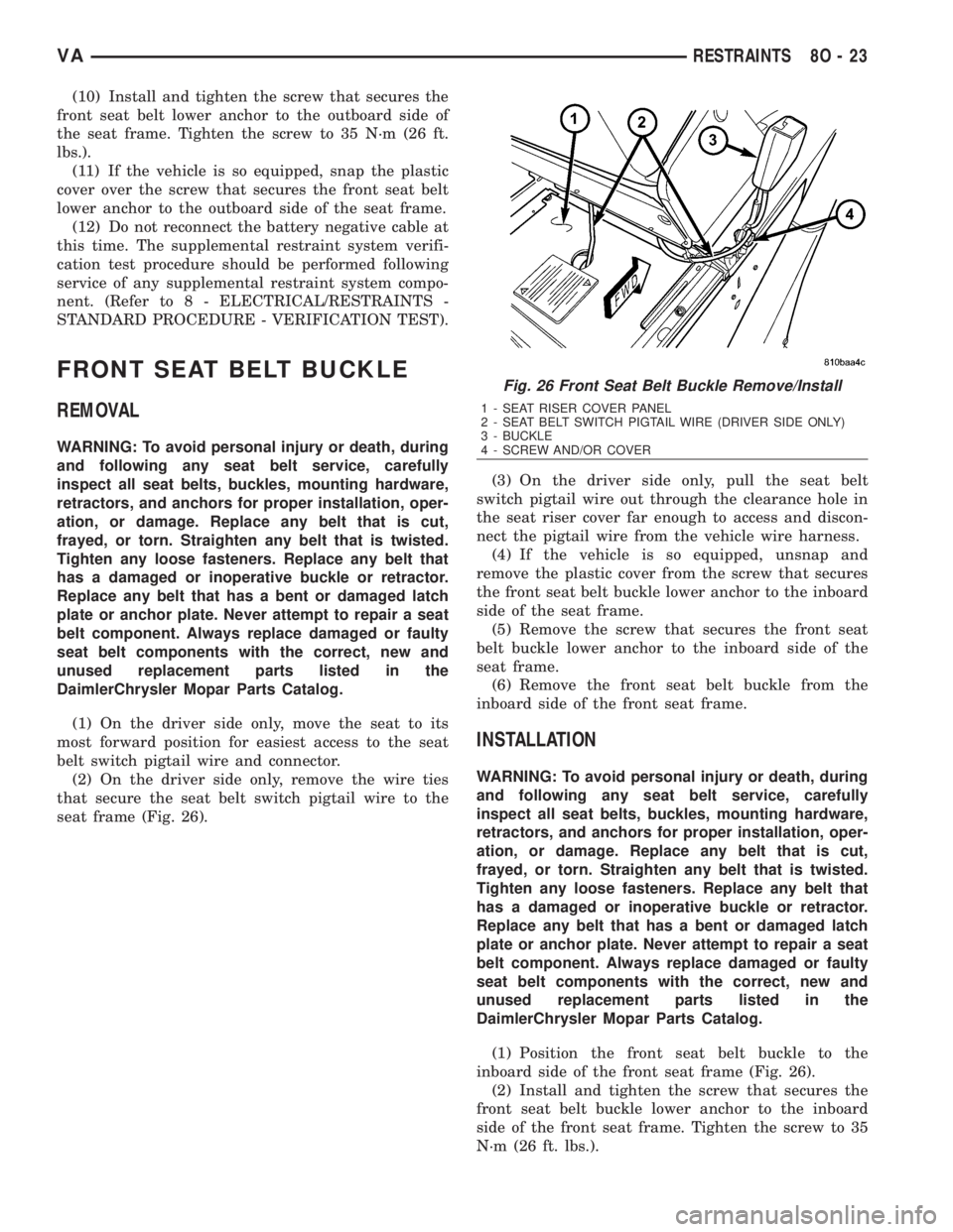
seat frame (Fig. 26).(3) On the driver side only, pull the seat belt
switch pigtail wire out through the clearance hole in
the seat riser cover far enough to access and discon-
nect the pigtail wire from the vehicle wire harness.
(4) If the vehicle is so equipped, unsnap and
remove the plastic cover from the screw that secures
the front seat belt buckle lower anchor to the inboard
side of the seat frame.
(5) Remove the screw that secures the front seat
belt buckle lower anchor to the inboard side of the
seat frame.
(6) Remove the front seat belt buckle from the
inboard side of the front seat frame.
INSTALLATION
WARNING: To avoid personal injury or death, during
and following any seat belt service, carefully
inspect all seat belts, buckles, mounting hardware,
retractors, and anchors for proper installation, oper-
ation, or damage. Replace any belt that is cut,
frayed, or torn. Straighten any belt that is twisted.
Tighten any loose fasteners. Replace any belt that
has a damaged or inoperative buckle or retractor.
Replace any belt that has a bent or damaged latch
plate or anchor plate. Never attempt to repair a seat
belt component. Always replace damaged or faulty
seat belt components with the correct, new and
unused replacement parts listed in the
DaimlerChrysler Mopar Parts Catalog.
(1) Position the front seat belt buckle to the
inboard side of the front seat frame (Fig. 26).
(2) Install and tighten the screw that secures the
front seat belt buckle lower anchor to the inboard
side of the front seat frame. Tighten the screw to 35
N´m (26 ft. lbs.).
Fig. 26 Front Seat Belt Buckle Remove/Install
1 - SEAT RISER COVER PANEL
2 - SEAT BELT SWITCH PIGTAIL WIRE (DRIVER SIDE ONLY)
3 - BUCKLE
4 - SCREW AND/OR COVER
VARESTRAINTS 8O - 23
Page 1015 of 2305
(3) If the vehicle is so equipped, snap the plastic
cover over the screw that secures the front seat belt
buckle lower anchor to the inboard side of the seat
frame.
(4) On the driver side only, reconnect the seat belt
switch pigtail wire to the vehicle wire harness and
push the joined connectors through the clearance
hole in the seat riser cover.
(5) On the driver side only, route and secure the
seat belt switch pigtail wire to the seat frame with
wire ties.
PASSENGER AIRBAG
DESCRIPTION
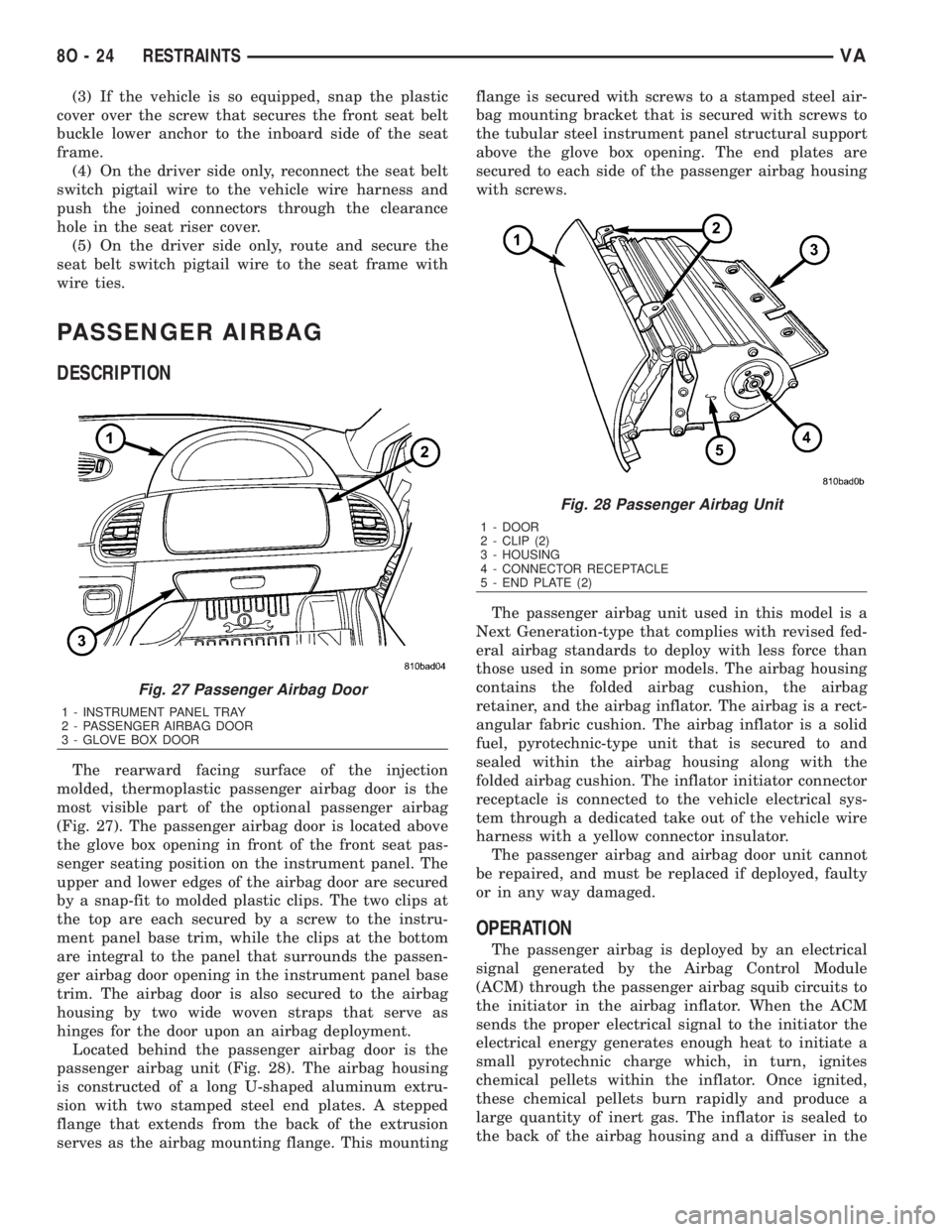
The rearward facing surface of the injection
molded, thermoplastic passenger airbag door is the
most visible part of the optional passenger airbag
(Fig. 27). The passenger airbag door is located above
the glove box opening in front of the front seat pas-
senger seating position on the instrument panel. The
upper and lower edges of the airbag door are secured
by a snap-fit to molded plastic clips. The two clips at
the top are each secured by a screw to the instru-
ment panel base trim, while the clips at the bottom
are integral to the panel that surrounds the passen-
ger airbag door opening in the instrument panel base
trim. The airbag door is also secured to the airbag
housing by two wide woven straps that serve as
hinges for the door upon an airbag deployment.
Located behind the passenger airbag door is the
passenger airbag unit (Fig. 28). The airbag housing
is constructed of a long U-shaped aluminum extru-
sion with two stamped steel end plates. A stepped
flange that extends from the back of the extrusion
serves as the airbag mounting flange. This mountingflange is secured with screws to a stamped steel air-
bag mounting bracket that is secured with screws to
the tubular steel instrument panel structural support
above the glove box opening. The end plates are
secured to each side of the passenger airbag housing
with screws.
The passenger airbag unit used in this model is a
Next Generation-type that complies with revised fed-
eral airbag standards to deploy with less force than
those used in some prior models. The airbag housing
contains the folded airbag cushion, the airbag
retainer, and the airbag inflator. The airbag is a rect-
angular fabric cushion. The airbag inflator is a solid
fuel, pyrotechnic-type unit that is secured to and
sealed within the airbag housing along with the
folded airbag cushion. The inflator initiator connector
receptacle is connected to the vehicle electrical sys-
tem through a dedicated take out of the vehicle wire
harness with a yellow connector insulator.
The passenger airbag and airbag door unit cannot
be repaired, and must be replaced if deployed, faulty
or in any way damaged.
OPERATION
The passenger airbag is deployed by an electrical
signal generated by the Airbag Control Module
(ACM) through the passenger airbag squib circuits to
the initiator in the airbag inflator. When the ACM
sends the proper electrical signal to the initiator the
electrical energy generates enough heat to initiate a
small pyrotechnic charge which, in turn, ignites
chemical pellets within the inflator. Once ignited,
these chemical pellets burn rapidly and produce a
large quantity of inert gas. The inflator is sealed to
the back of the airbag housing and a diffuser in the
Fig. 27 Passenger Airbag Door
1 - INSTRUMENT PANEL TRAY
2 - PASSENGER AIRBAG DOOR
3 - GLOVE BOX DOOR
Fig. 28 Passenger Airbag Unit
1 - DOOR
2 - CLIP (2)
3 - HOUSING
4 - CONNECTOR RECEPTACLE
5 - END PLATE (2)
8O - 24 RESTRAINTSVA
Page 1022 of 2305
REMOVAL - OUTBOARD
WARNING: To avoid personal injury or death, during
and following any seat belt service, carefully
inspect all seat belts, buckles, mounting hardware,
retractors, and anchors for proper installation, oper-
ation, or damage. Replace any belt that is cut,
frayed, or torn. Straighten any belt that is twisted.
Tighten any loose fasteners. Replace any belt that
has a damaged or inoperative buckle or retractor.
Replace any belt that has a bent or damaged latch
plate or anchor plate. Never attempt to repair a seat
belt component. Always replace damaged or faulty
seat belt components with the correct, new and
unused replacement parts listed in the
DaimlerChrysler Mopar Parts Catalog.
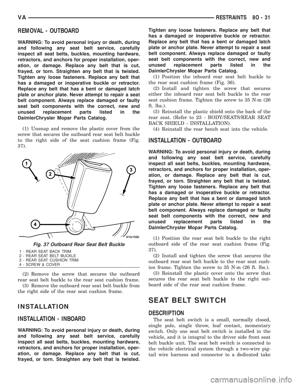
(1) Unsnap and remove the plastic cover from the
screw that secures the outboard rear seat belt buckle
to the right side of the seat cushion frame (Fig.
37).
(2) Remove the screw that secures the outboard
rear seat belt buckle to the rear seat cushion frame.
(3) Remove the outboard rear seat belt buckle from
the right side of the rear seat cushion frame.
INSTALLATION
INSTALLATION - INBOARD
WARNING: To avoid personal injury or death, during
and following any seat belt service, carefully
inspect all seat belts, buckles, mounting hardware,
retractors, and anchors for proper installation, oper-
ation, or damage. Replace any belt that is cut,
frayed, or torn. Straighten any belt that is twisted.Tighten any loose fasteners. Replace any belt that
has a damaged or inoperative buckle or retractor.
Replace any belt that has a bent or damaged latch
plate or anchor plate. Never attempt to repair a seat
belt component. Always replace damaged or faulty
seat belt components with the correct, new and
unused replacement parts listed in the
DaimlerChrysler Mopar Parts Catalog.
(1) Position the inboard rear seat belt buckle to
the rear seat cushion frame (Fig. 36).
(2) Install and tighten the screw that secures
either the inboard rear seat belt buckle to the rear
seat cushion frame. Tighten the screw to 35 N´m (26
ft. lbs.).
(3) Reinstall the plastic shield onto the back of the
rear seat. (Refer to 23 - BODY/SEATS/REAR SEAT
BACK SHIELD - INSTALLATION).
(4) Reinstall the rear bench seat into the vehicle.
INSTALLATION - OUTBOARD
WARNING: To avoid personal injury or death, during
and following any seat belt service, carefully
inspect all seat belts, buckles, mounting hardware,
retractors, and anchors for proper installation, oper-
ation, or damage. Replace any belt that is cut,
frayed, or torn. Straighten any belt that is twisted.
Tighten any loose fasteners. Replace any belt that
has a damaged or inoperative buckle or retractor.
Replace any belt that has a bent or damaged latch
plate or anchor plate. Never attempt to repair a seat
belt component. Always replace damaged or faulty
seat belt components with the correct, new and
unused replacement parts listed in the
DaimlerChrysler Mopar Parts Catalog.
(1) Position the rear seat belt buckle to the right
outboard side of the rear seat cushion frame (Fig.
37).
(2) Install and tighten the screw that secures the
outboard rear seat belt buckle to the rear seat cush-
ion frame. Tighten the screw to 35 N´m (26 ft. lbs.).
(3) Reinstall the plastic cover onto the screw that
secures the rear seat belt buckle to the right out-
board side of the rear seat cushion frame.
SEAT BELT SWITCH
DESCRIPTION
The seat belt switch is a small, normally closed,
single pole, single throw, leaf contact, momentary
switch. Only one seat belt switch is installed in the
vehicle, and it is integral to the driver side front seat
belt buckle unit. The seat belt switch is connected to
the vehicle electrical system through a two-wire pig-
tail wire harness and connector to a dedicated take
Fig. 37 Outboard Rear Seat Belt Buckle
1 - REAR SEAT BACK TRIM
2 - REAR SEAT BELT BUCKLE
3 - REAR SEAT CUSHION TRIM
4 - SCREW & COVER
VARESTRAINTS 8O - 31
Page 1023 of 2305
out and connector of the vehicle wire harness located
within the driver side front seat riser.
The seat belt switch cannot be adjusted or repaired
and, if faulty or damaged, the entire driver side seat
belt buckle unit must be replaced.
OPERATION
The seat belt switch is designed to control a path
to ground for the seat belt switch sense input of the
Electro-Mechanical Instrument Cluster (EMIC). The
seat belt switch contact is actuated by the seat belt
latch plate being inserted in to the buckle. When the
seat belt latch plate is inserted into the buckle far
enough to be engaged by the seat belt buckle latch,
the switch leaf contact opens the seat belt switch
sense circuit ground path; and, when the seat belt
latch plate is released and extracted from the seat
belt buckle latch the switch leaf contact is released,
closing the circuit to ground.
The seat belt switch is connected is series between
ground and the seat belt switch sense input of the
instrument cluster. The seat belt switch receives
ground at all times through its pigtail wire connec-
tion to the vehicle wire harness from another take
out of the vehicle wire harness. An eyelet terminal
connector on the vehicle wire harness ground take
out is secured under a nut to a ground stud located
on the floor panel within the driver side front seat
riser. The seat belt switch may de diagnosed using
conventional diagnostic tools and methods.
SEAT BELT TENSIONER
DESCRIPTION
Front seating position seat belt tensioners supple-
ment the standard driver and optional passenger air-
bags for all versions of this model. When equipped,
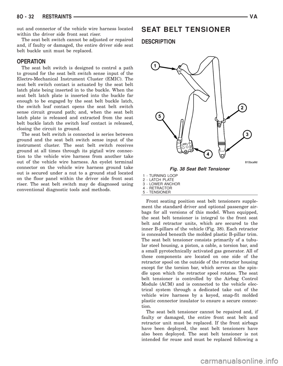
the seat belt tensioner is integral to the front seat
belt and retractor units, which are secured to the
inner B-pillars of the vehicle (Fig. 38). Each retractor
is concealed beneath the molded plastic B-pillar trim.
The seat belt tensioner consists primarily of a tubu-
lar steel housing, a piston, a cable, a torsion bar, and
a small pyrotechnically activated gas generator. All of
these components are located on one side of the
retractor spool on the outside of the retractor housing
except for the torsion bar, which serves as the spin-
dle upon which the retractor spool rotates. The seat
belt tensioner is controlled by the Airbag Control
Module (ACM) and is connected to the vehicle elec-
trical system through a dedicated take out of the
vehicle wire harness by a keyed, snap-fit molded
plastic connector insulator to ensure a secure connec-
tion.
The seat belt tensioner cannot be repaired and, if
faulty or damaged, the entire front seat belt and
retractor unit must be replaced. If the front airbags
have been deployed, the seat belt tensioners have
also been deployed. The seat belt tensioner is not
intended for reuse and must be replaced following a
Fig. 38 Seat Belt Tensioner
1 - TURNING LOOP
2 - LATCH PLATE
3 - LOWER ANCHOR
4 - RETRACTOR
5 - TENSIONER
8O - 32 RESTRAINTSVA
Page 1024 of 2305
deployment. A growling or grinding sound while
attempting to operate the seat belt retractor is a sure
indication that the seat belt tensioner has been
deployed and requires replacement. (Refer to 8 -
ELECTRICAL/RESTRAINTS/FRONT SEAT BELT &
RETRACTOR - REMOVAL).
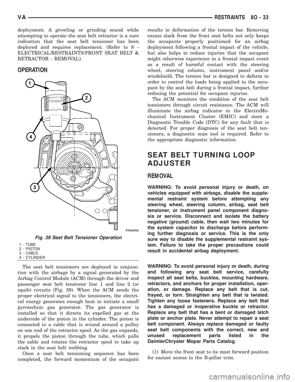
OPERATION
The seat belt tensioners are deployed in conjunc-
tion with the airbags by a signal generated by the
Airbag Control Module (ACM) through the driver and
passenger seat belt tensioner line 1 and line 2 (or
squib) circuits (Fig. 39). When the ACM sends the
proper electrical signal to the tensioners, the electri-
cal energy generates enough heat to initiate a small
pyrotechnic gas generator. The gas generator is
installed so that it directs its expelled gas at the
underside of the piston in the cylinder. The piston is
connected to a cable that is wound around a pulley
on one end of the retractor spool. As the gas expands,
it propels the piston through the tube, which pulls
the cable and rotates the retractor spool to take up
slack in the seat belt webbing.
Once a seat belt tensioning sequence has been
completed, the forward momentum of the occupantresults in deformation of the torsion bar. Removing
excess slack from the front seat belts not only keeps
the occupants properly positioned for an airbag
deployment following a frontal impact of the vehicle,
but also helps to reduce injuries that the occupant
might otherwise experience in a frontal impact event
as a result of harmful contact with the steering
wheel, steering column, instrument panel and/or
windshield. The torsion bar is designed to deform in
order to control the loads being applied to the occu-
pant by the seat belt during a frontal impact, further
reducing the potential for occupant injuries.
The ACM monitors the condition of the seat belt
tensioners through circuit resistance. The ACM will
illuminate the airbag indicator in the ElectroMe-
chanical Instrument Cluster (EMIC) and store a
Diagnostic Trouble Code (DTC) for any fault that is
detected. For proper diagnosis of the seat belt ten-
sioners, a diagnostic scan tool is required. Refer to
the appropriate diagnostic information.
SEAT BELT TURNING LOOP
ADJUSTER
REMOVAL
WARNING: To avoid personal injury or death, on
vehicles equipped with airbags, disable the supple-
mental restraint system before attempting any
steering wheel, steering column, airbag, seat belt
tensioner, or instrument panel component diagno-
sis or service. Disconnect and isolate the battery
negative (ground) cable, then wait two minutes for
the system capacitor to discharge before perform-
ing further diagnosis or service. This is the only
sure way to disable the supplemental restraint sys-
tem. Failure to take the proper precautions could
result in accidental airbag deployment.
WARNING: To avoid personal injury or death, during
and following any seat belt service, carefully
inspect all seat belts, buckles, mounting hardware,
retractors, and anchors for proper installation, oper-
ation, or damage. Replace any belt that is cut,
frayed, or torn. Straighten any belt that is twisted.
Tighten any loose fasteners. Replace any belt that
has a damaged or inoperative buckle or retractor.
Replace any belt that has a bent or damaged latch
plate or anchor plate. Never attempt to repair a seat
belt component. Always replace damaged or faulty
seat belt components with the correct, new and
unused replacement parts listed in the
DaimlerChrysler Mopar Parts Catalog.
(1) Move the front seat to its most forward position
for easiest access to the B-pillar trim.
Fig. 39 Seat Belt Tensioner Operation
1 - TUBE
2 - PISTON
3 - CABLE
4 - CYLINDER
VARESTRAINTS 8O - 33
Page 1025 of 2305

(2) Disconnect and isolate the battery negative
cable. Wait two minutes for the system capacitor to
discharge before further service.
(3) Remove the trim panel from the inside of the
B-pillar. (Refer to 23 - BODY/INTERIOR/B-PILLAR
TRIM - REMOVAL).
(4) Pull the height adjuster trim away from the
upper B-pillar to disengage the driver from the lug of
the height adjuster (Fig. 40).
(5) Remove the nut that secures the front seat belt
turning loop to the height adjuster (Fig. 41).(6) Remove the front seat belt turning loop from
the height adjuster.
(7) Remove the two screws that secure the seat
belt turning loop height adjuster to the upper inner
B-pillar (Fig. 42).
Fig. 40 Turning Loop Height Adjuster
1 - HEIGHT ADJUSTER TRIM
2 - LUG
3 - HEIGHT ADJUSTER
4 - DRIVER
Fig. 41 Front Seat Belt Turning Loop
1 - HEIGHT ADJUSTER
2 - NUT
3 - FRONT SEAT BELT
Fig. 42 Seat Belt Turning Loop Adjuster Remove/
Install
1 - SCREW (2)
2 - ADJUSTER
3 - B-PILLAR
8O - 34 RESTRAINTSVA
Page 1026 of 2305
(8) Remove the seat belt turning loop height
adjuster from the inner B-pillar.
INSTALLATION
WARNING: To avoid personal injury or death, on
vehicles equipped with airbags, disable the supple-
mental restraint system before attempting any
steering wheel, steering column, airbag, seat belt
tensioner, or instrument panel component diagno-
sis or service. Disconnect and isolate the battery
negative (ground) cable, then wait two minutes for
the system capacitor to discharge before perform-
ing further diagnosis or service. This is the only
sure way to disable the supplemental restraint sys-
tem. Failure to take the proper precautions could
result in accidental airbag deployment.
WARNING: To avoid personal injury or death, during
and following any seat belt service, carefully
inspect all seat belts, buckles, mounting hardware,
retractors, and anchors for proper installation, oper-
ation, or damage. Replace any belt that is cut,
frayed, or torn. Straighten any belt that is twisted.
Tighten any loose fasteners. Replace any belt that
has a damaged or inoperative buckle or retractor.
Replace any belt that has a bent or damaged latch
plate or anchor plate. Never attempt to repair a seat
belt component. Always replace damaged or faulty
seat belt components with the correct, new and
unused replacement parts listed in the
DaimlerChrysler Mopar Parts Catalog.
(1) Position the seat belt turning loop height
adjuster onto the inner B-pillar (Fig. 42).
(2) Install and tighten the two screws that secure
the seat belt turning loop height adjuster to the
upper inner B-pillar. Tighten the screws to 35 N´m
(26 ft. lbs.).
(3) Position the front seat belt turning loop onto
the height adjuster on the upper B-pillar (Fig. 41).
(4) Install and tighten the nut that secures the
front seat belt turning loop to the height adjuster.
Tighten the nut to 35 N´m (26 ft. lbs.).
(5) Position the height adjuster trim to the upper
B-pillar so that the driver on the back of the trim
engages the lug of the height adjuster (Fig. 40).
(6) Reinstall the trim panel onto the inside of the
B-pillar. (Refer to 23 - BODY/INTERIOR/B-PILLAR
TRIM - INSTALLATION).
(7) Reconnect the battery negative cable.
SIDE CURTAIN AIRBAG
DESCRIPTION
Optional side curtain airbags are available for this
model when it is also equipped with dual front air-
bags. These airbags are passive, inflatable, Supple-
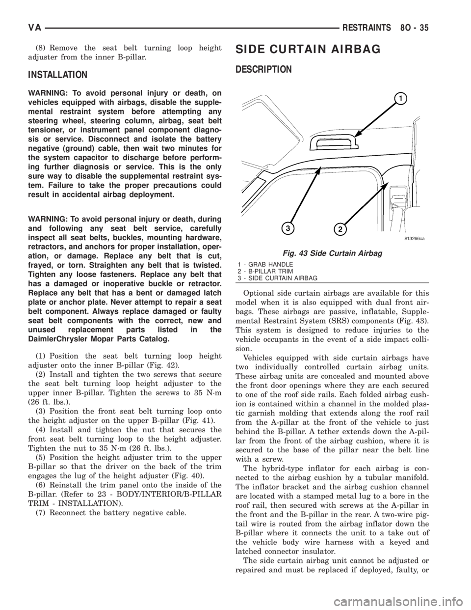
mental Restraint System (SRS) components (Fig. 43).
This system is designed to reduce injuries to the
vehicle occupants in the event of a side impact colli-
sion.
Vehicles equipped with side curtain airbags have
two individually controlled curtain airbag units.
These airbag units are concealed and mounted above
the front door openings where they are each secured
to one of the roof side rails. Each folded airbag cush-
ion is contained within a channel in the molded plas-
tic garnish molding that extends along the roof rail
from the A-pillar at the front of the vehicle to just
behind the B-pillar. A tether extends down the A-pil-
lar from the front of the airbag cushion, where it is
secured to the base of the pillar near the belt line
with a screw.
The hybrid-type inflator for each airbag is con-
nected to the airbag cushion by a tubular manifold.
The inflator bracket and the airbag cushion channel
are located with a stamped metal lug to a bore in the
roof rail, then secured with screws at the A-pillar in
the front and the B-pillar in the rear. A two-wire pig-
tail wire is routed from the airbag inflator down the
B-pillar where it connects the unit to a take out of
the vehicle body wire harness with a keyed and
latched connector insulator.
The side curtain airbag unit cannot be adjusted or
repaired and must be replaced if deployed, faulty, or
Fig. 43 Side Curtain Airbag
1 - GRAB HANDLE
2 - B-PILLAR TRIM
3 - SIDE CURTAIN AIRBAG
VARESTRAINTS 8O - 35
Page 1057 of 2305
(8) Reconnect the battery negative cable.
REMOVAL
WARNING: To avoid personal injury or death, on
vehicles equipped with airbags, disable the supple-
mental restraint system before attempting any
steering wheel, steering column, airbag, seat belt
tensioner, or instrument panel component diagno-
sis or service. Disconnect and isolate the battery
negative (ground) cable, then wait two minutes for
the system capacitor to discharge before perform-
ing further diagnosis or service. This is the only
sure way to disable the supplemental restraint sys-
tem. Failure to take the proper precautions could
result in accidental airbag deployment.
(1) Disconnect and isolate the battery negative
cable.
(2) Unsnap the base covers from each other and
remove them from the rear view mirror arm at the
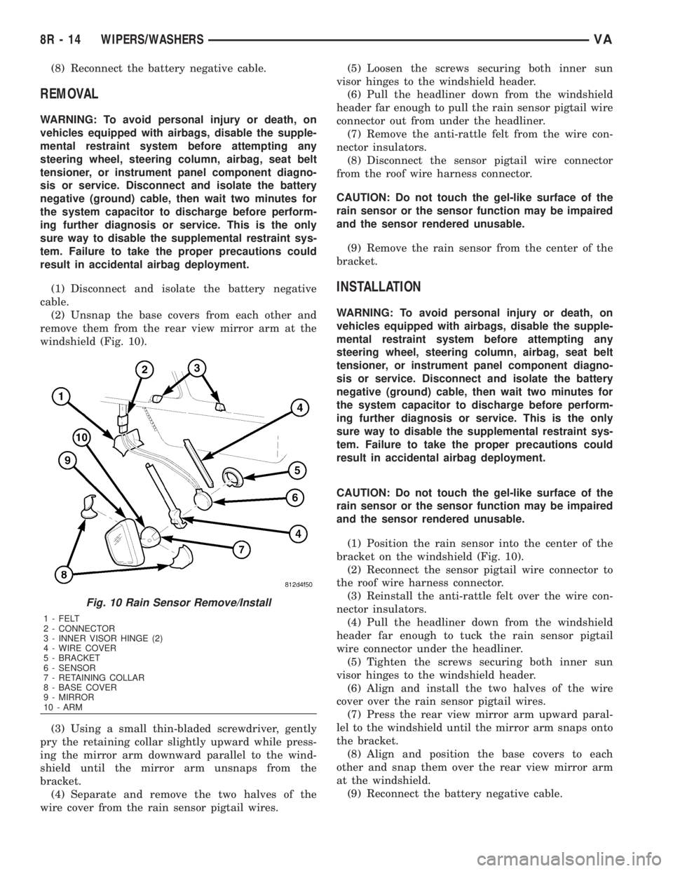
windshield (Fig. 10).
(3) Using a small thin-bladed screwdriver, gently
pry the retaining collar slightly upward while press-
ing the mirror arm downward parallel to the wind-
shield until the mirror arm unsnaps from the
bracket.
(4) Separate and remove the two halves of the
wire cover from the rain sensor pigtail wires.(5) Loosen the screws securing both inner sun
visor hinges to the windshield header.
(6) Pull the headliner down from the windshield
header far enough to pull the rain sensor pigtail wire
connector out from under the headliner.
(7) Remove the anti-rattle felt from the wire con-
nector insulators.
(8) Disconnect the sensor pigtail wire connector
from the roof wire harness connector.
CAUTION: Do not touch the gel-like surface of the
rain sensor or the sensor function may be impaired
and the sensor rendered unusable.
(9) Remove the rain sensor from the center of the
bracket.
INSTALLATION
WARNING: To avoid personal injury or death, on
vehicles equipped with airbags, disable the supple-
mental restraint system before attempting any
steering wheel, steering column, airbag, seat belt
tensioner, or instrument panel component diagno-
sis or service. Disconnect and isolate the battery
negative (ground) cable, then wait two minutes for
the system capacitor to discharge before perform-
ing further diagnosis or service. This is the only
sure way to disable the supplemental restraint sys-
tem. Failure to take the proper precautions could
result in accidental airbag deployment.
CAUTION: Do not touch the gel-like surface of the
rain sensor or the sensor function may be impaired
and the sensor rendered unusable.
(1) Position the rain sensor into the center of the
bracket on the windshield (Fig. 10).
(2) Reconnect the sensor pigtail wire connector to
the roof wire harness connector.
(3) Reinstall the anti-rattle felt over the wire con-
nector insulators.
(4) Pull the headliner down from the windshield
header far enough to tuck the rain sensor pigtail
wire connector under the headliner.
(5) Tighten the screws securing both inner sun
visor hinges to the windshield header.
(6) Align and install the two halves of the wire
cover over the rain sensor pigtail wires.
(7) Press the rear view mirror arm upward paral-
lel to the windshield until the mirror arm snaps onto
the bracket.
(8) Align and position the base covers to each
other and snap them over the rear view mirror arm
at the windshield.
(9) Reconnect the battery negative cable.
Fig. 10 Rain Sensor Remove/Install
1 - FELT
2 - CONNECTOR
3 - INNER VISOR HINGE (2)
4 - WIRE COVER
5 - BRACKET
6 - SENSOR
7 - RETAINING COLLAR
8 - BASE COVER
9 - MIRROR
10 - ARM
8R - 14 WIPERS/WASHERSVA