2006 MERCEDES-BENZ SPRINTER drive belt
[x] Cancel search: drive beltPage 1645 of 2305
(8) Install the exhaust hanger fasteners at the
muffler.
(9) Tighten the exhaust hanger bracket to engine
block.
(10) Install the turbocharger support bracket.
(11) Lower the vehicle.
(12) Install the air cleaner duct to the turbo-
charger (Fig. 71).
(13) Install the exhaust heat shield.
(14) Connect the negative battery cable.
TIMING CHAIN COVER
REMOVAL
WARNING: DO NOT OPEN COOLING SYSTEM
UNLESS TEMPERATURE IS BELOW 90ÉC (194ÉF).
OPEN CAP SLOWLY TO RELEASE PRESSURE.
STORE COOLANT IN APPROVED CONTAINER
ONLY. RISK OF INJURY TO SKIN AND EYES FROM
SCALDING COOLANT. WEAR PROTECTIVE
GLOVES, CLOTHING AND EYE WEAR.
(1) Disconnect negative battery cable.
NOTE: Rotate engine on crankshaft. DO NOT crank
the engine at the bolt of the camshaft sprocket.
NOTE: DO NOT crank engine back.
(2) Position piston of cylinder 1 to ignition TDC.
Markings on the camshaft bearing cap must be
aligned.
(3) Drain coolant (Refer to 7 - COOLING/ENGINE/
COOLANT - STANDARD PROCEDURE).
(4) Install retaining lock for crankshaft/starter
ring gear (Refer to 9 - ENGINE/ENGINE BLOCK/
FLEX PLATE - INSTALLATION).
(5) Drain engine oil.
(6) Remove the oil filter to allow the oil to flow off
into the oil pan.
(7) Remove the radiator assembly (Refer to 7 -
COOLING/ENGINE/RADIATOR - REMOVAL).
(8) Remove engine cover (Refer to 9 - ENGINE -
REMOVAL).
(9) Remove front cover at cylinder head (Refer to 9
- ENGINE/CYLINDER HEAD - REMOVAL).
(10) Remove accessory drive belt.
(11) Remove the high pressure fuel pump (Refer to
14 - FUEL SYSTEM/FUEL DELIVERY/FUEL PUMP
- REMOVAL).
(12) Remove water pump (Refer to 7 - COOLING/
ENGINE/WATER PUMP - REMOVAL).
(13) Remove accessory drive belt pulley and vibra-
tion damper (Refer to 9 - ENGINE/ENGINE BLOCK/
VIBRATION DAMPER - REMOVAL).
(14) Remove the power steering pump.NOTE: NO NOT open the air conditioning system.
(15) Unplug AC compressor electrical connector
and unbolt AC compressor. Relocate in lower engine
compartmentwith outopening the system.
(16) Remove the generator with wiring attached
and relocate somewhere in the engine compartment.
(17) Install engine support fixture.
(18) Remove the oil pan.
(19) Detach the coolant hose to oil-water heat
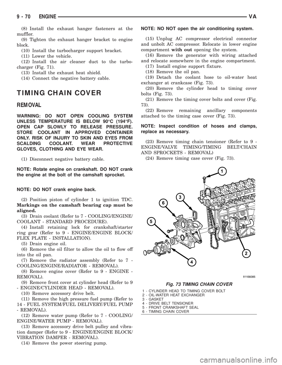
exchanger at crankcase (Fig. 73).
(20) Remove the cylinder head to timing cover
bolts (Fig. 73).
(21) Remove the timing cover bolts and cover (Fig.
73).
(22) Remove remaining ancillary components
attached to the timing case cover (Fig. 73).
NOTE: Inspect condition of hoses and clamps,
replace as necessary.
(23) Remove timing chain tensioner (Refer to 9 -
ENGINE/VALVE TIMING/TIMING BELT/CHAIN
AND SPROCKETS - REMOVAL)
(24) Remove timing case cover (Fig. 73).
Fig. 73 TIMING CHAIN COVER
1 - CYLINDER HEAD TO TIMING COVER BOLT
2 - OIL-WATER HEAT EXCHANGER
3 - GASKET
4 - DRIVE BELT TENSIONER
5 - FRONT CRANKSHAFT SEAL
6 - TIMING CHAIN COVER
9 - 70 ENGINEVA
Page 1646 of 2305
INSTALLATION
CAUTION: Care must be taken to closley inspect
the gasket area around the time case cover to cyl-
inder head gasket coolant port. If damage is found,
replace the cylinder head gasket. Failure to do so
may result in engine damage.
NOTE: Thoroughly clean all mating surfaces with
the appropriate solvents to assure that no grease or
oil is present during assembly.
(1) Inspect cylinder head gasket and oil pan gas-
ket. If damaged, replace.
(2) Replace the front crankshaft seal (Refer to 9 -
ENGINE/ENGINE BLOCK/CRANKSHAFT OIL
SEAL - FRONT - INSTALLATION).
(3) Install ancillary components to timing case
cover.
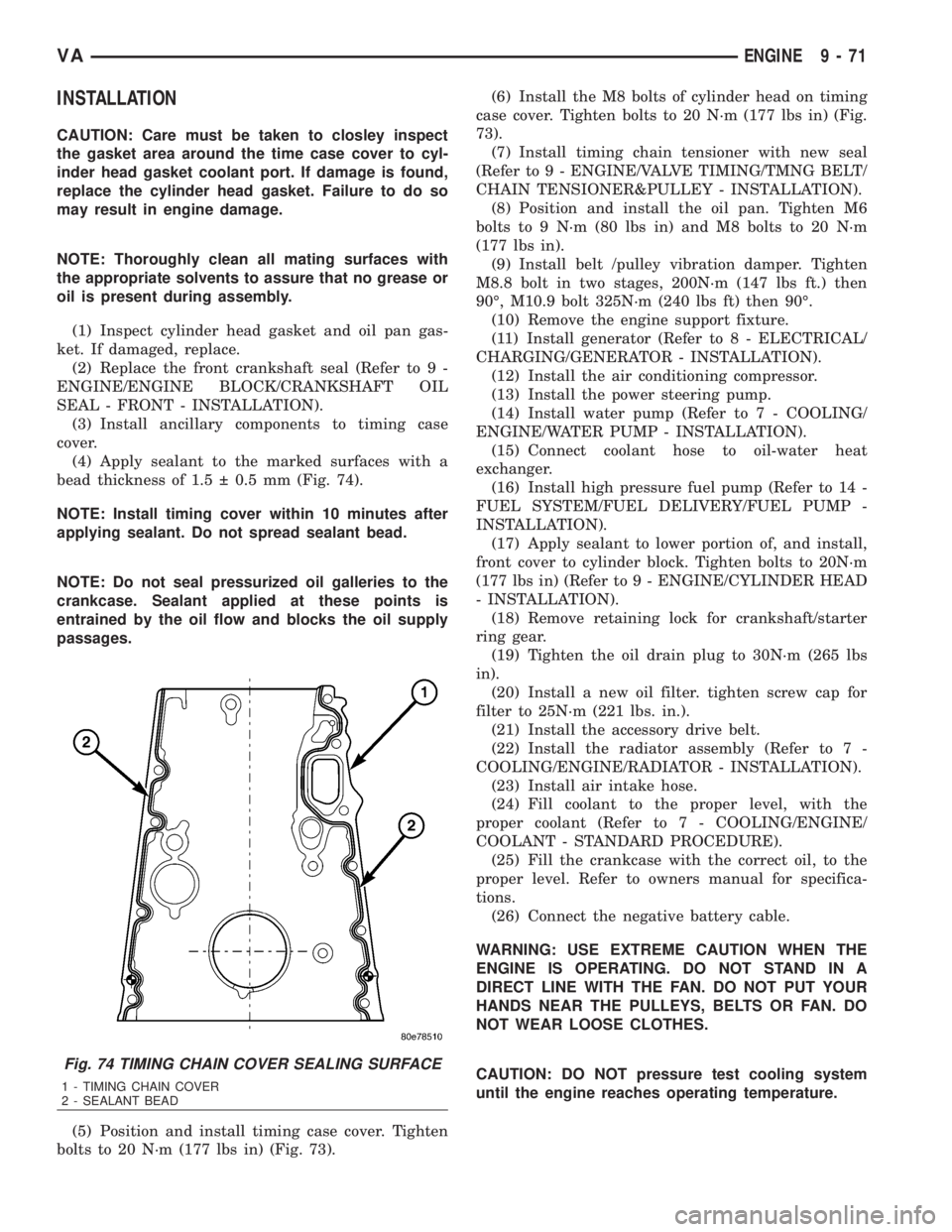
(4) Apply sealant to the marked surfaces with a
bead thickness of 1.5 0.5 mm (Fig. 74).
NOTE: Install timing cover within 10 minutes after
applying sealant. Do not spread sealant bead.
NOTE: Do not seal pressurized oil galleries to the
crankcase. Sealant applied at these points is
entrained by the oil flow and blocks the oil supply
passages.
(5) Position and install timing case cover. Tighten
bolts to 20 N´m (177 lbs in) (Fig. 73).(6) Install the M8 bolts of cylinder head on timing
case cover. Tighten bolts to 20 N´m (177 lbs in) (Fig.
73).
(7) Install timing chain tensioner with new seal
(Refer to 9 - ENGINE/VALVE TIMING/TMNG BELT/
CHAIN TENSIONER&PULLEY - INSTALLATION).
(8) Position and install the oil pan. Tighten M6
bolts to 9 N´m (80 lbs in) and M8 bolts to 20 N´m
(177 lbs in).
(9) Install belt /pulley vibration damper. Tighten
M8.8 bolt in two stages, 200N´m (147 lbs ft.) then
90É, M10.9 bolt 325N´m (240 lbs ft) then 90É.
(10) Remove the engine support fixture.
(11) Install generator (Refer to 8 - ELECTRICAL/
CHARGING/GENERATOR - INSTALLATION).
(12) Install the air conditioning compressor.
(13) Install the power steering pump.
(14) Install water pump (Refer to 7 - COOLING/
ENGINE/WATER PUMP - INSTALLATION).
(15) Connect coolant hose to oil-water heat
exchanger.
(16) Install high pressure fuel pump (Refer to 14 -
FUEL SYSTEM/FUEL DELIVERY/FUEL PUMP -
INSTALLATION).
(17) Apply sealant to lower portion of, and install,
front cover to cylinder block. Tighten bolts to 20N´m
(177 lbs in) (Refer to 9 - ENGINE/CYLINDER HEAD
- INSTALLATION).
(18) Remove retaining lock for crankshaft/starter
ring gear.
(19) Tighten the oil drain plug to 30N´m (265 lbs
in).
(20) Install a new oil filter. tighten screw cap for
filter to 25N´m (221 lbs. in.).
(21) Install the accessory drive belt.
(22) Install the radiator assembly (Refer to 7 -
COOLING/ENGINE/RADIATOR - INSTALLATION).
(23) Install air intake hose.
(24) Fill coolant to the proper level, with the
proper coolant (Refer to 7 - COOLING/ENGINE/
COOLANT - STANDARD PROCEDURE).
(25) Fill the crankcase with the correct oil, to the
proper level. Refer to owners manual for specifica-
tions.
(26) Connect the negative battery cable.
WARNING: USE EXTREME CAUTION WHEN THE
ENGINE IS OPERATING. DO NOT STAND IN A
DIRECT LINE WITH THE FAN. DO NOT PUT YOUR
HANDS NEAR THE PULLEYS, BELTS OR FAN. DO
NOT WEAR LOOSE CLOTHES.
CAUTION: DO NOT pressure test cooling system
until the engine reaches operating temperature.
Fig. 74 TIMING CHAIN COVER SEALING SURFACE
1 - TIMING CHAIN COVER
2 - SEALANT BEAD
VAENGINE 9 - 71
Page 1656 of 2305

TIMING CHAIN TENSIONER
REMOVAL
(1) Disconnect negative battery cable.
CAUTION: Rotate engine at crankshaft only. DO
NOT rotate the engine with the bolt of the camshaft
sprocket. DO NOT rotate the engine counter clock-
wise.
NOTE: Markings on the camshaft and camshaft
bearing cap must be aligned.
(2) Position piston of number 1 cylinder to ignition
TDC.
(3) Remove intake air duct.
(4) Remove accessory drive belt and idler pulley
above generator (Refer to 7 - COOLING/ACCES-
SORY DRIVE/DRIVE BELTS - REMOVAL).
(5) Remove timing chain tensioner (Fig. 91).
INSTALLATION
NOTE: Carefully clean all mating surfaces with
appropriate solvents to assure that no grease or oil
is present during reassembly.
(1) Install timing chain tensioner with new gasket.
Tighten to 80N´m (59 lbs.ft.).(2) Install idler pulley and accessory drive belt
(Refer to 7 - COOLING/ACCESSORY DRIVE/DRIVE
BELTS - INSTALLATION).
(3) Install intake air duct.
(4) Reconnect negative battery cable.
WARNING: USE EXTREME CAUTION WHEN THE
ENGINE IS OPERATING. DO NOT PUT YOUR
HANDS NEAR THE PULLEYS, BELTS OR FAN. DO
NOT WEAR LOOSE CLOTHES.
(5) Start the engine and inspect for leaks.
Fig. 91 TIMING CHAIN TENSIONER
1 - TIMING CHAIN TENSIONER
2 - TIMING CHAIN TENSIONER SEAL
VAENGINE 9 - 81
Page 1704 of 2305

(5) Tighten fuel rail bolts to 14 N´m (124 in. lbs.)
(Fig. 19)
CAUTION: When tightening fuel injection line union
nuts, counter hold with a wrench at the thread con-
nection. ON NO ACCOUNT exceed the tightening
torque at any time.
(6) Tighten the pressure line to the fuel rail to 20
N´m (177 in. lbs.).
(7) Tighten the high pressure fuel lines at the fuel
rail to 22 N´m (195 in. lbs.).
(8) Reconnect engine harness electrical connectors.
(9) Connect the intake manifold air inlet duct.
(10) Connect negative battery cable.
CAUTION: Care must be taken when installing the
engine cover. Assure the proper routing of the fuel
injector return fuel hose to the banjo bolt fitting in
the left rear corner of the cover. Failure to do so
may pinch or damage the hose causing fuel leakage
or a driveability concern.
WARNING: USE EXTREME CAUTION WHEN THE
ENGINE IS OPERATING. DO NOT STAND IN A
DIRECT LINE WITH FAN. DO NOT PUT YOUR
HANDS NEAR PULLEYS, BELTS OR FAN. DO NOT
WEAR LOOSE CLOTHING.
(11) Start engine, run for a few minutes, turn the
engine off and inspect for leaks (Refer to 14 - FUEL
SYSTEM - WARNING).
FUEL TANK
DESCRIPTION
The plastic fuel tank (Fig. 20) is mounted to the
frame rails under the left/center side of the vehicle.
The fuel tank contains a serviceable fuel pump mod-
ule with an electric fuel pump, and a fuel level send-
ing unit. The tank is also equipped with 2 fuel lines:
a fuel supply line to the fuel pump, and a separate
fuel return line.
Fuel Temperature Control:A section of the fuel
return line is coiled at the rear section of the tank
(Fig. 21). This coiled section is used to help drop the
temperature of fuel returning to the tank. A thermo-
stat (preheating valve) (3) (Fig. 21) is used to keep
fuel temperature below 167 degrees F. If fuel temper-
ature is above 167 degrees F, fuel passes first
through the coiled cooler lines, and then into the fuel
tank. If fuel temperature is below 150 degrees F, fuel
bypasses the coiled cooler lines, and is returned
directly into the fuel tank.
An electric fuel pump (more commonly referred to
in diesel applications as a fuel transfer pump or fuel
lift pump) is attached to the fuel pump module. Thismodule (Fig. 22) is located in the fuel tank. Refer to
Fuel Pump Module for additional information.
VAFUEL DELIVERY 14 - 23
Page 1730 of 2305
STEERING
TABLE OF CONTENTS
page page
STEERING
DESCRIPTION..........................1
OPERATION............................1
DIAGNOSIS AND TESTING - POWER
STEERING SYSTEM....................1COLUMN................................4
GEAR..................................7
LINKAGE................................9
PUMP..................................11
STEERING
DESCRIPTION
CAUTION: Use approved fluid only in the power
steering system (Refer to LUBRICATION & MAINTE-
NANCE/FLUID TYPES - DESCRIPTION). No other
power steering or automatic transmission fluid is to
be used in the system. Damage may result to the
power steering pump and system if any other fluid
is used, and do not overfill.
Power steering systems consist of:
²Steering column
²Rack and pinion steering gear
²Belt driven hydraulic steering pump
²Pump pressure and return hoses
²Oil Cooler
OPERATION
The steering column shaft is attached to the gear
pinion. The rotation of the pinion moves the gear
rack from side-to-side. This lateral action of the rack
pushes and pulls the tie rods to change the direction
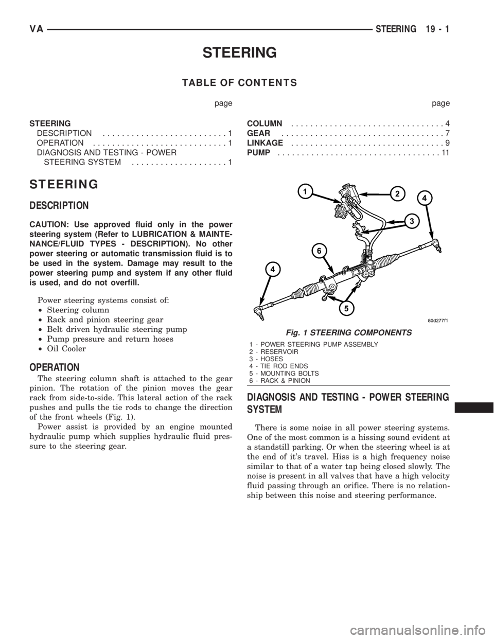
of the front wheels (Fig. 1).
Power assist is provided by an engine mounted
hydraulic pump which supplies hydraulic fluid pres-
sure to the steering gear.
DIAGNOSIS AND TESTING - POWER STEERING
SYSTEM
There is some noise in all power steering systems.
One of the most common is a hissing sound evident at
a standstill parking. Or when the steering wheel is at
the end of it's travel. Hiss is a high frequency noise
similar to that of a water tap being closed slowly. The
noise is present in all valves that have a high velocity
fluid passing through an orifice. There is no relation-
ship between this noise and steering performance.
Fig. 1 STEERING COMPONENTS
1 - POWER STEERING PUMP ASSEMBLY
2 - RESERVOIR
3 - HOSES
4 - TIE ROD ENDS
5 - MOUNTING BOLTS
6 - RACK & PINION
VASTEERING 19 - 1
Page 1740 of 2305
PUMP
TABLE OF CONTENTS
page page
PUMP
DESCRIPTION.........................11
OPERATION...........................11
DIAGNOSIS AND TESTING - PUMP LEAKAGE . 11
STANDARD PROCEDURE
STANDARD PROCEDURE - POWER
STEERING PUMP - INITIAL OPERATION....11
STANDARD PROCEDURE - FLUSHING
POWER STEERING SYSTEM............12
REMOVAL.............................12
INSTALLATION.........................12
SPECIFICATIONS - TORQUE CHART........13
FLUID
STANDARD PROCEDURE
POWER STEERING PUMP FILL AND BLEED
PROCEDURE........................13FLUID COOLER TUBE
REMOVAL.............................13
INSTALLATION.........................13
HOSES
REMOVAL
REMOVAL - PRESSURE HOSE...........14
REMOVAL - RETURN LINE FROM PUMP TO
COOLER TUBE.......................14
REMOVAL - RETURN HOSE FROM GEAR
TO COOLER TUBE....................14
INSTALLATION
INSTALLATION - PRESSURE HOSE.......14
INSTALLATION - RETURN LINE FROM
PUMP TO COOLER TUBE...............14
INSTALLATION - RETURN HOSE FROM
GEAR TO COOLER TUBE...............14
PUMP
DESCRIPTION
CAUTION: Use approved fluid only in the power
steering system (Refer to LUBRICATION & MAINTE-
NANCE/FLUID TYPES - DESCRIPTION). No other
power steering or automatic transmission fluid is to
be used in the system. Damage may result to the
power steering pump and system if any other fluid
is used, and do not overfill.
The pump is connected to the steering gear via the
pressure hose and the return hose. The pump shaft
has a pressed-on pulley that is belt driven by the
crankshaft pulley.
All vehicles are equipped with a power steering
fluid cooler.
NOTE: Power steering pumps are not interchange-
able with pumps installed on other vehicles.
OPERATION
Hydraulic pressure is provided for the power steer-
ing gear by the belt driven power steering pump. The
power steering pumps are constant flow rate and dis-
placement, vane-type pumps.
DIAGNOSIS AND TESTING - PUMP LEAKAGE
The pump is serviced as an assembly and should
not be disassembled. The plastic pump reservoir and
the reservoir o-rings can be replaced.Check for leaks in the following areas:
²Pump shaft seal behind the pulley
²Pump to reservoir O-ring
²Reservoir cap
²Pressure and return lines
²Flow control valve fitting
STANDARD PROCEDURE
STANDARD PROCEDURE - POWER STEERING
PUMP - INITIAL OPERATION
WARNING: THE FLUID LEVEL SHOULD BE
CHECKED WITH ENGINE OFF TO PREVENT INJURY
FROM MOVING COMPONENTS.
CAUTION: Use approved fluid only in the power
steering system (Refer to LUBRICATION & MAINTE-
NANCE/FLUID TYPES - DESCRIPTION). No other
power steering or automatic transmission fluid is to
be used in the system. Damage may result to the
power steering pump and system if any other fluid
is used, and do not overfill.
Wipe filler cap clean, then check the fluid level.
The dipstick should indicateCOLDwhen the fluid is
at normal temperature.
(1) Turn steering wheel all the way to the left
(2) Fill the pump fluid reservoir to the proper level
and let the fluid settle for at least two (2) minutes.
(3) Raise the front wheels off the ground.
VAPUMP 19 - 11
Page 2015 of 2305
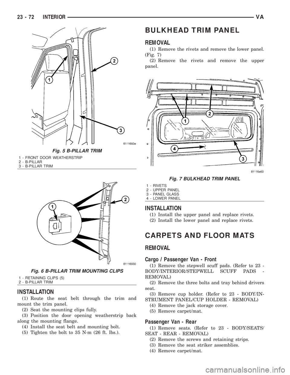
INSTALLATION
(1) Route the seat belt through the trim and
mount the trim panel.
(2) Seat the mounting clips fully.
(3) Position the door opening weatherstrip back
along the mounting flange.
(4) Install the seat belt and mounting bolt.
(5) Tighten the bolt to 35 N´m (26 ft. lbs.).
BULKHEAD TRIM PANEL
REMOVAL
(1) Remove the rivets and remove the lower panel.
(Fig. 7)
(2) Remove the rivets and remove the upper
panel.
INSTALLATION
(1) Install the upper panel and replace rivets.
(2) Install the lower panel and replace rivets.
CARPETS AND FLOOR MATS
REMOVAL
Cargo / Passenger Van - Front
(1) Remove the stepwell scuff pads. (Refer to 23 -
BODY/INTERIOR/STEPWELL SCUFF PADS -
REMOVAL)
(2) Remove the three bolts and tray behind drivers
seat.
(3) Remove cup holder. (Refer to 23 - BODY/IN-
STRUMENT PANEL/CUP HOLDER - REMOVAL)
(4) Remove the jack storage cover.
(5) Remove carpet/mat.
Passenger Van - Rear
(1) Remove seats. (Refer to 23 - BODY/SEATS/
SEAT - REAR - REMOVAL)
(2) Remove the screws and retaining strips.
(3) Remove the seat striker assemblies.
(4) Remove carpet/mat.
Fig. 5 B-PILLAR TRIM
1 - FRONT DOOR WEATHERSTRIP
2 - B-PILLAR
3 - B-PILLAR TRIM
Fig. 6 B-PILLAR TRIM MOUNTING CLIPS
1 - RETAINING CLIPS (5)
2 - B-PILLAR TRIM
Fig. 7 BULKHEAD TRIM PANEL
1 - RIVETS
2 - UPPER PANEL
3 - PANEL GLASS
4 - LOWER PANEL
23 - 72 INTERIORVA
Page 2042 of 2305
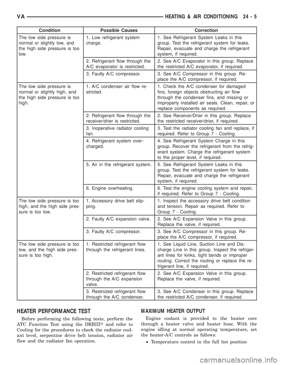
Condition Possible Causes Correction
The low side pressure is
normal or slightly low, and
the high side pressure is too
low.1. Low refrigerant system
charge.1. See Refrigerant System Leaks in this
group. Test the refrigerant system for leaks.
Repair, evacuate and charge the refrigerant
system, if required.
2. Refrigerant flow through the
A/C evaporator is restricted.2. See A/C Evaporator in this group. Replace
the restricted A/C evaporator, if required.
3. Faulty A/C compressor. 3. See A/C Compressor in this group. Re-
place the A/C compressor, if required.
The low side pressure is
normal or slightly high, and
the high side pressure is too
high.1. A/C condenser air flow re-
stricted.1. Check the A/C condenser for damaged
fins, foreign objects obstructing air flow
through the condenser fins, and missing or
improperly installed air seals. Clean, repair, or
replace components as required.
2. Refrigerant flow through the
receiver/drier is restricted.2. See Receiver/Drier in this group. Replace
the restricted receiver/drier, if required.
3. Inoperative radiator cooling
fan.3. Test the radiator cooling fan and replace, if
required. Refer to Group 7 - Cooling.
4. Refrigerant system over-
charged.4. See Refrigerant System Charge in this
group. Recover the refrigerant from the refrig-
erant system. Charge the refrigerant system
to the proper level, if required.
5. Air in the refrigerant system. 5. See Refrigerant System Leaks in this
group. Test the refrigerant system for leaks.
Repair, evacuate and charge the refrigerant
system, if required.
6. Engine overheating. 6. Test the engine cooling system and repair,
if required. Refer to Group 7 - Cooling.
The low side pressure is too
high, and the high side pres-
sure is too low.1. Accessory drive belt slip-
ping.1. Inspect the accessory drive belt condition
and tension. Repair as required. Refer to
Group 7 - Cooling.
2. Faulty A/C expansion valve. 2. See A/C Expansion Valve in this group.
Replace the valve, if required.
3. Faulty A/C compressor. 3. See A/C Compressor in this group. Re-
place the A/C compressor, if required.
The low side pressure is too
low, and the high side pres-
sure is too high.1. Restricted refrigerant flow
through the refrigerant lines.1. See Liquid Line, Suction Line and Dis-
charge Line in this group. Inspect the refriger-
ant lines for kinks, tight bends or improper
routing. Correct the routing or replace the re-
frigerant line, if required.
2. Restricted refrigerant flow
through the A/C expansion
valve.2. See A/C Expansion Valve in this group.
Replace the valve, if required.
3. Restricted refrigerant flow
through the A/C condenser.3. See A/C Condenser in this group. Replace
the restricted A/C condenser, if required.
HEATER PERFORMANCE TEST
Before performing the following tests, perform the
ATC Function Test using the DRBIIItand refer to
Cooling for the procedures to check the radiator cool-
ant level, serpentine drive belt tension, radiator air
flow and the radiator fan operation.
MAXIMUM HEATER OUTPUT
Engine coolant is provided to the heater core
through a heater valve and heater hose. With the
engine idling at normal operating temperature, set
the heater-A/C controls as follows:
²Temperature control in the full hot position
VAHEATING & AIR CONDITIONING 24 - 5