2006 MERCEDES-BENZ SPRINTER drive belt
[x] Cancel search: drive beltPage 2046 of 2305
OPERATION
The compressor clutch components provide the
means to engage and disengage the compressor from
the engine serpentine accessory drive belt. When the
clutch coil is energized, it magnetically draws the
clutch into contact with the pulley and drives the
compressor shaft. When the coil is not energized, the
pulley freewheels on the clutch hub bearing, which is
part of the pulley.
The compressor clutch engagement is controlled by
several components:
²A/C switch on the A/C-heater control panel
²Evaporator temperature sensor
²A/C pressure transducer
²Air temperature sensor
²CAN bus messages
The compressor clutch is de-energized under any of
the following conditions:
²Blocked compressor (thermal fuse in the pulley)
²Low pressure in the system
²Low evaporator temperature
²Hard acceleration (WOT)
²High coolant temperatures
STANDARD PROCEDURE
A / C COMPRESSOR CLUTCH AIR GAP
If a new clutch plate and/or clutch pulley are being
used, the air gap between the clutch plate and clutch
pulley must be checked using the following proce-
dure:
(1) Using feeler gauges, measure the air gap
between the clutch plate and the clutch pulley fric-
tion surfaces.
(2) If the air gap is not between specifications
(Refer to 24 - HEATING & AIR CONDITIONING -
SPECIFICATIONS), add or subtract shims until the
desired air gap is obtained.
NOTE: The shims may compress after tightening
the compressor shaft bolt. Check the air gap in four
or more places on the clutch plate to verify that the
air gap is still correct. Spin the clutch pulley before
making the final air gap check.
A / C COMPRESSOR CLUTCH BREAK - IN
After a new compressor clutch has been installed,
cycle the compressor clutch approximately twenty
times (five seconds on, then five seconds off). During
this procedure, set the heater-A/C control in the
Recirculation Mode, the A/C button in the on posi-
tion, the blower motor switch in the highest speed
position, and the engine speed at 1500 to 2000 rpm.
This procedure (burnishing) will seat the opposing
friction surfaces and provide a higher compressor
clutch torque capability.
REMOVAL
The refrigerant system can remain fully-charged
during compressor clutch, pulley, or coil replacement.
The compressor clutch can be serviced in the vehicle.
(1) Disconnect and isolate the battery negative
cable.
(2) Remove the serpentine drive belt (Refer to 7 -
COOLING/ACCESSORY DRIVE/DRIVE BELTS -
REMOVAL).
(3) Disconnect the engine wire harness connector
for the compressor clutch coil from the clutch coil
wire harness connector on the top of the compressor.
(4) Remove the retainer securing the compressor
clutch coil lead on the top of the compressor.
(5) Remove the bolt that secures the compressor
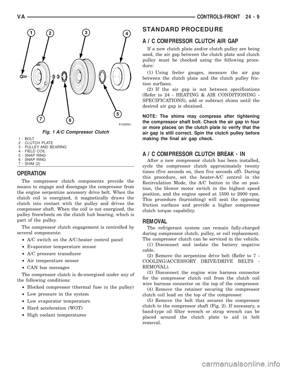
clutch to the compressor shaft (Fig. 2). If necessary, a
band-type oil filter wrench or strap wrench can be
placed around the clutch plate to aid in bolt
removal.
Fig. 1 A/C Compressor Clutch
1 - BOLT
2 - CLUTCH PLATE
3 - PULLEY AND BEARING
4 - FIELD COIL
5 - SNAP RING
6 - SNAP RING
7 - SHIM (2)
VACONTROLS-FRONT 24 - 9
Page 2049 of 2305
front cover of the compressor. Be certain that the
snap ring is properly fully and properly seated in the
groove.
(6) If the original clutch plate and clutch pulley
are to be reused, reinstall the original shim(s) on the
compressor shaft against the shoulder. If a new
clutch plate and/or clutch pulley are being used,
install a trial stack of shims 1.0 mm (0.040 in.) thick
on the compressor shaft against the shoulder.
(7) Install the clutch plate onto the compressor
shaft.
(8) Install and tighten the compressor shaft bolt. If
necessary, a band-type oil filter wrench or a strap
wrench can be placed around the clutch plate to aid
in bolt tightening. Tighten the bolt to 17.5 N´m (155
in. lbs.).
NOTE: The shims may compress after tightening
the shaft bolt. Check the air gap in four or more
places to verify the air gap is still correct. Spin the
pulley before performing a final check of the air
gap.
(9) If a new clutch plate and/or clutch pulley are
being installed, the air gap between the clutch plate
and clutch pulley must be checked (Refer to 24 -
HEATING & AIR CONDITIONING/CONTROLS/A/C
COMPRESSOR CLUTCH - STANDARD PROCE-
DURE).
(10) Install the retainer that secures the compres-
sor clutch coil lead to the top of the compressor.
(11) Reconnect the engine wire harness connector
to the clutch coil lead on the top of the compressor.
(12) Reinstall the serpentine accessory drive belt
(Refer to 7 - COOLING/ACCESSORY DRIVE/DRIVE
BELTS - INSTALLATION).
(13) Reconnect the battery negative cable.
(14) If a new clutch plate and/or clutch pulley are
being installed, the new clutch components must be
burnished (Refer to 24 - HEATING & AIR CONDI-
TIONING/CONTROLS/A/C COMPRESSOR CLUTCH
- STANDARD PROCEDURE).
A / C COMPRESSOR CLUTCH
COIL
DIAGNOSIS AND TESTING
A / C COMPRESSOR CLUTCH COIL
The air conditioning compressor clutch coil electri-
cal circuit is controlled by the ATC control module
which is integral to the heater-A/C control. Begin
testing of a suspected compressor clutch coil problem
by performing the ATC Function Test using the
DRBIIItscan tool.PRELIMINARY CHECKS
(1) If no diagnostic trouble codes (DTCs) are found
in the A/C-heater control or the powertrain control
module (PCM), go to Step 2. If any DTCs are found,
repair as required.
(2) If the A/C compressor clutch still will not
engage, verify the refrigerant charge level (Refer to
24 - HEATING & AIR CONDITIONING/PLUMBING
- DIAGNOSIS AND TESTING - REFRIGERANT
SYSTEM LEAKS). If the refrigerant charge level is
OK, go to TESTS. If the refrigerant charge level is
not OK, adjust the refrigerant charge as required.
TESTS
(1) Verify the battery state of charge (Refer to 8 -
ELECTRICAL/BATTERY SYSTEM/BATTERY -
DIAGNOSIS AND TESTING).
(2) Connect an ammeter (0 to 10 ampere scale
selected) in series with the clutch coil feed terminal.
Connect a voltmeter (0 to 20 volt scale selected) to
measure voltage across the battery and the clutch
coil.
(3) With the A/C-heater control in the A/C mode
and the blower motor at low speed, start the engine
and allow it to run at a normal idle speed.
(4) The A/C compressor clutch should engage
immediately, and the clutch coil supply voltage
should be within two volts of the battery voltage. If
the coil supply voltage is OK, go to Step 5. If the coil
supply voltage is not within two volts of battery volt-
age, test the clutch coil feed circuit for excessive volt-
age drop and repair as necessary.
(5) For the acceptable A/C clutch coil current draw
specifications refer to 24 - HEATING & AIR CONDI-
TIONING - SPECIFICATIONS. Specifications apply
for a work area temperature of 21É C (70É F). If volt-
age is more than 12.5 volts, add electrical loads by
turning on electrical accessories until voltage reads
below 12.5 volts.
(a) If the A/C clutch coil current reading is zero,
the coil is open and must be replaced.
(b) If the A/C clutch coil current reading is above
specifications, the coil is shorted and must be
replaced.
A / C HEATER CONTROL
DESCRIPTION
This ATC system uses a combination of electrical
and mechanical controls. These controls provide the
vehicle operator with a number of setting options to
help control the climate and comfort within the vehi-
cle.
The A/C-heater control is located on the instrument
panel inboard of the steering column and below the
24 - 12 CONTROLS-FRONTVA
Page 2082 of 2305
DISTRIBUTION - FRONT
TABLE OF CONTENTS
page page
AIR FILTER
REMOVAL.............................45
INSTALLATION.........................45
AIR OUTLETS
REMOVAL.............................45
INSTALLATION.........................46
BLOWER MOTOR
REMOVAL.............................47
INSTALLATION.........................47
DEFROSTER DUCTS
REMOVAL.............................47
INSTALLATION.........................47FLOOR DISTRIBUTION DUCTS
REMOVAL.............................47
INSTALLATION.........................48
HVAC HOUSING
REMOVAL.............................48
DISASSEMBLY.........................49
ASSEMBLY............................50
INSTALLATION.........................50
INSTRUMENT PANEL DUCTS
REMOVAL.............................51
INSTALLATION.........................51
AIR FILTER
REMOVAL
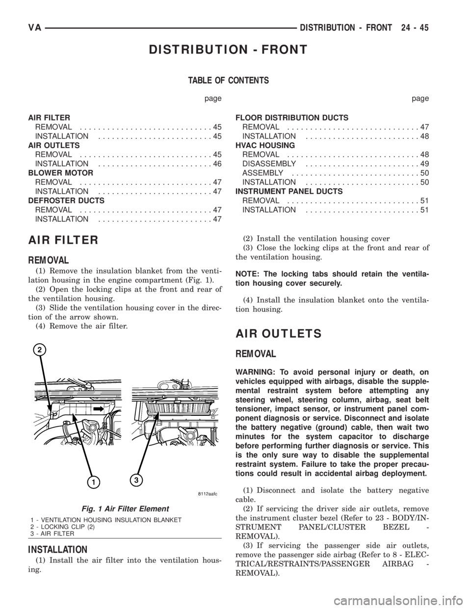
(1) Remove the insulation blanket from the venti-
lation housing in the engine compartment (Fig. 1).
(2) Open the locking clips at the front and rear of
the ventilation housing.
(3) Slide the ventilation housing cover in the direc-
tion of the arrow shown.
(4) Remove the air filter.
INSTALLATION
(1) Install the air filter into the ventilation hous-
ing.(2) Install the ventilation housing cover
(3) Close the locking clips at the front and rear of
the ventilation housing.
NOTE: The locking tabs should retain the ventila-
tion housing cover securely.
(4) Install the insulation blanket onto the ventila-
tion housing.
AIR OUTLETS
REMOVAL
WARNING: To avoid personal injury or death, on
vehicles equipped with airbags, disable the supple-
mental restraint system before attempting any
steering wheel, steering column, airbag, seat belt
tensioner, impact sensor, or instrument panel com-
ponent diagnosis or service. Disconnect and isolate
the battery negative (ground) cable, then wait two
minutes for the system capacitor to discharge
before performing further diagnosis or service. This
is the only sure way to disable the supplemental
restraint system. Failure to take the proper precau-
tions could result in accidental airbag deployment.
(1) Disconnect and isolate the battery negative
cable.
(2) If servicing the driver side air outlets, remove
the instrument cluster bezel (Refer to 23 - BODY/IN-
STRUMENT PANEL/CLUSTER BEZEL -
REMOVAL).
(3) If servicing the passenger side air outlets,
remove the passenger side airbag (Refer to 8 - ELEC-
TRICAL/RESTRAINTS/PASSENGER AIRBAG -
REMOVAL).
Fig. 1 Air Filter Element
1 - VENTILATION HOUSING INSULATION BLANKET
2 - LOCKING CLIP (2)
3 - AIR FILTER
VADISTRIBUTION - FRONT 24 - 45
Page 2103 of 2305
(12)EXAMPLE:The ambient temperature is 21É
C (70É F). The evaporator inlet tube temperature is
12É C (54É F) and the evaporator outlet tube temper-
ature is 10É C (50É F). Subtract the inlet tube tem-
perature from the outlet tube temperature. The
difference is -2É C (-4É F). With a -2É C (-4É F) tem-
perature differential at 21É C (70É F) ambient tem-
perature, the system is fully charged.
(13) Add enough refrigerant to bring the refriger-
ant system up to a full charge.
(14) Remove the jumper wire from the low pres-
sure cycling clutch switch wire harness connector
and plug the connector back into the switch.
A / C COMPRESSOR
DESCRIPTION
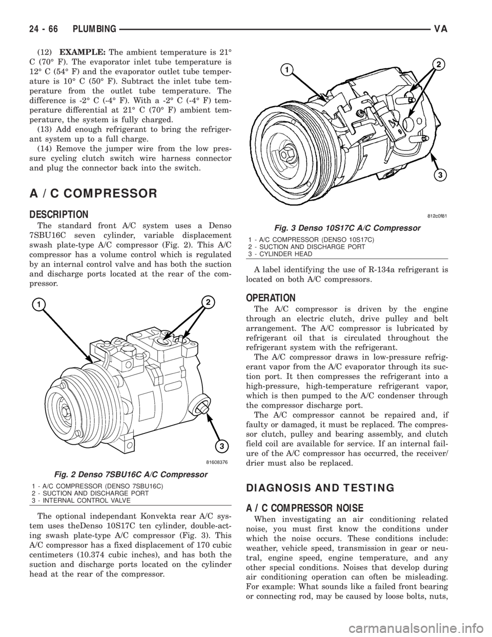
The standard front A/C system uses a Denso
7SBU16C seven cylinder, variable displacement
swash plate-type A/C compressor (Fig. 2). This A/C
compressor has a volume control which is regulated
by an internal control valve and has both the suction
and discharge ports located at the rear of the com-
pressor.
The optional independant Konvekta rear A/C sys-
tem uses theDenso 10S17C ten cylinder, double-act-
ing swash plate-type A/C compressor (Fig. 3). This
A/C compressor has a fixed displacement of 170 cubic
centimeters (10.374 cubic inches), and has both the
suction and discharge ports located on the cylinder
head at the rear of the compressor.A label identifying the use of R-134a refrigerant is
located on both A/C compressors.
OPERATION
The A/C compressor is driven by the engine
through an electric clutch, drive pulley and belt
arrangement. The A/C compressor is lubricated by
refrigerant oil that is circulated throughout the
refrigerant system with the refrigerant.
The A/C compressor draws in low-pressure refrig-
erant vapor from the A/C evaporator through its suc-
tion port. It then compresses the refrigerant into a
high-pressure, high-temperature refrigerant vapor,
which is then pumped to the A/C condenser through
the compressor discharge port.
The A/C compressor cannot be repaired and, if
faulty or damaged, it must be replaced. The compres-
sor clutch, pulley and bearing assembly, and clutch
field coil are available for service. If an internal fail-
ure of the A/C compressor has occurred, the receiver/
drier must also be replaced.
DIAGNOSIS AND TESTING
A / C COMPRESSOR NOISE
When investigating an air conditioning related
noise, you must first know the conditions under
which the noise occurs. These conditions include:
weather, vehicle speed, transmission in gear or neu-
tral, engine speed, engine temperature, and any
other special conditions. Noises that develop during
air conditioning operation can often be misleading.
For example: What sounds like a failed front bearing
or connecting rod, may be caused by loose bolts, nuts,
Fig. 2 Denso 7SBU16C A/C Compressor
1 - A/C COMPRESSOR (DENSO 7SBU16C)
2 - SUCTION AND DISCHARGE PORT
3 - INTERNAL CONTROL VALVE
Fig. 3 Denso 10S17C A/C Compressor
1 - A/C COMPRESSOR (DENSO 10S17C)
2 - SUCTION AND DISCHARGE PORT
3 - CYLINDER HEAD
24 - 66 PLUMBINGVA
Page 2104 of 2305
mounting brackets, or a loose compressor clutch
assembly.
Drive belts are speed sensitive. At different engine
speeds and depending upon belt tension, belts can
develop noises that are mistaken for a compressor
noise. Improper belt tension can cause a misleading
noise when the compressor clutch is engaged, which
may not occur when the compressor clutch is disen-
gaged. Check the serpentine drive belt condition and
tension as described in Cooling before beginning this
procedure.
(1) Select a quiet area for testing. Duplicate the
complaint conditions as much as possible. Switch the
compressor on and off several times to clearly iden-
tify the compressor noise. Listen to the compressor
while the clutch is engaged and disengaged. Probe
the compressor with an engine stethoscope or a long
screwdriver with the handle held to your ear to bet-
ter localize the source of the noise.
(2) Loosen all of the compressor mounting hard-
ware and retighten. Tighten the compressor clutch
mounting nut. Be certain that the clutch coil is
mounted securely to the compressor, and that the
clutch plate and pulley are properly aligned and have
the correct air gap. (Refer to 24 - HEATING & AIR
CONDITIONING/CONTROLS/A/C COMPRESSOR
CLUTCH - INSTALLATION)
(3) To duplicate a high-ambient temperature condi-
tion (high head pressure), restrict the air flow
through the condenser. Install a manifold gauge set
to be certain that the discharge pressure does not
exceed 2760 kPa (400 psi).
(4) Check the refrigerant system plumbing for
incorrect routing, rubbing or interference, which can
cause unusual noises. Also check the refrigerant lines
for kinks or sharp bends that will restrict refrigerant
flow, which can cause noises. (Refer to 24 - HEAT-
ING & AIR CONDITIONING/PLUMBING - CAU-
TION - REFRIGERANT HOSES/LINES/TUBES
PRECAUTIONS)
(5) If the noise is from opening and closing of the
high pressure relief valve, reclaim, evacuate, and
recharge the refrigerant system. (Refer to 24 - HEAT-
ING & AIR CONDITIONING/PLUMBING - STAN-
DARD PROCEDURE - REFRIGERANT RECOVERY)
(Refer to 24 - HEATING & AIR CONDITIONING/
PLUMBING - STANDARD PROCEDURE - REFRIG-
ERANT SYSTEM EVACUATE) (Refer to 24 -
HEATING & AIR CONDITIONING/PLUMBING -
STANDARD PROCEDURE - REFRIGERANT SYS-
TEM CHARGE) If the high pressure relief valve still
does not seat properly, replace the a/c compressor.
(Refer to 24 - HEATING & AIR CONDITIONING/
PLUMBING/A/C COMPRESSOR - REMOVAL)
(6) If the noise is from liquid slugging on the suc-
tion line, check the refrigerant oil level and the
refrigerant system charge. (Refer to 24 - HEATING
& AIR CONDITIONING/PLUMBING/REFRIGER-ANT OIL - STANDARD PROCEDURE) (Refer to 24 -
HEATING & AIR CONDITIONING/PLUMBING -
SPECIFICATIONS - CHARGE CAPACITY).
(7) If the noise continues, replace the compressor
and repeat Step 1.
REMOVAL
DENSO 7SBU16CA/CCOMPRESSOR
WARNING: Refer to the applicable warnings and
cautions for this system before performing the fol-
lowing operation (Refer to 24 - HEATING & AIR
CONDITIONING/PLUMBING - WARNINGS) and (Refer
to 24 - HEATING & AIR CONDITIONING/PLUMBING -
CAUTIONS). Failure to follow the warnings and cau-
tions could result in possible personal injury or
death.
NOTE: The A/C compressor may be removed and
repositioned without disconnecting the refrigerant
lines or discharging the refrigerant system. Dis-
charging is not necessary if servicing the compres-
sor clutch, clutch coil or the engine.
NOTE: If an internal failure of the A/C compressor
has occurred, the receiver/drier must be replaced.
(1) Disconnect and isolate the negative battery
cable.
(2) Recover the refrigerant from the refrigerant
system (Refer to 24 - HEATING & AIR CONDITION-
ING/PLUMBING - STANDARD PROCEDURE -
REFRIGERANT SYSTEM RECOVERY).
(3) Remove the serpentine drive belt (Refer to 7 -
COOLING/ACCESSORY DRIVE/BELTS-DRIVE -
REMOVAL).
(4) Disconnect the wire harness connector from the
A/C compressor clutch coil.
(5) Remove the bolts that secure the A/C suction
and discharge lines to the A/C compressor.
(6) Disconnect the A/C suction and discharge lines
from the A/C compressor and remove and discard the
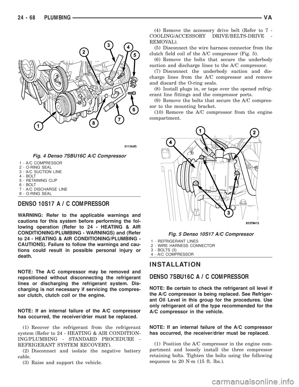
O-ring seals (Fig. 4).
(7) Install plugs in, or tape over the opened refrig-
erant line fittings and the compressor ports.
(8) Raise the vehicle on a hoist.
(9) If equipped with an add-on rear A/C system,
remove the lower A/C compressor and position it out
of the way (Refer to 24 - HEATING & AIR CONDI-
TIONING/PLUMBING/A/C COMPRESSOR -
REMOVAL - DENSO 10S17).
(10) Support the A/C compressor and remove the
compressor mounting bolts.
(11) Remove the A/C compressor from the engine
compartment.
VAPLUMBING 24 - 67
Page 2105 of 2305
DENSO 10S17A/CCOMPRESSOR
WARNING: Refer to the applicable warnings and
cautions for this system before performing the fol-
lowing operation (Refer to 24 - HEATING & AIR
CONDITIONING/PLUMBING - WARNINGS) and (Refer
to 24 - HEATING & AIR CONDITIONING/PLUMBING -
CAUTIONS). Failure to follow the warnings and cau-
tions could result in possible personal injury or
death.
NOTE: The A/C compressor may be removed and
repositioned without disconnecting the refrigerant
lines or discharging the refrigerant system. Dis-
charging is not necessary if servicing the compres-
sor clutch, clutch coil or the engine.
NOTE: If an internal failure of the A/C compressor
has occurred, the receiver/drier must be replaced.
(1) Recover the refrigerant from the refrigerant
system (Refer to 24 - HEATING & AIR CONDITION-
ING/PLUMBING - STANDARD PROCEDURE -
REFRIGERANT SYSTEM RECOVERY).
(2) Disconnect and isolate the negative battery
cable.
(3) Raise and support the vehicle.(4) Remove the accessory drive belt (Refer to 7 -
COOLING/ACCESSORY DRIVE/BELTS-DRIVE -
REMOVAL).
(5) Disconnect the wire harness connector from the
clutch field coil of the A/C compressor (Fig. 5).
(6) Remove the bolts that secure the underbody
suction and discharge lines to the A/C compressor.
(7) Disconnect the underbody suction and dis-
charge lines from the A/C compressor and remove
and discard the O-ring seals.
(8) Install plugs in, or tape over the opened refrig-
erant line fittings and the compressor ports.
(9) Remove the bolts that secure the A/C compres-
sor to the mounting bracket.
(10) Remove the A/C compressor from the engine
compartment.
INSTALLATION
DENSO 7SBU16CA/CCOMPRESSOR
NOTE: Be certain to check the refrigerant oil level if
the A/C compressor is being replaced. See Refriger-
ant Oil Level in this group for the procedures. Use
only refrigerant oil of the type recommended for the
A/C compressor in the vehicle.
NOTE: If an internal failure of the A/C compressor
has occurred, the receiver/drier must be replaced.
(1) Position the A/C compressor in the engine com-
partment and loosely install the three compressor
retaining bolts. Tighten the bolts using the following
sequence to 20 N´m (15 ft. lbs.).
Fig. 4 Denso 7SBU16C A/C Compressor
1 - A/C COMPRESSOR
2 - O-RING SEAL
3 - A/C SUCTION LINE
4 - BOLT
5 - RETAINING CLIP
6 - BOLT
7 - A/C DISCHARGE LINE
8 - O-RING SEAL
Fig. 5 Denso 10S17 A/C Compressor
1 - REFRIGERANT LINES
2 - WIRE HARNESS CONNECTOR
3 - BOLTS (3)
4 - A/C COMPRESSOR
24 - 68 PLUMBINGVA
Page 2106 of 2305
²The upper bolt at the front of the compressor.
²The lower bolt at the front of the compressor.
²The bolt at the rear of the compressor.
(2) If equipped with an add-on rear A/C system,
install the lower A/C compressor (Refer to 24 - HEAT-
ING & AIR CONDITIONING/PLUMBING/A/C COM-
PRESSOR - INSTALLATION - DENSO 10S17).
(3) Lower the vehicle.
(4) Remove the tape or plugs from the opened suc-
tion line fitting and the discharge line fitting and the
compressor ports.
(5) Lubricate new rubber O-ring seals with clean
refrigerant oil and install them onto the suction and
the discharge line fittings. Use only the specified
O-rings as they are made of a special material for the
R-134a system. Use only refrigerant oil of the type
recommended for the A/C compressor in the vehicle.
(6) Connect the A/C suction and discharge lines to
the A/C compressor.
(7) Install the bolts that secure the A/C suction
and discharge lines to the A/C compressor. Tighten
the bolts to 23 N´m (17 ft. lbs.).
(8) Connect the wire harness connector to the A/C
compressor clutch coil.
(9) Install the accessory drive belt (Refer to 7 -
COOLING/ACCESSORY DRIVE/DRIVE BELTS -
INSTALLATION).
(10) Replace the receiver/drier if the A/C compres-
sor is being replaced due to an internal failure (Refer
to 24 - HEATING & AIR CONDITIONING/PLUMB-
ING/RECEIVER/DRIER - REMOVAL) and (Refer to
24 - HEATING & AIR CONDITIONING/PLUMBING/
RECEIVER/DRIER - INSTALLATION).
(11) Reconnect the negative battery cable.
(12) Evacuate the refrigerant system (Refer to 24 -
HEATING & AIR CONDITIONING/PLUMBING -
STANDARD PROCEDURE - REFRIGERANT SYS-
TEM EVACUATE).
(13) Charge the refrigerant system (Refer to 24 -
HEATING & AIR CONDITIONING/PLUMBING -
STANDARD PROCEDURE - REFRIGERANT SYS-
TEM CHARGE).
DENSO 10S17A/CCOMPRESSOR
NOTE: Be certain to check the refrigerant oil level if
the A/C compressor is being replaced. See Refriger-
ant Oil Level in this group for the procedures. Use
only refrigerant oil of the type recommended for the
A/C compressor in the vehicle.
NOTE: If an internal failure of the A/C compressor
has occurred, the receiver/drier must be replaced.
(1) Position the A/C compressor in the engine com-
partment and loosely install the three compressorretaining bolts. Tighten the bolts using the following
sequence to 20 N´m (14 ft. lbs.).
²The upper bolt at the front of the compressor.
²The lower bolt at the front of the compressor.
²The bolt at the rear of the compressor.
(2) Remove the tape or plugs from the opened
underbody suction and discharge line fittings and
compressor ports.
(3) Lubricate new rubber O-ring seals with clean
refrigerant oil and install them onto the suction and
the discharge line fittings. Use only the specified
O-rings as they are made of a special material for the
R-134a system. Use only refrigerant oil of the type
recommended for the A/C compressor in the vehicle.
(4) Connect the underbody suction and discharge
lines to the A/C compressor.
(5) Install the bolts that secure the underbody suc-
tion and discharge lines to the A/C compressor.
Tighten the bolts to 21 N´m (15 ft. lbs.).
(6) Connect the wire harness connector to the A/C
compressor clutch coil.
(7) Install the accessory drive belt (Refer to 7 -
COOLING/ACCESSORY DRIVE/BELTS-DRIVE -
INSTALLATION).
(8) Lower the vehicle.
(9) Replace the receiver/drier if the A/C compressor
is being replaced due to an internal failure (Refer to
24 - HEATING & AIR CONDITIONING/PLUMBING/
RECEIVER/DRIER - REMOVAL) and (Refer to 24 -
HEATING & AIR CONDITIONING/PLUMBING/RE-
CEIVER/DRIER - INSTALLATION).
(10) Reconnect the negative battery cable.
(11) Evacuate the refrigerant system (Refer to 24 -
HEATING & AIR CONDITIONING/PLUMBING -
STANDARD PROCEDURE - REFRIGERANT SYS-
TEM EVACUATE).
(12) Charge the refrigerant system (Refer to 24 -
HEATING & AIR CONDITIONING/PLUMBING -
STANDARD PROCEDURE - REFRIGERANT SYS-
TEM CHARGE).
A / C CONDENSER
DESCRIPTION
The condenser is located in the air flow in front of
the engine cooling radiator. The condenser is a heat
exchanger that allows the high-pressure refrigerant
gas being discharged by the compressor to give up its
heat to the air passing over the condenser fins.
OPERATION
When the refrigerant gas gives up its heat, it con-
denses. When the refrigerant leaves the condenser, it
has become a high-pressure liquid refrigerant. The
volume of air flowing over the condenser fins is crit-
ical to the proper cooling performance of the air con-
ditioning system. Therefore, it is important that
VAPLUMBING 24 - 69
Page 2158 of 2305
INDEX
ABS INDICATOR.......................8J-9ACCELERATOR PEDAL POSITION SENSOR. . . 14-32
ACCESSORY SWITCH BEZEL............23-56
ADR INDICATOR.....................8J-10
AIR CLEANER ELEMENT................9-21
AIR CLEANER HOUSING................9-21
AIR FILTER ....................24-45, 24-58
AIR OUTLET TEMPERATURE SENSOR....24-16
AIR OUTLETS.......................24-45
AIRBAG CONTROL MODULE.............8O-8
AIRBAG INDICATOR...................8J-11
ALB CONTROLLER....................5-16
ALB LEVER..........................5-16
AMBIENT TEMPERATURE INDICATOR.....8J-11
AMBIENT TEMPERATURE SENSOR.......24-17
ANTENNA BODY & CABLE..............8A-1
ARMREST..........................23-79
ASH RECEIVER......................23-57
ASH RECEIVER / CIGAR LIGHTER LAMP
UNIT..............................8L-30
ASSIST HANDLE.....................23-71
AUDIO..............................8A-1
AUTOMATIC TRANSMISSION NAG1 -
SERVICE INFORMATION................21-3
A - PILLAR TRIM.....................23-70
A / C CLUTCH RELAY.................24-24
A / C COMPRESSOR CLUTCH COIL.......24-12
A / C COMPRESSOR CLUTCH............24-8
A / C COMPRESSOR..................24-66
A / C CONDENSER COVER.............24-52
A / C CONDENSER FAN RELAY..........24-26
A / C CONDENSER HOUSING...........24-52
A / C CONDENSER....................24-69
A / C CONTROL MODULE..............24-28
A / C DISCHARGE LINE................24-71
A / C EVAPORATOR COVER.............24-55
A / C EVAPORATOR HOUSING...........24-55
A / C EVAPORATOR...................24-72
A / C EXPANSION VALVE...............24-73
A / C HEATER CONTROL...............24-12
A / C HIGH PRESSURE SWITCH.........24-30
A / C LOW PRESSURE SWITCH.........24-32
A / C PRESSURE TRANSDUCER.........24-14
BACKLITE - BULKHEAD TRIM PANEL.....23-84
BACKUP LAMP BULB..................8L-5
BASECOAT / CLEARCOAT FINISH........23-77
BATTERY CABLES....................8F-14
BATTERY HOLDDOWN.................8F-13
BATTERY SYSTEM.....................8F-1
BATTERY TRAY......................8F-16
BATTERY............................8F-6
BEARINGS - DIFFERENTIAL CASE.........3-38
BEARING / SEAL - AXLE HUB............3-28
BEARING / SEAL - AXLE................3-24
BELT TENSIONERS.....................7-5
BLOWER MOTOR RELAY...............24-33
BLOWER MOTOR RESISTOR............24-17
BLOWER MOTOR SWITCH........24-19, 24-35
BLOWER MOTOR...............24-47, 24-58
BODY...............................23-1
BOOST PRESSURE SENSOR............14-33
BRAKE INDICATOR...................8J-12
BRAKE LAMP SWITCH.................8L-6
BRAKE LINES.........................5-8
BRAKE PADS / SHOES...................5-8
BRAKE WEAR INDICATOR..............8J-13
BRAKES - ABS........................5-30
BRAKES - BASE........................5-2
BRAKE / PARK LAMP BULB.............8L-7
BULKHEAD TRIM PANEL...............23-72
BUMPERS...........................13-1
BUSHINGS............................2-3
B - PILLAR TRIM.....................23-71
CABIN HEATER.....................24-104
CABLE TENSIONER....................5-24
CABLE..............................8P-2
CABLES.............................5-24
CAMSHAFT POSITION SENSOR..........14-33
CAMSHAFT(S)........................9-28
CARGO LAMP SWITCH................8L-31
CARGO / DOME LAMP BULB............8L-30
CARGO / DOME LAMP UNIT............8L-31
CARPETS AND FLOOR MATS...........23-72
CATALYTIC CONVERTER
................11-3
CENTER BEARING
......................3-9
CENTER HIGH MOUNTED STOP LAMP BULB. . . 8L-8CENTER HIGH MOUNTED STOP LAMP UN.....8L-8
CENTER ROLLER ARM
................23-36CENTER TRACK......................23-37
CENTRAL TIMER MODULE..............8E-1
CHARGE AIR COOLER AND PLUMBING....11-4
CHARGING INDICATOR................8J-14
CHARGING SYSTEM..................8F-17
CHECK VALVE.......................8R-11
CHECK.......................23-13, 23-23
CHIME / BUZZER......................8B-1
CIGAR LIGHTER OUTLET............8W-97-1
CIRCUIT BREAKER.................8W-97-2
CLEARANCE LAMP BULB...............8L-9
CLEARANCE LAMP UNIT................8L-9
CLOCK.............................8J-14
CLOCKSPRING......................8O-12
CLUSTER BEZEL.....................23-55
COLUMN............................19-4
CONNECTOR.......................Intro.-9
CONNECTOR/GROUND/SPLICE
LOCATION........................8W-91-1
CONTROLLER ANTILOCK BRAKE.........8E-3
COOLANT LEVEL SENSOR...............7-13
COOLANT LOW INDICATOR.............8J-15
COOLANT............................7-9
COOLING.............................7-1
COWL TRIM........................23-73
CRANKCASE VENTILATION BREATHER......25-2
CRANKCASE VENTILATION HEATER.......25-1
CRANKSHAFT OIL SEAL - FRONT.........9-42
CRANKSHAFT OIL SEAL - REAR..........9-41
CRANKSHAFT POSITION SENSOR........14-35
CRANKSHAFT........................9-39
CUP HOLDER........................23-57
CYLINDER HEAD COVER(S).............9-33
CYLINDER HEAD......................9-22
DAYTIME RUNNING LAMP RELAY.......8L-10
DEFROSTER DUCTS..................24-47
DIFFERENTIAL........................3-31
DIODE............................Intro.-9
DISC BRAKE CALIPER ADAPTER.........5-14
DISC BRAKE CALIPERS.................5-11
DOME LAMP / INTRUSION SENSOR
BULB..............................8L-33
DOME LAMP / INTRUSION SENSOR......8L-33
DOME / READING LAMP BULB..........8L-32
DOME / READING LAMP UNIT..........8L-32
DOOR GLASS............23-15, 23-30, 23-46
DOOR JAMB SWITCH.................8L-34
DOOR LOCK MOTOR...................8N-1
DOOR OPENING SEALS................23-90
DOOR........................23-14, 23-23
DRIVE BELTS..........................7-5
DRIVER AIRBAG.....................8O-16
DRIVER HEATED SEAT SWITCH.........8G-11
D - PILLAR TRIM.....................23-73
ELECTRIC COOLANT PUMP.............24-75
ELECTRICAL.........................5-30
ELECTROHYDRAULIC UNIT............21-105
ENGINE BLOCK HEATER................7-14
ENGINE BLOCK.......................9-37
ENGINE CONTROL MODULE.............8E-3
ENGINE COOLANT TEMP SENSOR........7-15
ENGINE COOLANT THERMOSTAT.........7-16
ENGINE CRADLE CROSSMEMBER........13-8
ENGINE TEMPERATURE GAUGE.........8J-15
ENGINE..............................9-2
ENTRY / EXIT LAMP BULB.............8L-34
ENTRY / EXIT LAMP UNIT..............8L-35
ESP INDICATOR......................8J-16
EVAPORATOR TEMPERATURE
SENSOR......................24-19, 24-37
EXHAUST GAS RECIRCULATION..........25-4
EXHAUST MANIFOLD..................9-68
EXHAUST PIPE.......................11-3
EXHAUST SYSTEM....................11-1
EXHAUST TUBE.....................24-105
EXTERIOR HANDLE.......23-16, 23-31, 23-35
FAN DRIVE VISCOUS CLUTCH...........7-17
FASTENER IDENTIFICATION...........Intro.-3
FASTENER USAGE...................Intro.-6
FINESSE SANDING / BUFFING & POLISH . . 23-78
FLOOR DISTRIBUTION DUCTS..........24-47
FLUID AND FILTER..................21-131
FLUID CAPACITIES.....................0-5
FLUID COOLER TUBE
.................19-13
FLUID FILL / CHECK LOCATIONS
..........0-5
FLUID RESERVOIR
....................5-15
FLUID TYPES
..........................0-1
FLYWHEEL
...........................9-43FOG LAMP BULB.....................8L-10
FOG LAMP RELAY....................8L-11
FOG LAMP SWITCH...................8L-12
FRAME..............................13-3
FREEWHEELING CLUTCH.............21-135
FRONT BUMPER - STEPS...............13-2
FRONT DOOR INNER BELT
WEATHERSTRIP.....................23-90
FRONT DOOR OUTER BELT
WEATHERSTRIP.....................23-90
FRONT FASCIA.......................13-2
FRONT LAMP UNIT...................8L-13
FRONT POSITION LAMP BULB..........8L-14
FRONT SEAT BELT & RETRACTOR.......8O-20
FRONT SEAT BELT BUCKLE............8O-23
FRONT TURN / PARK / SIDE MARKER
LAMP BULB.........................8L-15
FRONT WHEEL SPEED SENSOR..........5-31
FRONT...............................2-1
FUEL DELIVERY.......................14-6
FUEL DOSING PUMP.................24-106
FUEL DRAIN TUBES..................14-10
FUEL FILL DOOR.....................23-48
FUEL FILTER CLOGGED INDICATOR......8J-17
FUEL FILTER........................14-10
FUEL GAUGE........................8J-17
FUEL INJECTOR.......................14-35
FUEL LEVEL SENDING UNIT / SENSOR....14-28
FUEL LINE.........................24-107
FUEL LINES.........................14-11
FUEL PRESSURE SENSOR.............14-39
FUEL PRESSURE SOLENOID............14-40
FUEL PUMP MODULE.................14-18
FUEL PUMP.........................14-13
FUEL QUANTITY CONTROL VALVE.......14-21
FUEL RAIL PRESSURE SENSOR.........14-12
FUEL RAIL..........................14-22
FUEL SYSTEM........................14-1
FUEL TANK.........................14-23
FUEL TEMPERATURE SENSOR..........14-42
FUSE BLOCK #1...................8W-97-2
FUSE BLOCK #2...................8W-97-3
GAP AND FLUSH.....................23-91
GEAR SELECTOR INDICATOR...........8J-18
GEAR...............................19-7
GEARSHIFT CABLE..................21-138
GEAR - PINION / RING.................3-41
GENERATOR DECOUPLER PULLEY.......8F-19
GENERATOR........................8F-18
GLOVE BOX.........................23-58
GLOW PLUG RELAY....................8I-1
GLOW PLUG..........................8I-1
GRILLE............................23-48
HCU (HYDRAULIC CONTROL UNIT).......5-36
HEADLAMP LEVELING MOTOR..........8L-16
HEADLAMP LEVELING SWITCH.........8L-17
HEADLINER.........................23-73
HEADREST..........................23-79
HEATED GLASS.......................8G-1
HEATED MIRRORS....................8G-9
HEATED SEAT ELEMENT...............8G-12
HEATED SEAT RELAY.................8G-12
HEATED SEAT SENSOR................8G-13
HEATED SEATS ......................8G-10
HEATER CORE.......................24-76
HEATER UNIT......................24-110
HEATING & AIR CONDITIONING..........24-1
HIGH BEAM HEADLAMP BULB..........8L-18
HIGH BEAM INDICATOR...............8J-19
HINGE..................23-17, 23-32, 23-51
HOISTING............................0-5
HOLDING CLUTCH B1................21-143
HOLDING CLUTCH B2................21-148
HOLDING CLUTCHES.................21-141
HOOD.............................23-51
HORN SWITCH.......................8H-1
HORN..............................8H-1
HOSES.............................19-14
HUB / BEARING........................2-4
HVAC HOUSING......................24-48
HYDRAULIC / MECHANICAL..............5-5
IGNITION CONTROL....................8I-1
INLET HOSE........................24-111
INPUT CLUTCH K1
...................21-92
INPUT CLUTCH K2
...................21-97
INPUT CLUTCH K3
..................21-102
INPUT CLUTCHES
....................21-90
INPUT SPEED SENSORS
..............21-153
VAINDEX 1
Description Group-Page Description Group-Page Description Group-Page