2006 MERCEDES-BENZ SPRINTER drive belt
[x] Cancel search: drive beltPage 858 of 2305

INSTALLATION
(1) Position the central timer module in the vehicle
(2) Connect the wire harness connectors to the
central timer module.
(3) Install the screws that secure the central timer
module. Tighten the screws securely.
(4) Route the seat belt latch wire lead through the
hole in the closeout panel and position the panel
beneath the driver seat cushion
(5) Install the screws that secure the closeout
panel beneath the driver seat cushion. Tighten the
screws securely.
(6) Connect the wire harness connector to the seat
belt latch connector.
(7) Slide the driver seat to back to its original posi-
tion.
(8) Reconnect the negative battery cable.
CONTROLLER ANTILOCK
BRAKE
DESCRIPTION
The Controler Antilock Brake (CAB) is mounted to
the Hydraulic Control Unit (HCU) and operates the
ABS system.
REMOVAL
(1) Remove the negative battery cable from the
battery.
(2) Pull up on the CAB harness connector release
and remove connector.
(3) Remove the CAB mounting bolts.
(4) Remove the CAB from the HCU.
INSTALLATION
(1) Install CAB to the HCU.
(2) Install mounting bolts. Tighten to 2 N´m (16 in.
lbs.).
(3) Install the wiring harness connector to the
CAB and push down on the release to secure the con-
nector.
(4) Install negative battery cable to the battery.
ENGINE CONTROL MODULE
DESCRIPTION
The electronic control module (ECM) is mounted to
the left lower dash panel and consists of an electronic
printed circuit board which is designed as a milliliter
board assembly fitted on both sides. The routing of
the wiring harness connector at the ECM connector
are split into interfering cables and sensitive cables
in order to achieve improved electromagnetic compat-
ibility. The smaller wiring harness connector is used
for the vehicle wiring harness and the larger harness
is used for the engine wiring harness. The ECM
stores engine specific data, monitors the connected
sensor and analyzes their measurement (Fig. 2).
Its task consists in controlling the following sys-
tems in line with the analysis of the input signals:
²Fuel Supply System
²Injected Quantity Control
²Emission Control System
²Charge Pressure Control
²Cruise Control
²A/C Compressor Shut-Off
²Pre-Heating Output Relay for the Glow Plugs
²Vehicle Theft
²Air Bag
²Monitors inputs/outputs, checks plausibility and
stores faults
²Share information with other control modules
²Diagnosis
If a sensor should fail, provided the fault is not
serious, the ECM will continue to operate the engine
in Limp-Home Mode (emergency mode) using a
default value for the missing signal. The ECM
ensures that, continuing to operate the engine will
not cause damage or effect safety, otherwise a Engine
shut-off process will be carried out (Fig. 3).Fig. 1 Central Timer Module
1 - DRIVER SEAT
2 - WIRE HARNESS CONNECTOR
3 - SCREW (2)
4 - CLOSEOUT PANEL
5 - CENTRAL TIMER MODULE
6 - WIRE HARNESS CONNECTOR (2)
7 - SCREW (2)
VAELECTRONIC CONTROL MODULES 8E - 3
Page 883 of 2305
SPECIAL TOOLS
GENERATOR
DESCRIPTION
The generator is belt-driven by the engine using a
serpentine-type drive belt. It is serviced only as a
complete assembly. If the generator fails for any rea-
son, the entire assembly must be replaced.
On certain engines, the decoupler pulley may be
replaced separately.
OPERATION
As the energized rotor begins to rotate within the
generator, the spinning magnetic field induces a cur-
rent into the windings of the stator coil. Once the
generator begins producing sufficient current, it also
provides the current needed to energize the rotor.
The stator winding connections deliver the induced
AC current to 3 positive and 3 negative diodes for
rectification. From the diodes, rectified DC current isdelivered to the vehicle electrical system through the
generator battery terminal.
Although the generators appear the same exter-
nally, different generators with different output rat-
ings are used on this vehicle. Be certain that the
replacement generator has the same output rating
and part number as the original unit. Refer to Spec-
ifications and see Generator Ratings for amperage
ratings and part numbers.
Noise emitting from the generator may be caused
by: worn, loose or defective bearings; a loose or defec-
tive drive pulley (decoupler pulley); incorrect, worn,
damaged or misadjusted fan drive belt; loose mount-
ing bolts; a misaligned drive pulley or a defective sta-
tor or diode.
An instrument panel mounted, battery charge indi-
cator lamp is used. When the key is in the on posi-
tion, the lamp will be illuminated. This is done as a
bulb check. If this lamp remains illuminated while
the engine is running, a Diagnostic Trouble Code
(DTC) has been detected for the charging system.
REMOVAL
CAUTION: DISCONNECT NEGATIVE CABLE FROM
BATTERY BEFORE REMOVING BATTERY OUTPUT
WIRE FROM GENERATOR. FAILURE TO DO SO
CAN RESULT IN INJURY.
CAUTION: Never force a belt over a pulley rim
using a screwdriver. The synthetic fiber of the belt
can be damaged.
CAUTION: When installing a serpentine accessory
drive belt, the belt MUST be routed correctly. The
water pump will be rotating in the wrong direction if
the belt is installed incorrectly, causing the engine
to overheat. Refer to belt routing label in engine
compartment, or refer to Belt Schematics in Cooling
System.
(1) Disconnect and isolate negative battery cable.
(2) Remove generator drive belt. Refer to Cooling
System for procedure.
(3) Raise and support vehicle.
(4) Remove protective plastic cover from B+ stud
at top of generator.
(5) Remove nut securing battery output cable to
B+ terminal at top of generator.
(6) Unplug field terminal connector at rear of gen-
erator.
(7) Remove 4 generator mounting bolts (Torx-style
#12 bit) (Fig. 1).
(8) Remove generator from lower side of vehicle.
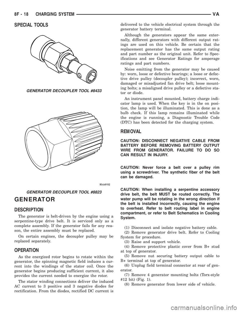
GENERATOR DECOUPLER TOOL #8433
GENERATOR DECOUPLER TOOL #8823
8F - 18 CHARGING SYSTEMVA
Page 884 of 2305
INSTALLATION
(1) Raise and support vehicle.
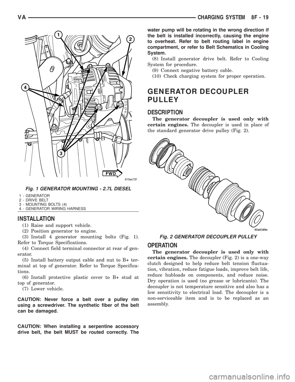
(2) Position generator to engine.
(3) Install 4 generator mounting bolts (Fig. 1).
Refer to Torque Specifications.
(4) Connect field terminal connector at rear of gen-
erator.
(5) Install battery output cable and nut to B+ ter-
minal at top of generator. Refer to Torque Specifica-
tions.
(6) Install protective plastic cover to B+ stud at
top of generator.
(7) Lower vehicle.
CAUTION: Never force a belt over a pulley rim
using a screwdriver. The synthetic fiber of the belt
can be damaged.
CAUTION: When installing a serpentine accessory
drive belt, the belt MUST be routed correctly. Thewater pump will be rotating in the wrong direction if
the belt is installed incorrectly, causing the engine
to overheat. Refer to belt routing label in engine
compartment, or refer to Belt Schematics in Cooling
System.
(8) Install generator drive belt. Refer to Cooling
System for procedure.
(9) Connect negative battery cable.
(10) Check charging system for proper operation.
GENERATOR DECOUPLER
PULLEY
DESCRIPTION
The generator decoupler is used only with
certain engines.The decoupler is used in place of
the standard generator drive pulley (Fig. 2).
OPERATION
The generator decoupler is used only with
certain engines.The decoupler (Fig. 2) is a one-way
clutch designed to help reduce belt tension fluctua-
tion, vibration, reduce fatigue loads, improve belt life,
reduce hubloads on components, and reduce noise.
Dry operation is used (no grease or lubricants). The
decoupler is not temperature sensitive and also has a
low sensitivity to electrical load. The decoupler is a
non-serviceable item and is to be replaced as an
assembly.
Fig. 1 GENERATOR MOUNTING - 2.7L DIESEL
1 - GENERATOR
2 - DRIVE BELT
3 - MOUNTING BOLTS (4)
4 - GENERATOR WIRING HARNESS
Fig. 2 GENERATOR DECOUPLER PULLEY
VACHARGING SYSTEM 8F - 19
Page 885 of 2305
DIAGNOSIS AND TESTING - GENERATOR DECOUPLER
CONDITION POSSIBLE CAUSES CORRECTION
Does not drive generator
(generator not charging)Internal failure Replace decoupler
Noise coming from decou-
plerInternal failure Replace decoupler
REMOVAL
The generator decoupler is used only with
certain engines.
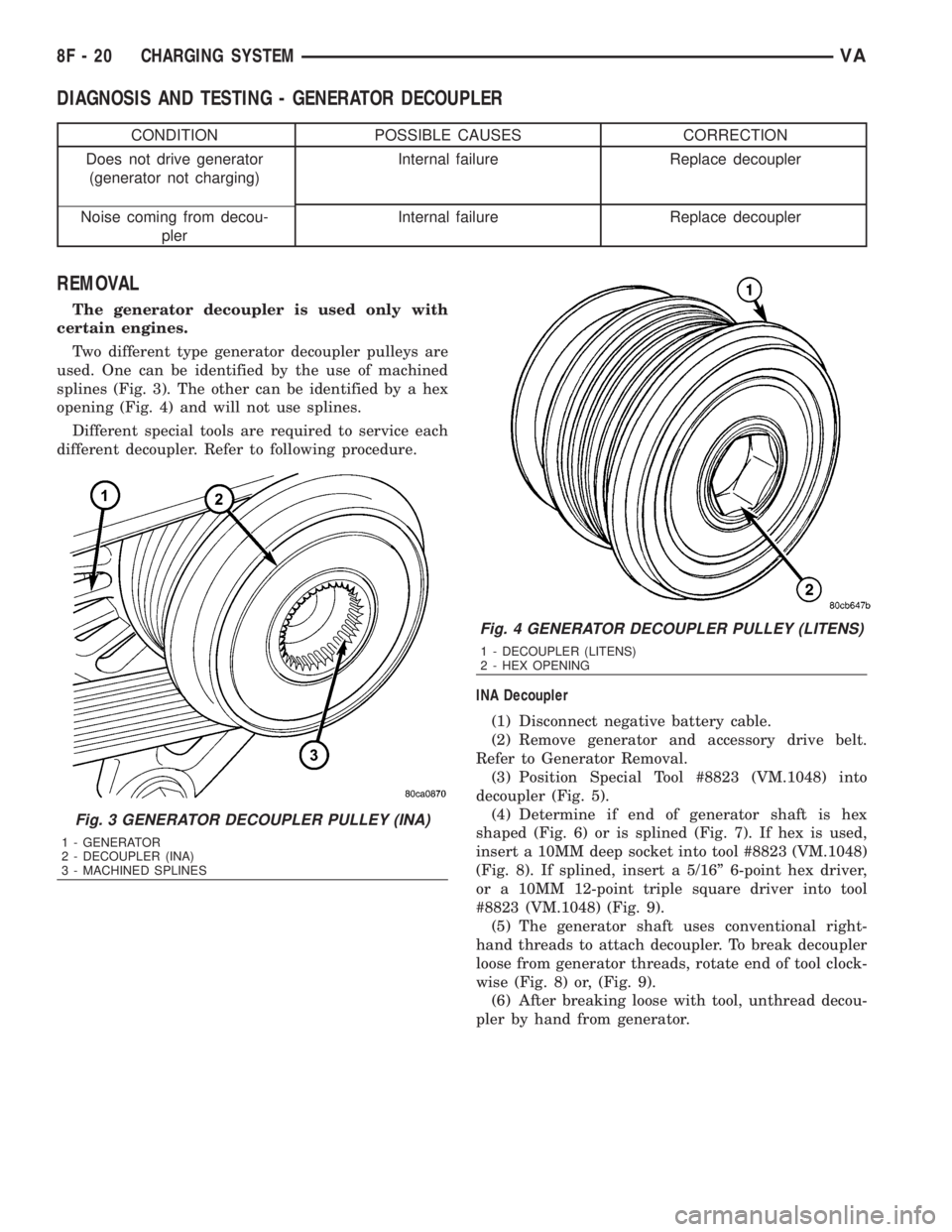
Two different type generator decoupler pulleys are
used. One can be identified by the use of machined
splines (Fig. 3). The other can be identified by a hex
opening (Fig. 4) and will not use splines.
Different special tools are required to service each
different decoupler. Refer to following procedure.
INA Decoupler
(1) Disconnect negative battery cable.
(2) Remove generator and accessory drive belt.
Refer to Generator Removal.
(3) Position Special Tool #8823 (VM.1048) into
decoupler (Fig. 5).
(4) Determine if end of generator shaft is hex
shaped (Fig. 6) or is splined (Fig. 7). If hex is used,
insert a 10MM deep socket into tool #8823 (VM.1048)
(Fig. 8). If splined, insert a 5/16º 6-point hex driver,
or a 10MM 12-point triple square driver into tool
#8823 (VM.1048) (Fig. 9).
(5) The generator shaft uses conventional right-
hand threads to attach decoupler. To break decoupler
loose from generator threads, rotate end of tool clock-
wise (Fig. 8) or, (Fig. 9).
(6) After breaking loose with tool, unthread decou-
pler by hand from generator.
Fig. 3 GENERATOR DECOUPLER PULLEY (INA)
1 - GENERATOR
2 - DECOUPLER (INA)
3 - MACHINED SPLINES
Fig. 4 GENERATOR DECOUPLER PULLEY (LITENS)
1 - DECOUPLER (LITENS)
2 - HEX OPENING
8F - 20 CHARGING SYSTEMVA
Page 887 of 2305
Litens Decoupler
(1) Disconnect negative battery cable.
(2) Remove generator and accessory drive belt.
Refer to Generator Removal.
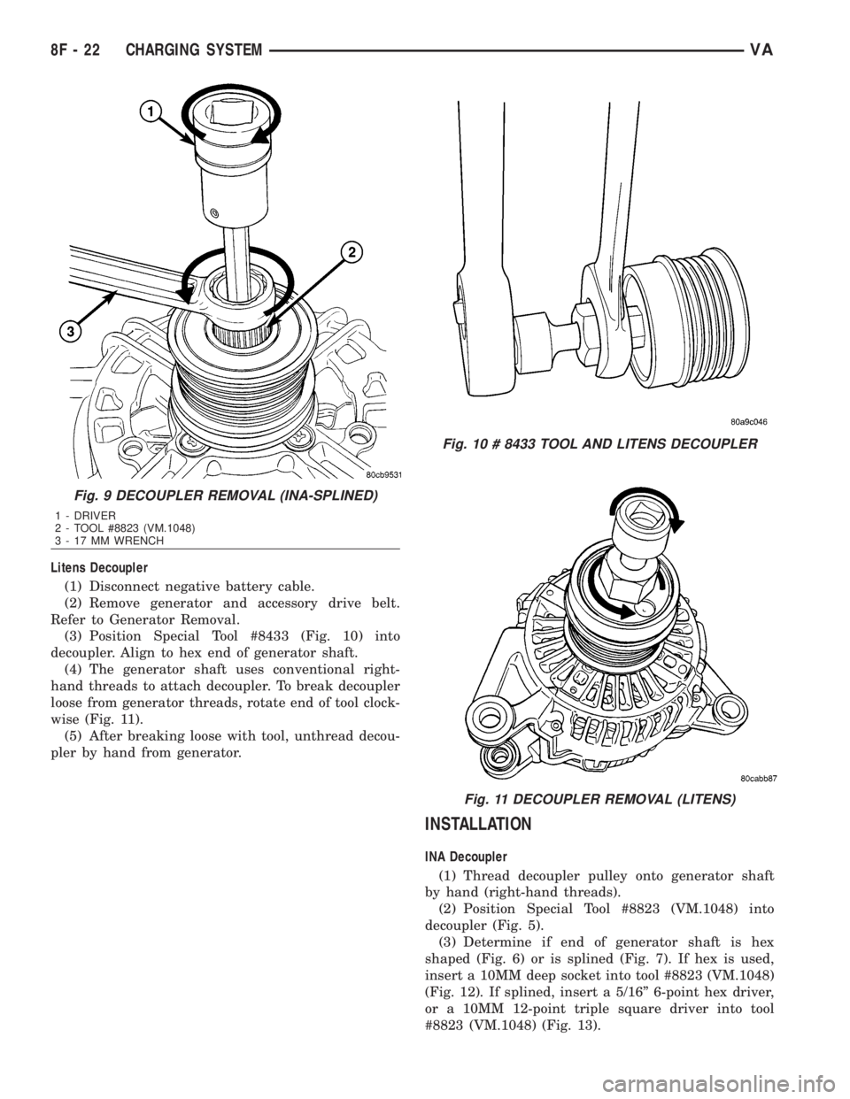
(3) Position Special Tool #8433 (Fig. 10) into
decoupler. Align to hex end of generator shaft.
(4) The generator shaft uses conventional right-
hand threads to attach decoupler. To break decoupler
loose from generator threads, rotate end of tool clock-
wise (Fig. 11).
(5) After breaking loose with tool, unthread decou-
pler by hand from generator.
INSTALLATION
INA Decoupler
(1) Thread decoupler pulley onto generator shaft
by hand (right-hand threads).
(2) Position Special Tool #8823 (VM.1048) into
decoupler (Fig. 5).
(3) Determine if end of generator shaft is hex
shaped (Fig. 6) or is splined (Fig. 7). If hex is used,
insert a 10MM deep socket into tool #8823 (VM.1048)
(Fig. 12). If splined, insert a 5/16º 6-point hex driver,
or a 10MM 12-point triple square driver into tool
#8823 (VM.1048) (Fig. 13).
Fig. 9 DECOUPLER REMOVAL (INA-SPLINED)
1 - DRIVER
2 - TOOL #8823 (VM.1048)
3 - 17 MM WRENCH
Fig. 10 # 8433 TOOL AND LITENS DECOUPLER
Fig. 11 DECOUPLER REMOVAL (LITENS)
8F - 22 CHARGING SYSTEMVA
Page 888 of 2305
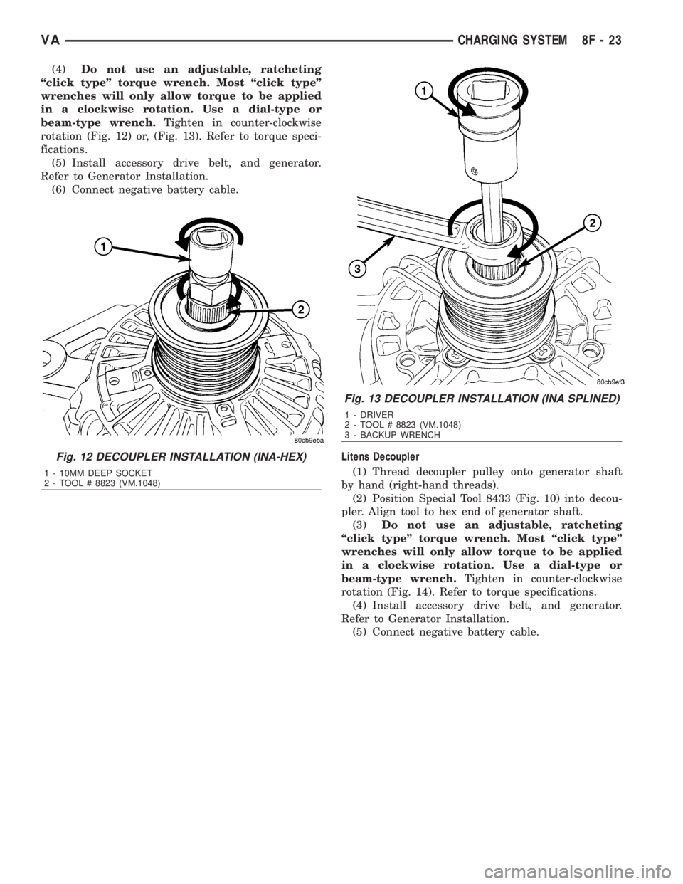
(4)Do not use an adjustable, ratcheting
ªclick typeº torque wrench. Most ªclick typeº
wrenches will only allow torque to be applied
in a clockwise rotation. Use a dial-type or
beam-type wrench.Tighten in counter-clockwise
rotation (Fig. 12) or, (Fig. 13). Refer to torque speci-
fications.
(5) Install accessory drive belt, and generator.
Refer to Generator Installation.
(6) Connect negative battery cable.
Litens Decoupler
(1) Thread decoupler pulley onto generator shaft
by hand (right-hand threads).
(2) Position Special Tool 8433 (Fig. 10) into decou-
pler. Align tool to hex end of generator shaft.
(3)Do not use an adjustable, ratcheting
ªclick typeº torque wrench. Most ªclick typeº
wrenches will only allow torque to be applied
in a clockwise rotation. Use a dial-type or
beam-type wrench.Tighten in counter-clockwise
rotation (Fig. 14). Refer to torque specifications.
(4) Install accessory drive belt, and generator.
Refer to Generator Installation.
(5) Connect negative battery cable.
Fig. 12 DECOUPLER INSTALLATION (INA-HEX)
1 - 10MM DEEP SOCKET
2 - TOOL # 8823 (VM.1048)
Fig. 13 DECOUPLER INSTALLATION (INA SPLINED)
1 - DRIVER
2 - TOOL # 8823 (VM.1048)
3 - BACKUP WRENCH
VACHARGING SYSTEM 8F - 23
Page 907 of 2305
DEFOGGER SWITCH CONNECTOR PIN
CALL-OUT
PIN FUNCTION
1 FUSED B+ (DRL RELAY)
3 IGNITION SWITCH OUTPUT (START-
RUN)
5 PANEL LAMPS DRIVER
7 DEFOGGER SWITCH OUTPUT
9 PANEL LAMPS DRIVER
10 GROUND
REMOVAL
WARNING: To avoid personal injury or death, on
vehicles equipped with airbags, disable the supple-
mental restraint system before attempting any
steering wheel, steering column, airbag, seat belt
tensioner, or instrument panel component diagno-
sis or service. Disconnect and isolate the battery
negative (ground) cable, then wait two minutes for
the system capacitor to discharge before perform-
ing further diagnosis or service. This is the only
sure way to disable the supplemental restraint sys-
tem. Failure to take the proper precautions could
result in accidental airbag deployment.
(1) Disconnect and isolate the negative battery
cable.
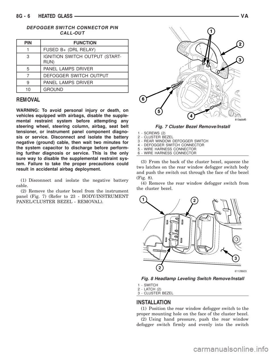
(2) Remove the cluster bezel from the instrument
panel (Fig. 7) (Refer to 23 - BODY/INSTRUMENT
PANEL/CLUSTER BEZEL - REMOVAL).(3) From the back of the cluster bezel, squeeze the
two latches on the rear window defogger switch body
and push the switch out through the face of the bezel
(Fig. 8).
(4) Remove the rear window defogger switch from
the cluster bezel.
INSTALLATION
(1) Position the rear window defogger switch to the
proper mounting hole on the face of the cluster bezel.
(2) Using hand pressure, push the rear window
defogger switch firmly and evenly into the switch
Fig. 7 Cluster Bezel Remove/Install
1 - SCREWS (2)
2 - CLUSTER BEZEL
3 - REAR WINDOW DEFOGGER SWITCH
4 - DEFOGGER SWITCH CONNECTOR
5 - WIRE HARNESS CONNECTOR
6 - WIRE HARNESS CONNECTOR
Fig. 8 Headlamp Leveling Switch Remove/Install
1 - SWITCH
2 - LATCH (2)
3 - CLUSTER BEZEL
8G - 6 HEATED GLASSVA
Page 925 of 2305

INDICATORS
Indicators are located in various positions within
the EMIC and are all connected to the EMIC elec-
tronic circuit board. The ambient temperature indica-
tor (optional), brake indicator, brake wear indicator,
charging indicator, coolant low indicator, high beam
indicator, low fuel indicator, park brake indicator,
seatbelt indicator, turn signal indicators, and washer
fluid indicator operate based upon hard wired inputs
to the EMIC. The airbag (SRS) indicator is normally
controlled by a hard wired input from the Airbag
Control Module (ACM); however, if the EMIC sees an
abnormal or no input from the ACM, it will automat-
ically turn the airbag indicator On until the hard
wired input from the ACM has been restored. The
Malfunction Indicator Lamp (MIL) is normally con-
trolled by CAN data bus messages from the Engine
Control Module (ECM); however, if the EMIC loses
CAN data bus communication, the EMIC circuitry
will automatically turn the MIL on until CAN data
bus communication is restored. The EMIC uses CAN
data bus messages from the ECM, the ACM, and the
Controller Antilock Brake to control all of the
remaining indicators.
The various EMIC indicators are controlled by dif-
ferent strategies; some receive battery feed from the
EMIC circuitry and have a switched ground, while
others are grounded through the EMIC circuitry and
have a switched battery feed. However, all indicators
are completely controlled by the EMIC microproces-
sor based upon various hard wired and electronic
message inputs. Except for the indications provided
by the multi-function indicator Liquid Crystal Dis-
play (LCD) unit, all indicators are illuminated at a
fixed intensity, which is not affected by the selected
illumination intensity of the EMIC general illumina-
tion lamps.
The hard wired indicator inputs may be diagnosed
using conventional diagnostic methods. However,
proper testing of the EMIC circuitry and the CAN
bus message controlled indicators requires the use of
a diagnostic scan tool. Refer to the appropriate diag-
nostic information. Specific details of the operation
for each indicator may be found elsewhere in this
service information.
CLUSTER ILLUMINATION
The EMIC has several general illumination lamps
that are illuminated when the exterior lighting is
turned on with the multi-function switch. The illumi-
nation intensity of these lamps is adjusted by a dim-
ming level input received from the multi-function
indicator ª+º (plus) and ª±º (minus) switch push but-
tons that extend through the lower edge of the clus-
ter lens below the right end of the multi-function
indicator. When the exterior lighting is turned Off,
the display is illuminated at maximum brightness.
When the exterior lighting is turned On and thetransmission gear selector is in the Park position,
depressing the plus switch push button brightens the
display lighting, and depressing the minus switch
push button dims the display lighting. The EMIC
also provides a Pulse-Width Modulated (PWM) panel
lamps dimmer output that can be used to synchro-
nize the illumination lighting levels of external illu-
mination lamps (up to about 23 to 30 watts) with
that of the EMIC.
The hard wired multi-function switch input and
the EMIC panel lamps dimmer output may be diag-
nosed using conventional diagnostic methods. How-
ever, proper testing of the PWM control of the EMIC
and the electronic dimming level inputs from the
multi-function indicator push buttons requires the
use of a diagnostic scan tool. Refer to the appropriate
diagnostic information.
INPUT AND OUTPUT CIRCUITS
HARD WIRED INPUTS
The hard wired inputs to the EMIC include the fol-
lowing:
NOTE: Final approved circuit names were not yet
available at the time this information was compiled.
²Airbag Indicator Driver
²Ambient Temperature Sensor Signal
(Optional)
²Brake Wear Indicator Sense
²Charging Indicator Driver
²Coolant Level Switch Sense
²Front Door Jamb Switch Sense
²Fuel Level Sensor Signal
²Fused B(+)
²Fused Ignition Switch Output
²High Beam Indicator Driver
²Key-In Ignition Switch Sense
²Left Turn Signal
²Park Brake Switch Sense
²Right Turn Signal
²Seat Belt Switch Sense
²Washer Fluid Switch Sense (Optional)
Refer to the appropriate wiring information for
additional details.
HARD WIRED OUTPUTS
The hard wired outputs of the EMIC include the
following:
²Engine Running Relay Control
²Panel Lamps Driver
Refer to the appropriate wiring information for
additional details.
8J - 6 INSTRUMENT CLUSTERVA